


 Loading...
MICROWAVE HOOD COMBINATION
BUMP OUT KIT
INSTALLATION INSTRUCTIONS
If cabinets are deeper than 14"(35.6 cm) but no more than 15"(38.1 cm), use the bump out mounting kit to replace the mounting bracket that comes with your unit.
These installation instructions are only for the Bump out mounting kit, for full microwave hood combination installation, please refer to the installation instructions that came with the microwave hood combination.
This installation instruction is suitable for two product height dimensions. Before installation, please measure your product height and choose section I or section II for installation. If your product height is around 171/8" (43.5 cm), please see Section I. If your product
height is around 105/16" (26.2 cm), please see Section II.
Section I |
|
Section II |
|
|
|
/8 |
|
171 |
" |
(43.5 cm) |
|
|
/ |
16 |
10 |
5 |
" |
(26.2 |
cm) |
|
See section I installation in the following pages.
See section II installation in the following pages.
Table of Contents |
|
MICROWAVE HOOD COMBINATION SAFETY.............................................. |
2 |
SECTION I & II................................................................................................... |
3 |
INSTALLATION REQUIREMENTS................................................................... |
3 |
Tools and Parts............................................................................................... |
3 |
Location Requirements................................................................................... |
3 |
Locate Wall Stud(s)......................................................................................... |
4 |
SECTION I ONLY............................................................................................... |
5 |
Product Dimensions....................................................................................... |
5 |
Mark Rear Wall................................................................................................ |
6 |
Drill Holes in Rear Wall.................................................................................... |
7 |
Attach Mounting Plate to Wall........................................................................ |
7 |
Prepare Upper Cabinet................................................................................... |
8 |
SECTION II ONLY.............................................................................................. |
9 |
Product Dimensions....................................................................................... |
9 |
Mark Rear Wall................................................................................................ |
9 |
Drill Holes in Rear Wall................................................................................. |
11 |
Attach Mounting Plate to Wall..................................................................... |
11 |
Prepare Upper Cabinet................................................................................ |
12 |
W11266762A
MICROWAVE HOOD COMBINATION SAFETY
Your safety and the safety of others are very important.
many important safety messages in this manual and on your appliance. Always read and obey all safety
safety alert symbol.
alerts you to potential hazards that can kill or hurt you and others.
messages will follow the safety alert symbol and either the word “DANGER” or “WARNING.” mean:
 DANGER
  WARNING
You can be killed or seriously injured if you don't immediately follow instructions.
You can be killed or seriously injured if you don't follow instructions.
All safety messages will tell you what the potential hazard is, tell you how to reduce the chance of injury, and tell you what can happen if the instructions are not followed.
SECTION I & II
INSTALLATION REQUIREMENTS
Tools and Parts
Tools needed
Gather the required tools and parts before starting installation. Read and follow the instructions provided with any tools listed here.
■■ |
Measuring tape |
■■ |
Diagonal wire cutting pliers |
■■ |
Drill |
■■ |
Pencil |
■■ |
Stud finder |
■■ |
3/16" (4.8 mm), 3/8" |
■■ |
Masking tape or thumbtacks |
■■ |
7/16" socket wrench |
|
(9.5 mm), 5/8" (1.6 cm) drill |
|
bits |
||||
|
Scissors |
|
(or box wrench) for |
|
|
■■ |
|
|
|
||
|
1/4" x 2" lag screws |
■■ 3/4" (1.9 cm) hole saw |
|||
|
Duct tape |
|
|||
■■ |
■■ |
No. 3 Phillips screwdriver for |
|
|
|
|
|
|
|
||
1/4"- 20 x 3" bolts
Materials Needed
■■ Standard fittings for wall or roof venting. See “Venting Design Specifications” section.
Parts Included:
■■ 1½" (3.8 cm) diam. hole drill bit for wood or metal cabinet
■■ Keyhole saw
■■ Caulking gun and weatherproof caulking compound
■■ Mounting Bracket |
■■ |
Installation Instructions |
|
■■ Wall Template (for SECTION I only) |
|
|
■■ |
Upper Cabinet Template |
Location Requirements
IMPORTANT: Check the opening where the microwave oven will be installed. The location must provide: ■■ Minimum installation dimensions. See the “Installation Dimensions” illustration.
■■ Minimum one 2" x 4" (50.8 x 101.6 mm) wood wall stud and minimum 3/8" (1 cm) thickness drywall or plaster/lath within cabinet opening.
■■ Support for weight of 150 lbs (68 kg) which includes microwave oven and items placed inside the microwave oven and upper cabinet.
■■ Grounded electrical outlet inside upper cabinet. See the “Electrical Requirements” section.
NOTES:
■■ If installing the microwave oven near a left sidewall, make sure there is at least 6" (15.2 cm) of clearance between the wall and the microwave oven so that the door can open fully.
■■ Some cabinet and building materials are not designed to withstand the heat produced by the microwave oven for cooking. Check with your builder or cabinet supplier to make sure that the materials used will not discolor, delaminate, or sustain other damages.
Special Requirements
For Wall Venting Installation Only:
■■ Cutout must be free of any obstructions so that the vent fits properly and the damper blade opens freely and fully.
For Roof Venting Installation Only:
■■ If you are using a rectangular-to-round transition piece, the 3" (7.6 cm) clearance needs to exist above the microwave oven so that the damper blade can open freely and fully. See “Rectangular to Round Transition” illustration in the “Venting Design Specifications” section.
3
Locate Wall Stud(s)
NOTE: If no wall studs exist within the cabinet opening, do not |
1. |
Using a stud finder, locate the edges of the wall stud(s) |
install the microwave oven. |
|
within the opening. |
See illustrations in “Possible Wall Stud Configurations.” |
2. |
Mark the center of each stud and draw a plumb line down |
|
|
each stud center. See illustrations in “Possible Wall Stud |
|
|
Configurations.” |
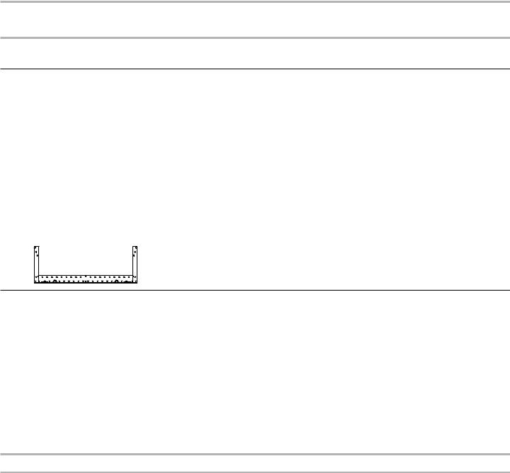
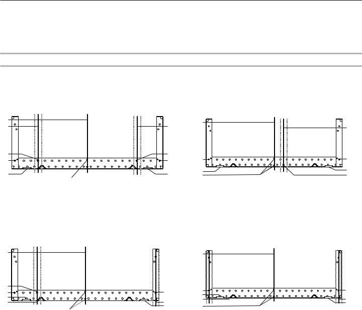
Possible Wall Stud Configurations
These depictions show examples of preferred installation configurations with the mounting plate.
No Wall Studs at End Holes |
|
|
No Wall Studs at End Holes |
|
Figure 1 |
|
|
Figure 2 |
|
B |
|
B |
|
|
C |
C |
|
||
|
C |
|||
|
|
|
||
D |
D |
|
A |
|
A |
A |
A |
||
E |
E |
E |
E |
|
F |
D |
|||
F |
|
|||
|
|
|
NOTE: If wall studs is within 6" (15.2 cm) of the vertical centerline (see “Mark Rear Wall” section), only recirculation or roof venting installation can be done.
Wall Studs at End Holes |
Wall Studs at End Holes |
Figure 3 |
Figure 4 |
|
|
B |
B |
|
D |
|
A,D |
|
A |
A,D |
||
E |
|||
E |
|
||
|
C |
||
C |
C |
||
|
|||
F |
E |
F |
|
|
|
A.End holes (on mounting plate)
B.Cabinet opening vertical centerline
C.Wall stud centerlines
D.Holes for lag screws
E.Support tabs
F.Mounting plate center markers
A,D
C
E
4
SECTION I only
This section is used for around 171/8" (43.5 cm) product height installation.
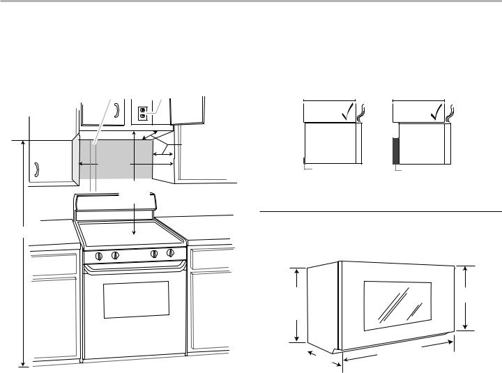
Installation Dimensions
NOTE: The grounded 3 prong outlet must be inside the upper cabinet. See the “Electrical Requirements” section.
A B
NOTE: To ensure good performance, do not obstruct top vent airflow. If cabinets are deeper than 14" (35.6 cm) but no more than 15" (38.1cm), use the bump out mounting kit replacing the I bar mounting plate from the wall. The bump out mounting kit (part # W11185746) is not provided and can be sourced independently from Whirlpool.
12" DEEPER
 14" 14"
 DEEPER
 15"
15"
|
12" (30.5 cm) min. |
|
|
|
14" (35.6 cm) max. |
|
|
30" |
upper cabinet and |
|
|
(76.2 cm) |
side cabinet depth |
|
|
min. |
I bar mounting plate |
Bump out mounting |
|
|
|
bracket |
|
30" |
|
|
|
(76.2 cm) |
|
|
|
typical* |
|
|
|
66" ( 167.6 cm) min. |
Product Dimensions |
||
*Overall depth of product will vary slightly depending on door |
|||
|
|||
|
design. |
|
|
|
/ |
|
171 8 |
" |
|
(43.5 cm) |
||
/ |
" |
|
+/-3 |
|
|
|
16 |
|
(0.5 cm) |
||
|
|
Up |
) |
||
|
|
to |
|||
|
16 |
3 |
|||
|
|
||||
|
(42. |
|
|
/4" |
|
5 |
cm |
||||
|
|
|
|
|
* |
161/4" (41.3 cm)
29/ |
|
.0 |
cm) |
|
"(76 |
|
|||
7 |
|
|
||
|
8 |
|
|
|
A.2" x 4" (5.1 cm x 10.2 cm) wall stud
B.Grounded 3 prong outlet
*30" (76.2 cm) is typical for 66" (167.6 cm) installation height. Exact dimensions may vary depending on type of range/cooktop below.
5
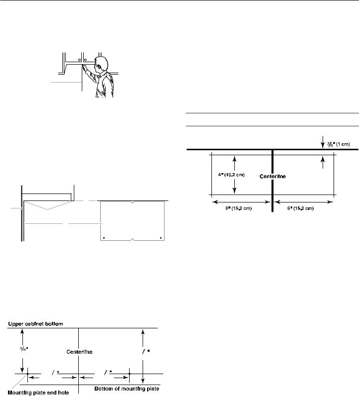
Mark Rear Wall
The microwave oven must be installed on a minimum of 1 wall stud, preferably 2, using a minimum of 1 lag screw, preferably 2.
1.Using measuring tape, find and clearly mark the vertical centerline of the opening.
A
2.Align the center markers on the wall template to the centerline on the wall, making sure it is level, and that the top of the wall template is butted up against the bottom edge of the upper cabinet.
NOTES:
■■ If the front edge of the upper cabinet is lower than the back edge, lower the wall template so that its top is level with the front edge of the cabinet.
■■ If the wall template is damaged or unusable, measure and mark the wall with the dimensions described in Step 4.
D |
A |
C |
B |
A.Rear wall
B.Wall Template
C.Top of wall template must align with front edge of cabinet
D.Front edge of upper cabinet
3.Holding the wall template in place, mark both holes in the lower corners and draw a horizontal line across the bottom edge of the wall template. These represent the wall plate’s end holes and bottom edge.
4.Remove the wall template and check the markings:
15 |
|
|
171 |
2 |
(39.7 cm) |
|
|
||
|
|
(44.5 cm) |
||
|
|
|
||
141 |
8 |
141 |
8 |
|
(35.9 cm) |
(35.9 cm) |
|
||
■■ The bottom edge line must be 171/2" (44.5 cm) from the bottom of the upper cabinet and must be level.
■■ The end holes must be 155/8" (39.7 cm) from the bottom edge of the upper cabinet and must be on a level line with each other. They must each be 141/8" (35.9 cm) from the centerline.
5.With the support tabs facing forward (see illustrations in the “Locate Wall Stud(s)” section), align the mounting plate center markers to the centerline on the wall, making sure its
bottom edge is aligned to the horizontal line drawn in Step 3 and that the end holes are properly marked. Make sure the mounting plate is level.
6.Holding the mounting plate in place, find the wall stud centerline(s) drawn in Step 2 of “Locate Wall Stud(s)” and mark at least 1, preferably 2 hole(s) through the mounting plate, closest to the wall stud centerline(s). See figures 1, 2, and/or 3 in “Possible Wall Stud Configurations” in the “Locate Wall Stud(s)” section. The blackened holes in the shaded areas are ideal hole locations.
7.Set the mounting plate aside.
Wall Venting Installation Only
Upper cabinet bottom
8.Mark the centerline 3/8" (1 cm) down from the bottom edge of the upper cabinet.
9.Using measuring tape, measure out 6" (15.2 cm) on both sides of the centerline, and mark.
10.Measure down 4" (10.2 cm) from the mark made in Step 8 and mark.
11.Using a straightedge, draw the 2 horizontal, level lines through the marks made in steps 8 and 10.
12.Draw the 2 vertical plumb lines down from the marks made in Step 9 to complete the 12" x 4" (30.5 x 10.2 cm) rectangle. This is the venting cutout area.
13.Cut a 3/4" (1.9 cm) hole in one corner of the cutout area.
14.Using a keyhole saw, cut out the venting cutout area.
6
Drill Holes in Rear Wall
In addition to being installed on at least 1 wall stud, the mounting plate must attach to the wall at both end holes. If the end holes are not over wall studs, use two 3/16-24 x 3" (7.62 cm) round-head bolts with toggle nuts; if 1 end hole is over a wall stud, use 1 lag screw and one 3/16-24 x 3" (7.62 cm) round-head bolt with toggle nut; or if both end holes are over wall studs, use 2 lag screws. Following are 3 installation configurations.
Installation for No Wall Studs at End Holes (Figures 1 and 2)
1.Drill 5/8" (1.6 cm) holes through the wall at both end holes marked in Step 3 of the “Mark Rear Wall.”
2.Drill 3/16" (5 mm) hole(s) into the wall stud(s) at the hole(s) marked in Step 6 of the “Mark Rear Wall.” Refer to figures 1 and 2 in “Possible Wall Stud Configurations” in the “Locate Wall Stud(s)” section.
Installation for Wall Stud at One End Hole (Figure 3)
1.Drill a 3/16" (5 mm) hole into the wall stud at the end hole marked in Step 3 of the “Mark Rear Wall.”
2.If installing on a second wall stud, drill a 3/16" (5 mm) hole into the wall stud at the other hole marked in Step 6 of the “Mark Rear Wall.” Refer to Figure 3 in “Possible Wall Stud Configurations” in the “Locate Wall Stud(s)” section.
3.Drill a 5/8" (1.6 cm) hole through the wall at the other end hole.
Installation for Wall Studs at Both End Holes (Figure 4)
1.Drill 3/16" (5 mm) holes into the studs at the end holes marked in Step 3 of the “Mark Rear Wall.”
Attach Mounting Plate to Wall
NOTE: Secure the mounting plate to the wall at both end holes drilled into the wall studs and/or drywall using either 3/16-24 x 3" round-head bolts and toggle nuts or 1/4 x 2" lag screws.
Refer to illustrations in “Possible Wall Stud Configurations” in the “Locate Wall Stud(s)” section.
No Wall Studs at End Holes (Figures 1 and 2)
NOTE: The mounting plate must be secured to the wall on at least 1 wall stud as well as at both ends.
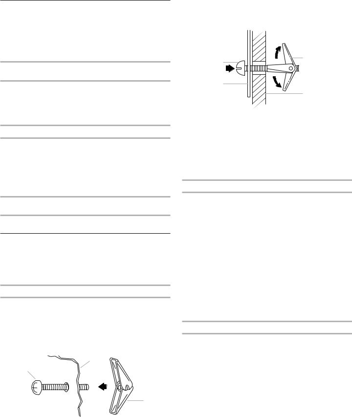
1.With the support tabs of the mounting plate facing forward, insert 3/16-24 x 3" round-head bolts through both end holes of mounting plate.
2.Start toggle nuts on bolts from the back of the mounting plate. Leave enough space for the toggle nuts to go through the wall and to open.
B
A
C
A. 3/16-24 x 3" round-head bolt
B.Mounting plate
C.Spring toggle nut
3.Position mounting plate on the wall.
4.Push the 2 bolts with toggle nuts through the drywall, and finger tighten the bolts to make sure toggle nuts have opened against drywall.
A |
C |
|
|
B |
|
|
D |
A. 3/16-24 x 3" round head bolt
B.Mounting plate
C.Spring toggle nut
D.Drywall
5.Insert lag screw(s) into the hole(s) drilled into wall stud(s) in Step 2 of “Installation for No Wall Studs at End Holes” in the “Drill Holes in Rear Wall” section.
6.Check alignment of mounting plate, making sure it is level.
7.Securely tighten all lag screws and bolts.
Wall Stud at One End Hole (Figure 3)
1.With the support tabs of the mounting plate facing forward, insert a 3/16-24 x 3" round-head bolt through the end hole that fits over the 5/8" (1.6 cm) hole drilled in Step 3 of “Installation for Wall Stud at One End Hole” in the “Drill Holes in Rear Wall” section.
2.Start a toggle nut on the bolt from the back of the mounting plate. Leave enough space for the toggle nut to go through the wall and to open.
3.Position mounting plate on the wall.
4.Push the bolt with toggle nut through the drywall, and finger tighten the bolt to make sure toggle nut has opened against drywall.
5.Insert a lag screw into the remaining end hole.
6.If installing on a second wall stud, insert a lag screw into the other hole drilled in Step 2 of “Installation for Wall Stud at One End Hole” in the “Drill Holes in Rear Wall” section.
7.Check alignment of mounting plate, making sure it is level.
8.Securely tighten the lag screw(s) and bolt.
Wall Studs at Both End Holes (Figure 4)
1.Position mounting plate on the wall.
2.Insert lag screws into both end holes.
3.Check alignment of mounting plate, making sure it is level.
4.Securely tighten the lag screws.
7
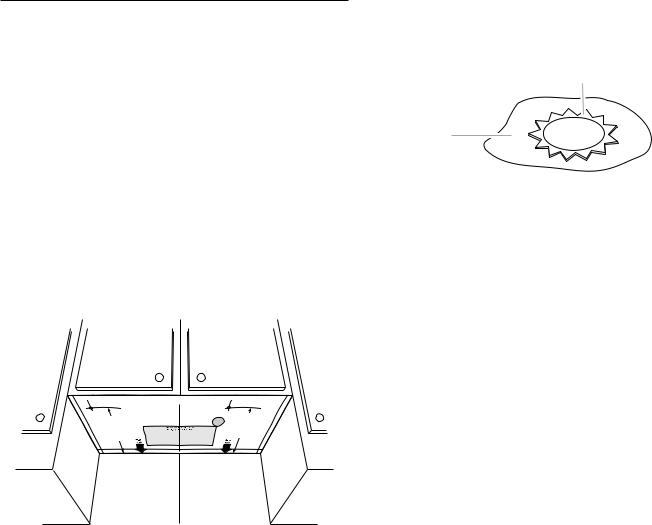
Prepare Upper Cabinet
1.Disconnect power to outlet.
2.Remove all contents from upper cabinet.
3.Place Upper Cabinet Template against the bottom of the upper cabinet, and attach with tape or thumbtacks. Make sure the template centerline aligns with the vertical centerline on the rear wall.
The “rear wall” arrows must be against the rear wall so that the holes cut into the upper cabinet align with the holes in the top of the microwave oven.
NOTES:
■■ If the upper cabinet has a frame around it, trim the template edges so that it fits inside the frame, against the upper cabinet bottom. The template has trim lines to use as guides.
■■ If the wall behind the microwave oven (as installed) has a partial wall covering (for example, tile backsplash), be sure the “Rear Wall” arrows align to the thickest part of the rear wall (for example, the thickness of the tiles rather than the drywall).
4.Make sure the 11" (27.9 cm) dimension from the rear wall to points “D” and “E” on the template is maintained.
Upper-cabinet template
D 11" |
|
G E 11" |
(27.9 cm) |
F |
(27.9 cm) |
|
|
5.Cut the 11/2" (3.8 cm) diameter hole at the circular shaded area “G” on the template. This hole is for the power supply cord.
NOTE: If upper cabinet is metal, the supply cord bushing needs to be installed around the supply cord hole as shown.
B
A
A.Metal cabinet
B.Power supply cord bushing
6.Drill 3/8" (1 cm) holes at points “D” and “E” on the template. These are for two -20 x 3" bolts and washers used to secure the microwave oven to the upper cabinet.
For Roof Venting Installation Only:
7.Cut 3/4" (1.9 cm) hole at one corner of the shaded rectangular area “F” on Upper Cabinet Template.
8.Using a keyhole saw, cut out the rectangular area.
8

SECTION II only
This section is used for around 105/16" (26.2 cm) product height installation.
Installation Dimensions
NOTE: The grounded 3 prong outlet must be inside the upper cabinet. See the “Electrical Requirements” section.
A B
NOTE: To ensure good performance, do not obstruct top vent airflow. If cabinets are deeper than 14" (35.6 cm) but no more than 15" (38.1cm), use the bump out mounting kit replacing the mounting plate from the wall. The bump out mounting kit (part # W11185746) is not provided and can be sourced independently from Whirlpool.
12" DEEPER
 14" 14"
 DEEPER
 15"
15"
30" (76.2 cm) min.
24" (61 cm) typical*
60" ( 152.4 cm) min.
12" (30.5 cm) min.
14" (35.6 cm) max.
upper cabinet and side cabinet depth
mounting plate |
Bump out mounting |
|
|
|
bracket |
Product Dimensions
*Overall depth of product will vary slightly depending on door design.
10 |
" |
(26.2cm) |
|
18" |
) |
. |
|
(45 5cm |
|
10 |
" |
(26.2 cm) |
|
|
|
|
) |
|
|
cm |
|
|
.0 |
|
|
29 |
"(76 |
|
|
A.2" x 4" wall stud
B.Grounded 3 prong outlet
*24" (61 cm) is typical for 60" (152.4 cm) installation height. Exact dimensions may vary depending on type of range/ cooktop below.
Mark Rear Wall
The microwave oven must be installed on a minimum of 1 wall stud, preferably 2, using a minimum of 1 lag screw, preferably 2.
1.Using measuring tape, find and clearly mark the vertical centerline of the opening.
A
A.Centerline
2.Align the center markers on the mounting template to the centerline on the wall, making sure it is level, and that the top of the mounting template is butted up against the bottom edge of the upper cabinet.
NOTES:
■■ If the front edge of the upper cabinet is lower than the back edge, lower the mounting template so that its top is level with the front edge of the cabinet.
■■ If the mounting template is damaged or unusable, measure and mark the wall with the dimensions described in Step 4.
D
A
C
B
A.Rear wall
B.Mounting Template
C.Top of mounting template must align with front edge of cabinet
D.Front edge of upper cabinet
3.Holding the mounting template in place, mark both holes in the lower corners and draw a horizontal line across the
bottom edge of the mounting template. These represent the mounting plate’s end holes and bottom edge.
9

4. Remove the mounting template and check the markings:
83 4 |
|
|
101 2 |
|
|
|
|
141 |
8 |
141 |
8 |
(35.9 cm) |
(35.9 cm) |
||
■■ The bottom edge line must be 101/2" (26.6 cm) from the bottom of the upper cabinet and must be level.
■■ The end holes must be 83/4" (22.3 cm) from the bottom edge of the upper cabinet and must be on a level line with each other. They must each be 143/16" (36 cm) from the centerline.
5.With the support tabs facing forward (see illustrations in the “Locate Wall Stud(s)” section), align the mounting plate center markers to the centerline on the wall, making sure its
bottom edge is aligned to the horizontal line drawn in Step 3 and that the end holes are properly marked. Make sure the mounting plate is level.
6.Holding the mounting plate in place, find the wall stud centerline(s) drawn in Step 2 of “Locate Wall Stud(s)” and mark at least 1, preferably 2 hole(s) through the mounting plate, closest to the wall stud centerline(s). See figures 1, 2, and/or 3 in “Possible Wall Stud Configurations” in the “Locate Wall Stud(s)” section. The blackened holes in the shaded areas are ideal hole locations.
7.Set the mounting plate aside.
Wall Venting Installation Only
8.Mark the centerline 3/8" (1 cm) down from the bottom edge of the upper cabinet.
9.Using measuring tape, measure out 6" (15.2 cm) on both sides of the centerline, and mark.
10.Measure down 4" (10.2 cm) from the mark made in Step 8 and mark.
11.Using a straightedge, draw the 2 horizontal, level lines through the marks made in steps 8 and 10.
12.Draw the 2 vertical plumb lines down from the marks made in Step 9 to complete the 12" x 4" (30.5 x 10.2 cm) rectangle. This is the venting cutout area.
13.Cut a 3/4" (1.9 cm) hole in one corner of the cutout area.
14.Using a keyhole saw, cut out the venting cutout area.
10
Drill Holes in Rear Wall
In addition to being installed on at least 1 wall stud, the mounting plate must attach to the wall at both end holes. If the end holes are not over wall studs, use two 3/16-24 x 3" roundhead bolts with toggle nuts; if 1 end hole is over a wall stud, use 1 lag screw and one 3/16-24 x 3" round-head bolt with toggle nut; or if both end holes are over wall studs, use 2 lag screws. Following are 3 installation configurations.
Installation for No Wall Studs at End Holes (Figures 1 and 2)
1.Drill 5⁄8" (1.6 cm) holes through the wall at both end holes marked in Step 3 of “Mark Rear Wall.”
2.Drill 3⁄16" (4.8 mm) hole(s) into the wall stud(s) at the hole(s) marked in Step 6 of “Mark Rear Wall.” Refer to figures 1 and 2 in “Possible Wall Stud Configurations” in “Locate Wall Stud(s)” section.
Installation for Wall Stud at One End Hole (Figure 3)
1.Drill a 3⁄16" (4.8 mm) hole into the wall stud at the end hole marked in Step 3 of “Mark Rear Wall.”
2.If installing on a second wall stud, drill a 3⁄16" (4.8 mm) hole into the wall stud at the other hole marked in Step 6 of “Mark Rear Wall.” Refer to Figure 3 in “Possible Wall Stud Configurations” in “Locate Wall Stud(s)” section.
3.Drill a 5⁄8" (1.6 cm) hole through the wall at the other end hole.
Installation for Wall Studs at Both End Holes (Figure 4)
1.Drill 3⁄16" (4.8 mm) holes into the studs at the end holes marked in Step 3 of “Mark Rear Wall.”
Attach Mounting Plate to Wall
NOTE: Secure the mounting plate to the wall at both end holes drilled into the wall studs and/or drywall using either 3/16-24 x 3" round-head bolts and toggle nuts or 1/4x 2" lag screws.
Refer to illustrations in “Possible Wall Stud Configurations” in “Locate Wall Stud(s)” section.
No Wall Studs at End Holes (Figures 1 and 2)
NOTE: The mounting plate must be secured to the wall on at least 1 wall stud as well as at both ends.
1.With the support tabs of the mounting plate facing forward, insert 3/16-24 x 3" round-head bolts through both end holes of mounting plate.
2.Start toggle nuts on bolts from the back of the mounting plate. Leave enough space for the toggle nuts to go through the wall and to open.
B
A
C
A.3/16-24 x 3" round-head bolt
B.Mounting plate
C.Spring toggle nut
3.Position mounting plate on the wall.
4.Push the 2 bolts with toggle nuts through the drywall, and finger tighten the bolts to make sure toggle nuts have opened against drywall.
A |
C |
|
|
B |
|
|
D |
A.3/16-24 x 3" round-head bolt
B.Mounting plate
C.Spring toggle nut
D.Drywall
5.Insert lag screw(s) into the hole(s) drilled into wall stud(s) in Step 2 of “Installation for No Wall Studs at End Holes” in the “Drill Holes in Rear Wall” section.
6.Check alignment of mounting plate, making sure it is level.
7.Securely tighten all lag screws and bolts.
Wall Stud at One End Hole (Figure 3)
1.With the support tabs of the mounting plate facing forward, insert a 3/16-24 x 3" round-head bolt through the end
hole that fits over the 5/8" (1.6 cm) hole drilled in Step 3 of “Installation for Wall Stud at One End Hole” in the “Drill Holes in Rear Wall” section.
2.Start a toggle nut on the bolt from the back of the mounting plate. Leave enough space for the toggle nut to go through the wall and to open.
3.Position mounting plate on the wall.
4.Push the bolt with toggle nut through the drywall, and finger tighten the bolt to make sure toggle nut has opened against drywall.
5.Insert a lag screw into the remaining end hole.
6.If installing on a second wall stud, insert a lag screw into the other hole drilled in Step 2 of “Installation for Wall Stud at One End Hole” in the “Drill Holes in Rear Wall” section.
7.Check alignment of mounting plate, making sure it is level.
8.Securely tighten the lag screw(s) and bolt.
Wall Studs at Both End Holes (Figure 4)
1.Position mounting plate on the wall.
2.Insert lag screws into both end holes.
3.Check alignment of mounting plate, making sure it is level.
4.Securely tighten the lag screws.
11
Loading...