


Whirlpool UXT2030ADB, UXT2030ADW, UXT3030ADB, UXT3030ADW, UXT4030ADB Installation Instructions
...
RANGE HOOD INSTALLATION INSTRUCTIONS
FOR ADA COMPLIANCE
For questions about features, operation/performance, parts, accessories, or service, call: 1-800-253-1301. In Canada, for assistance, installation, and service, call: 1-800-607-6777.
Residential range hoods can be installed to comply with Sections 308 and 309 of ADA Guidelines when used with appropriately mounted controls installed at 15" (38.1 cm) to 40" (101.6 cm) above the floor, and control access should not require reaching over a cooking appliance.
The following range hoods can work in an ADA-compliant situation when the range hood is wired to operate from a dedicated standard electrical wall switch. To facilitate this application, share the information on the following pages with your electrician when preparing for the installation.
NOTE: All the models can be controlled only by one remote switch. The switch activates or deactivates the motor and the light of the hood.
Two-Speed Range Hoods |
Intermediate Range Hoods |
Three-Speed Range Hoods |
(with rocker switch) |
(with rotary switch) |
(with push buttons) |
|
|
|
■■ |
UXT20 |
■■ |
UXT42 |
■■ |
UXT52 |
■■ |
UXT30 |
|
|
|
|
■■ |
UXT40 |
|
|
|
|
■■ |
UXT41 |
|
|
|
|
|
|
|
|
■■ |
WVU37U |
INSTALLATION REQUIREMENTS
Tools and Parts
Tools Needed
Wire stripper |
#2 Phillips |
Flat-blade |
|
screwdriver |
screwdriver |
Parts Needed
UL Listed/CSA |
UL Listed/CSA |
UL Listed #14 |
|||||||
Approved wire |
|
Approved |
(minimum) |
||||||
connectors |
|
1/2" (13 mm) |
3 wire cable |
||||||
|
|
|
|
|
strain relief |
|
|
||
|
|
|
|
|
|
|
|
|
|
|
|
|
|
|
|
|
|
|
|
|
|
|
|
|
|
|
|
|
|
|
|
|
|
|
|
|
|
|
|
|
|
|
|
|
|
|
|
|
|
|
|
|
|
|
|
|
|
|
|
Electrical Requirements
Observe all governing codes and ordinances.
Ensure that the electrical installation is adequate and in conformance with National Electrical Code, ANSI/NFPA 70 (latest edition), or CSA Standards C22.1-94, Canadian Electrical Code, Part 1 and C22.2 No. 0-M91 (latest edition) and all local codes and ordinances.
If codes permit and a separate ground wire is used, it is recommended that a qualified electrician determine that the ground path is adequate.
A copy of the above code standards can be obtained from:
National Fire Protection Association
1 Batterymarch Park
Quincy, MA 02169-7471
CSA International
8501 East Pleasant Valley Road
Cleveland, OH 44131-5575
■■ A 120-volt, 60 Hz., AC-only, 15-amp fused electrical circuit is required.
UL Listed single pole |
UL Listed deep |
toggle light switch |
single-gang |
|
switch box |
W11108368A |
|
INSTALLATION INSTRUCTIONS
 WARNING
Electrical Shock Hazard Disconnect power before installing light switch.
Electrically ground range hood and light switch by connecting ground wire to the ground screw in the switch box.
Replace all parts and panels before operating.
Failure to do so can result in death or electrical shock.
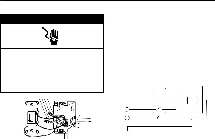
B A C D
F
I 

G
H
 E
E
A.White wires (N)
B.Black wires (L)
C.UL Listed wire connector
D.Green (or bare) ground wire
E.Home power supply cable #14 UL Approved cable
F.Range hood cable
G.UL Listed or CSA Approved 1/2" (13 mm) strain relief
H.Green ground screw
I.UL Listed single pole toggle light switch
1.Mount the switch box on the wall in an easily accessible area 15" (38 cm) to 40" (1 m) above the floor. Avoid reaching over the cooking surface.
For a single pole toggle light switch: Install a 31/2" (8.9 cm) deep single gang switch box.
2.Attach the power cable to the switch box.
Clamp wiring to switch box and unit using a UL Listed or CSA Approved 1/2" (13 mm) strain relief. Provide 6" (15.2 cm) leads inside box and fan for easier wiring.
3.Connect wiring.
General instructions for all models:
■■ Make sure both the single pole toggle light switch and the range hood are properly grounded.
■■ Make sure the ground wire is securely fastened to the single pole toggle light switch ground screw. Tighten ground screw.
■■ Use proper wire nut sizes for number and size of wires. ■■ Tighten screw terminals.
■■ Make electrical connections, following appropriate diagram.
|
|
RANGE HOOD |
|
SINGLE |
|
|
POLE |
|
|
LIGHT |
LOAD |
120 VAC |
SWITCH |
|
|
|
|
L |
BLACK |
|
|
|
NWHITE GRND
4.Mount single pole toggle light switch in switch box.
Tuck wires into switch box and fasten the control to box using attached screws.
5.Attach switch plate.
Fasten the switch plate to the control using the short screws from the parts bag.
6.Set the fan speed and light on the range hood to your preference. The light switch will turn the range hood on and off using your settings.
 Loading...