


Whirlpool UXA0024AXW, UXA0024AXS, UXA0024AXQ, UXA0024AXB, AMC5143AAW Installation Instructions
...INSTALLATION INSTRUCTIONS
BUILT-IN KIT MODEL UXA0024AXB/Q/W/S
IMPORTANT:This Built-In Kit is desinged for and approved only for those AMANA AMC5143AAB/W/Q/S Microwave Ovens specifying Built-In Kit UXA0024AXB/Q/W/S on rating label on the oven.
CAUTION: THIS OVEN REQUIRES INSTALLATION INTO A CABINET STRUCTURE ONLY. THIS
OVEN IS NOT DESIGNED FOR USE IN NON-CABINET INSTALLTIONS OR FREE-
STANDING APPLICATIONS ADJACENT TO (WITHIN 2 FEET OF) ANY GAS OR ELECTRIC RANGE, COOKTOP OR OVEN.
The cabinet or wall opening must be within the following dimensions :
WIDTH |
22-13/64" to 22-19/64" |
HEIGHT |
16-15/16" to 17-1/64" |
DEPTH |
15-3/4" minimum |
PLEASE READ THESE INSTRUCTIONS THOROUGHLY BEFORE BEGINNING INSTALLATION!
8
|
11 |
|
Screw Information |
|
|
10 |
Part |
|
Specification |
|
|
|
|
Screw-A |
TH,+, M4,L16, ZPC(YEL), MSMR1 |
||
Screw A Type |
Screw B Type |
Screw-B |
WE,TH,+,M4,L12,ZPC(YEL),WASHER |
||
|
|
|
|
||
|
|
9 |
NO. PART NAME |
Q’TY |
|
|
6 |
5 |
|
PART CODE |
|
|
12 |
1 |
DUCT UPPER |
1 |
|
|
|
||||
|
|
|
2 |
DUCT BOTTOM |
1 |
|
|
|
3 |
DUCT BACK A |
1 |
|
|
|
4 |
DUCT BACK B |
1 |
7 |
|
1 |
5 |
DUCT-RAIL |
2 |
|
|
6 |
ASSY TRIM |
2 |
|
|
|
|
|||
|
|
|
7 |
TRIM -SIDE |
2 |
|
|
4 |
8 |
TRIM -CAP(L) |
2 |
|
|
3 |
9 |
TRIM -CAP(R) |
2 |
|
|
|
|||
|
|
2 |
10 |
SCREW A |
4 |
|
|
|
11 |
SCREW B |
17 |
|
|
|
12 |
CUSHION |
1(168mm) |
Be sure to DISCONNECT THE PLUG of the microwave oven from the electrical outlet before installing the built-in kit.
Remove the turntable tray from the oven cavity, if needed.

STEP 1 : CABINET OR WALL OPENING
Provide an opening in the wall or cabinet, as indicated in SKETCH 1.
The depth should be a minimum of 15-3/4". The floor of the opening should be constructed of plywood strong and thick enough to support the weight of the oven <about 50 lbs.> and installation job.
First, punch the 4-holes using the template, Place the Duct-Rail on the Bottom of the Cabinet. Coincide the Duct-Rail holes with the bottom holes of the Cabinet.
Screw the Duct-Rail using Screw B(4EA)
NOTE :
While the proper functioning of the oven does not require that opening be enclosed (with sides, ceiling and rear partition) this may be required by local code, and it is suggested that the local code be checked for any such requirement.
W |
22-13/64" to 22-19/64" |
W |
|
|
|
H |
16-15/16" to 17-1/64" |
|
|
|
|
D |
15-3/4" minimum |
D |
|
||
|
|
|
|
|
H |
|
|
SKETCH 1 |
STEP 2 : TRIM ASSEMBLY
Position the ASSY TRIM and SIDES as shown in SKETCH 2.
Make sure that the ASSY TRIM and SIDES are lined up properly to be neat and symmetrical. Then using Screw B(4EA), screw the parts together at screw locations shown in SKETCH 2.
SKETCH 2 |
STEP 3 : DUCT INSTALLATION a. Duct Bottom Installation
First, place the oven upside-down.
Attach the DUCT BOTTOM to the oven base using Screw B(4EA) as shown in SKETCH 3. Carefully return the oven to it's original position.
SKETCH 3
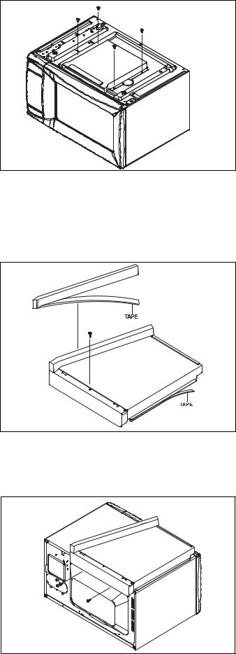
b.Duct Upper & Back A, B Installation
1.First, screw the Duct Upper & Duct Back-A using Screw B(1EA) and remove the Double-side tape of the Duct Upper. Remove the Double-Side tape of the Cushion.
Stick it to the Duct Upper & Duct Back-A along the Duct Upper & Duct Back-A.
Refer to the SKETCH 4.
SKETCH 4
2.Place the Assembled parts(Duct Upper & Duct Back A) on the Microwave Oven in SKETCH 5. Screw the Assembled parts(Duct Upper & Duct Back A) using Screw B(2EA).
Refer to the SKETCH 5.
SKETCH 5
 Loading...