


ARB 540-K/G/1
English
ENVIRONMENTAL HINTS
Do not throw the packing into the garbage: first sort out
the different materials (i.e.: steel, cardboard, polystyrene)
for recycling, following local regulations.
Conformity declaration
This appliance incorporates parts intended to come into
contact with foodstuffs in compliance with EEC directive 89/09/CEE.
Information
This appliance is free of CFC’s (refrigerant circuit contains
R134a) or free ofHFC’s(refrigerantcircuit contains R600a –
Isobutane). For more details, please refer to the rating
plate on the appliance.
For appliances with Isobutane (R600a)
The refrigerant Isobutane is a natural gas of high environmental compatibility but which is inflammable. Therefore,
it is essential to ensure that the ducts of the refrigerant circuit do not get damaged.
Ù
KNOW YOUR APPLIANCE
The appliance you have just bought combines refrigerator
and freezer compartments.
The
freezer compartment,
fect freezing of fresh and cooked foods, the production of
ice cubes and the storage of frozen foods.
The
refrigerator compartment
allows the storage of fresh foods and beverages.
Please read these instructions carefully, you will find the
description of your appliance and the useful hints to obtain
the best performance to store foods.
at the bottom, allows the per-
with automatic defrosting,
DESCRIPTION OF THE APPLIANCE
(Fig. of cover)
This combined “Maxi Combi” consists of two independent
compartments which operate with 2 separate c ompressors:
− Top compartment: Refrigerator
− Bottom compartment: Freezer
If required, it is possible to operate a single compartment
(refrigerator only or freezer only).
The description of the appliance hereunder allows you to
know your appliance in a short time.
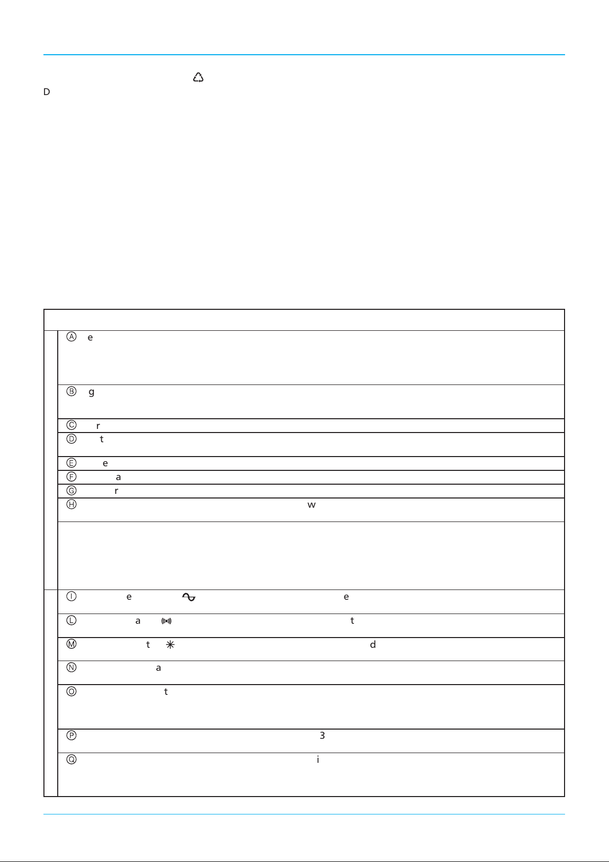
DESCRIPTION OF THE COMBINED REFRIGERATOR (Fig. 1 - internal cover)
Refrigerator thermostat control knob − it s witches on the a ppliance and adjusts the refrigerator
a
R
E
F
R
I
G
E
R
A
T
O
R
C
O
M
P
A
R
T
M
E
N
T
Light switch − it is operated automatically by the door opening/closing
b
Refrigerator compartment interior light − wi th a 15 W lamp al ready provided
c
Crystal shelves − removable and adjustable at different heights: they are
d
Crispers − sliding wide crispers for fruits and vegetables
e
Lower rack − butter compartment with door
f
Bottles rack − to store standard 1,5 l bottles: sliding bottle-stop
g
Top rack − with transparent balcony; it incorporates 2 removable
h
x Defrosting of the refrigerator compartment − th e refrige r ator compa r tment does not require any de-
temperature
− position “0”: refrigerator off
− position 2 - 3: med. cold temperature
− position 3 - 4: very cold temperature
and operates the switching on of the interior light of the refrigerator compartment
made of unbreakable crystal
egg-racks
frost operation as defrosting takes normally place dur-
ing the operation of the appliance.
F
R
E
E
Z
E
R
C
O
M
P
A
R
T
M
E
N
T
6
Alarm pilot lamp (l) − red light: it switches on when the freezer has not yet attai-
l
Fast freeze switch (÷) − when activated, the “yellow pilot lamp” switches o n; this
m
Freezer thermostat control knob − it controls the freezer compartment temperature; at first,
n
Freezer defrost water collector − the freezer compartment only requires defrosting at least
o
Freezer baskets − No3 sliding baskets on the refrigerating grids. Freeze fresh
p
Ventilation grid − this appliance is provided with a fan situated on the base,
q
light on indicates that the freezer is operating.
ned the correct operating temperature.
function has to be used when freezing fresh foods
adjust it on a med value.
once or twice a year when the frost which builds-up on the
freezer grids reaches a 2 - 3 mm thickness. See the freezer defrosting instructions.
foods using the top compartment (freezer coldest section).
which maintains the refrigerating cycle to a high performance.
Do not obstruct the air flow.
On/off freezer switch (M) − it switches on and off the freezer compartment: the green
i

GB
INSTALLATION (Fig. 2)
Ensure that the appliance is not damaged. Transit damages
must be reported to your dealer within 24 h of receipt of
the appliance. The appliance should not be installed close to
heat sources, central heating, cookers, boilers, sunlight, etc.
It must however be located in a well ventilated dry space.
Should this type of installation be unavoidable, please allow
the following side distances:
a) between appliance and any coal or gas stove: 30 cm min.
b)
between appliance and gas or electric cookers: 3 cm min.
You can install between the appliance and the cooker an
insulating plate, which is available by specialized dealers.
The appliance must stand level. Please follow the instructions given in the separate built-in instructions. Allow the
appliance to stand for one hour approx. prior to operating
it: in the meantime clean the inside with a solution of water
and vinegar (Fig. 3) and mount the accessories provided.
The appliance is fitted with an interior light situated on the
top of the refrigerator inner liner, with a 15 W lamp (Fig. 4).
Attention: Accessibility to the mains supply plug must be
guaranteed even after the installation to disconnect the
appliance in case of need. Contrarily, provide a two-pole
switch with a contact separation of 3 mm or more, situated
in an accessible position.
ELECTRICAL CONNECTION AND
OPERATION
This appliance has been designed, built and marketed in
compliance with:
- the safety targets of the “Low Voltage” EEC Directive
73/23;
- the protection requirements of the “EMC” EEC Directive 89/336 amended by EEC Directive 93/68.
Check that the voltage on the rating plate (Fig. 5),situated
inside the compartment, near the crisper, corresponds to
the voltage in your home.
The earthing of this appliance is compulsory by law. The
manufacturer will accept no liability for injury to persons or
damage to objects arising from the non-observance of this
requirement.
have the socket replaced by a qualified electrician. He
should also check that the section of the socket wires can
withstand the power absorbed by the appliance. The use
of adapters, multiple sockets and extension cords is not advisable. If absolutely necessary, use simple or multiple adapters and extension cords in compliance with local safety regulations, paying attention not to exceed the maximum
amperage, which is marked on the simple adaptors and on
extension cords and that of the total power marked on the
multiple adapters.
If the plug and the wall socket do not comply,
ELECTRICAL INFORMATION
“WARNING - T HIS APPLIANCE MUST BE EARTHED” (For
Great Britain only)
Fuse replacement.
If the mains lead of this appliance is fitted with a BS 1363A 13
amp fused plug, to change a fuse in this type of plug use an
A.S.T.A. approved fuse to BS 1362 type and proceed as follows:
1. Remove the fuse cover (A) and fuse (B).
2. Fit replacement 13A fuse into fuse cover.
3. Refit both into plug.
IMPORTANT:
ing a fuse and
used until a correct replacement is fitted.
Correct replacements are identified by the colour insert or
the colour embossed in words on the base of the plug.
Replacement fuse covers are available from your local electrical store.
The f use c over must be refitted when changif the fuse cover is lost the plug must not be
CONNECTION TO A REWIREABLE PLUG
If the fitted plug is not suitable for your socket outlet, then
it should be cut off and disposed of in order to avoid a
possible shock hazard should it be inserted into a 13A socket elsewhere. A suitable altenative plug should then be
fitted to the cable. The wires in this mains lead are coloured
in accordance with the following code;
BLUE - “NEUTRAL” (“N”)
BROWN - “LIVE” (“L”)
GREEN AND YELLOW - “EARTH” (“E”)
1.
The GREEN AND YELLOW wire must be connected to the
terminal in the plug which is marked with the letter “E” or by
the Earth symbol
2. The BLUE wire must be connected to the terminal
which is marked with the letter “N” or coloured black.
3. The BROWN wire must be connected to the terminal
which is marked with the letter “L” or coloured red.
GREEN AND
YELLOW (“E”)
BLUE (“N”)
Connection to a
typical 13 amp plug
For the Republic of Ireland only
The information given in respect of Great Britain will frequently apply, but a third type of plug and socket is also
used, the 2-pin, side earth type. In this case, the wire which
is coloured GREEN AND YELLOW must be connected to
the EARTH contact, and the other two wires to the two
pins, irrespective of colour. The supply to the socket must
befittedwitha16ampfuse.
To switch on the refrigerator compartment, set the knob
(Fig. 1 -
When the appliance is operating, the interior light switches
on opening the refrigerator door.
To switch on the freezer compartment, press switch
situated on the green luminous centre facia.
The green pilot lamps
switch on. The green pilot lamp remains always alight and
indicates the operation of the freezer.
The red alarm pilot lamp remains alight until the correct
operation temperature of the freezer has been attained.
Then this lamp switches on only when the temperature inside the refrigerator rises due to frequent door opening or
to prolonged door opening, or when the appliance has
been loaded with fresh food to be frozen.
In this case, switch on the fast freeze switch (M) (Fig. 1)
until the red pilot lamp
) to a middle position 2 - 3.
A
or coloured green or green and yellow.
4
BROWN (“L”)
CABLE CLAMP.
and the red pilot lampl(Fig. 1)
i
switches off automatically.
l
M
i
,
7
 Loading...