


D13F
Table of contents
 Loading...
Foreword
This booklet is part of a complete service manual. Read the
foreword in the service manual.
WARNING
Always read the booklet Safety before proceeding.
PUB 2012.10
1


Table of contents
03 SPECIFICATIONS
030 General
Tightening torque, cylinder head ................................................................ 6
Engine, specification
General ..................................................................................................... 6
Cylinder block, specifications ...................................................................... 7
Engine transmission, tightening torque ....................................................... 7
Tightening torques .................................................................................... 7
Timing gear casing ................................................................................... 9
Tightening torques, flywheel housing WLO/EXC .................................... 11
Tightening torques, timing gear plate ..................................................... 11
Engine transmission, specification ............................................................ 12
Rocker arm shaft, tightening torques ........................................................ 13
Valve mechanism, specifications .............................................................. 14
Valve mechanism, tightening torques ....................................................... 16
Tightening torques, valve cover ................................................................ 16
Oil sump, tightening torque ....................................................................... 16
Oil cooler, tightening torques .................................................................... 17
Oil cooler ................................................................................................. 17
Oil cooler, cover ...................................................................................... 17
Cylinder block, tightening torques ............................................................. 18
Engine mount incl. bracket ..................................................................... 18
Ladder frame .......................................................................................... 19
Inlet ......................................................................................................... 19
Tightening torque, fuel system .................................................................. 21
Exhaust manifold, tightening torques ........................................................ 21
Turbocharger, tightening torques .............................................................. 21
Crank mechanism, specifications ............................................................. 23
Crankshaft, tightening torques .................................................................. 25
Flywheel, tightening torques ..................................................................... 26
Belt pulley/vibration damper, tightening torques ....................................... 27
................................................................................... 6
21 ENGINE
210 General, common info about 211 - 218
Engine, mounting in work stand ................................................................ 28
Engine, dismantling .................................................................................. 32
Cylinder liners, removing ........................................................................ 39
Engine, assembling .................................................................................. 40
Cylinder liners, installing ......................................................................... 41
Crankshaft, installing .............................................................................. 43
Pistons, installing .................................................................................... 44
Installing timing gear plate ...................................................................... 45
Flywheel housing .................................................................................... 49
Crankshaft seal, rear .............................................................................. 50
Front crankshaft seal .............................................................................. 51
Speed (rpm) sensor, adjusting ................................................................ 54
Engine, removing from work stand ........................................................... 56
211 Cylinder head
Cylinder head, removing ........................................................................... 59
Cylinder head, reconditioning ................................................................... 62
Installing in work stand ........................................................................... 62
Valves, removing .................................................................................... 63
Sleeve for unit injector, removing ........................................................... 64
Tap out with drift ..................................................................................... 65
Pull out with puller ................................................................................... 65
Valve guide, checking ............................................................................. 67
Valve guides, changing ........................................................................... 68
3

Injector sleeve, installing ......................................................................... 69
Cylinder head, checking for leaks
Valve seat, checking ............................................................................... 73
Valve seat, cleaning soot and grinding ................................................... 73
Valve seat, changing .............................................................................. 73
Valves, grinding ...................................................................................... 74
Cylinder head, assembling ..................................................................... 74
Cylinder head, fitting ................................................................................. 76
212 Cylinder block with crankcase ventilation
Cylinder block, liners removed, milling of all liner locations ...................... 82
214 Valve mechanism
Valves, adjusting ....................................................................................... 88
Inlet valves, checking and adjusting ....................................................... 89
Unit injectors, adjusting ........................................................................... 89
Exhaust valves, checking and adjusting ................................................. 90
...........................................................
22 LUBRICATING SYSTEM
223 Oil cooler
Oil cooler, leakage check .......................................................................... 91
71
4

GENERAL
03 SPECIFICATIONS
030 General
5
13
36 35
9
28 27
6
22 21
1
15 16
3
23 24
7
31 32
11
14
38 37
10
30 29
4
18 17
2
19 20
5
25 26
8
33 34
12
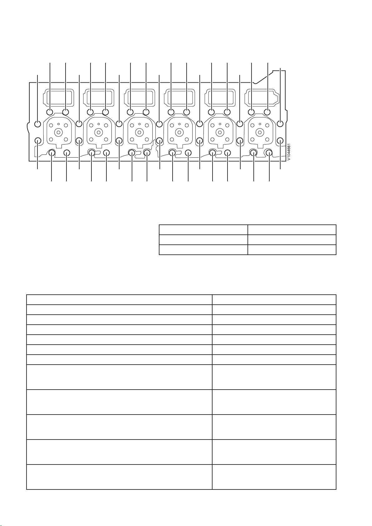
Fig.1 Cylinder head, D13
Tightening torque, cylinder head
NOTE!
Tighten the bolts in the sequence shown in the figure.
Step 1 100±5Nm(74±3.7 lbf ft)
Step 2 120±5° Angle-tightening
Step 3 90±5° Angle-tightening
Engine, specification
General
D13 F
Number of cylinders 6
Cylinder bore 131 mm (5.16 in)
Stroke 158 mm (6.22 in)
Displacement 12.78 litres (3.38 US gal)
Injection order 1–5–3–6–2–4
Compression ratio 18, 5:1
Low idle
EXC
WLO
High idle
EXC
WLO
Max. full load rpm
EXC
WLO
Weight, engine
EXC
WLO
Total length
EXC
WLO
13.33 r/s (800 rpm)
11.67 r/s (700 rpm)
28.33 r/s (1700 rpm)
31.67 r/s (1,900 rpm)
31.67 r/s (1,900 rpm)
35 r/s (2,100 rpm)
1,330 kg (3,042 lbs)
1,330 kg (3,042 lbs)
1 585 mm (62.4 in)
1460 mm (57.5 in)
6
D13 F
Width
EXC
WLO
Height
EXC
WLO
789 mm (31.1 in)
1077 mm (42.4 in)
1 250 mm (49.2 in)
1 215 mm (47.8 in)
Cylinder block, specifications
Length 1 052 mm (41.42 in)
Height, upper block face-crankshaft centre 422 mm (16.6 in)
Height, lower block face-crankshaft centre 120 mm (4.72 in)
Cylinder liners
Type Wet, replaceable
Sealing surface's height over cylinder block's face 0.15 – 0.21 mm (0.0059 — 0.0083 in)
Number of seal rings per cylinder liner 3
Engine transmission, tightening torque
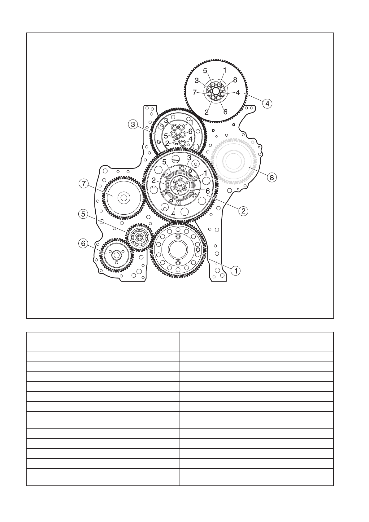
Tightening torques
NOTE!
Tighten in the order shown in the figure.
7
V1071860
Fig.2
Gears: Tightening torque:
1. Drive gear, crankshaft 24±4 Nm (18±3 lbf ft)
2. Transfer gear, outer gear:
step 1: 25±3 Nm (18.4±2.2 lbf ft)
step 2: angle-tightening 110±5°
3. Transfer gear, adjustable:
step 1: 35±4 Nm (25.8±2.95 lbf ft)
step 2: angle-tightening 120° ±5°
4. Gear, camshaft: Vibration damper's 8.8-bolts may not
be reused.
temporarily: 10 Nm (7.5 lbf ft)
step 1: 45±5 Nm (33±4 lbf ft)
step 2: Angle-tightening 90° ±5°
5. Transfer gear 140±10 Nm (103±7.4 lbf ft)
6. Drive gear, lubrication oil pump for power take-off and
100±10 Nm (74±7.4 lbf ft)
fuel feed pump
8
7. Drive gear, compressor 200+50/-0 Nm (148+37/-0 lbf ft)
V1088409
8. Not used
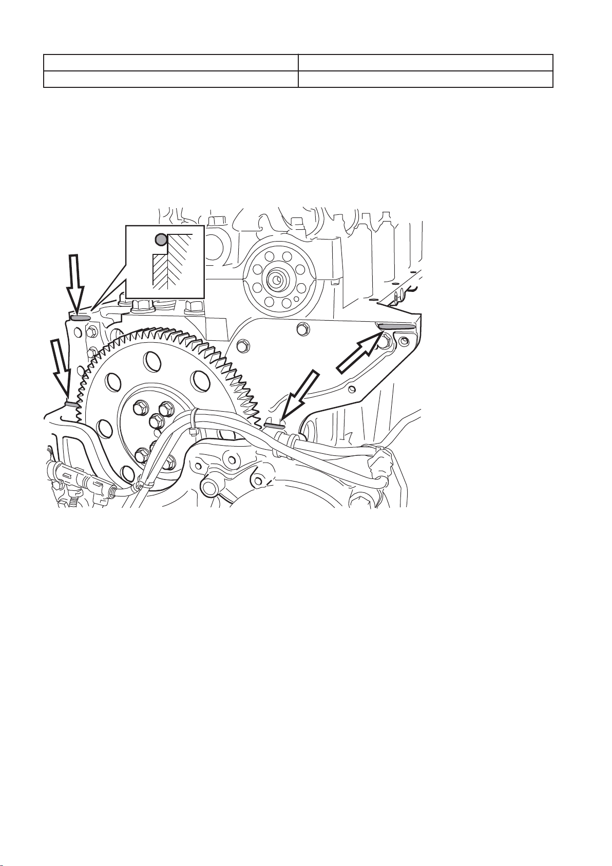
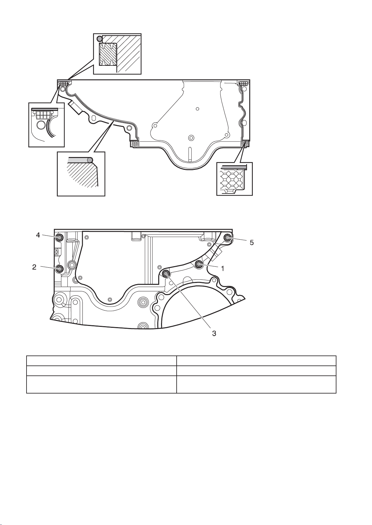
Timing gear casing
Apply a
2 mm (0.08 in) thick bead of sealant (part no. 11713514)
as shown in the figures on the timing gear casing's contact face
against the cylinder head. Install the rubber seals.
NOTE!
The timing gear casing must be installed and torque-tightened
within 20 minutes of applying the sealant.
Fig.3
9
V1088411
Fig.4
V1088408
Fig.5 Tightening torques, upper timing gear casing
Timing gear casing (upper)
Step 1: Fasten the casing with the bolts 1 and 2. 4±1 Nm (3±0.74 lbf ft)
Tighten the bolts in the order shown in the above
24±4 Nm (18±3 lbf ft)
figure.
10
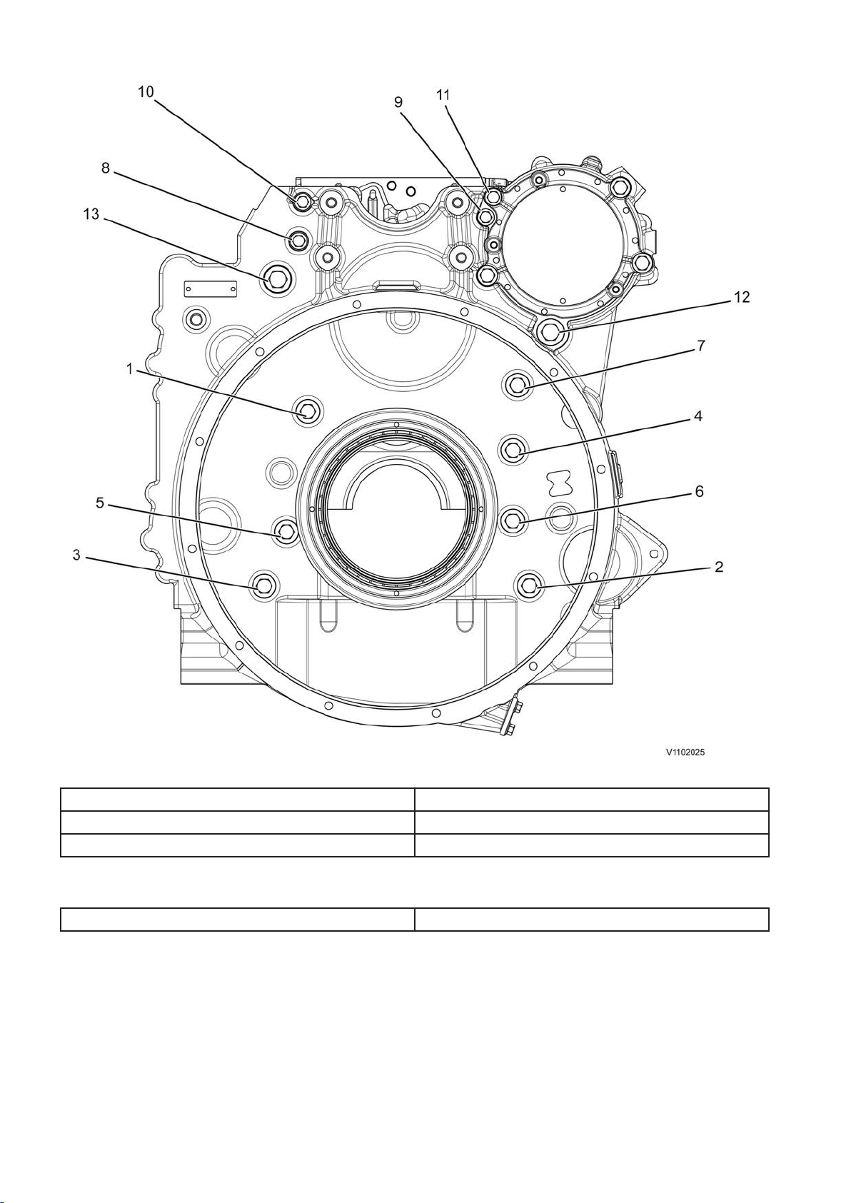
Tightening torques, flywheel housing WLO/EXC
Fig.6 Flywheel housing, WLO/EXC
M14-bolts 160 ± 10 Nm (118 ± 7.4 lbf ft)
M10-bolts 48 ±8 Nm (35.4 ±5.9 lbf ft)
M16-bolts 100±5 Nm (74±3.7 lbf ft)
Tightening torques, timing gear plate
M8-bolts 28±4 Nm (21±3 lbf ft)
11
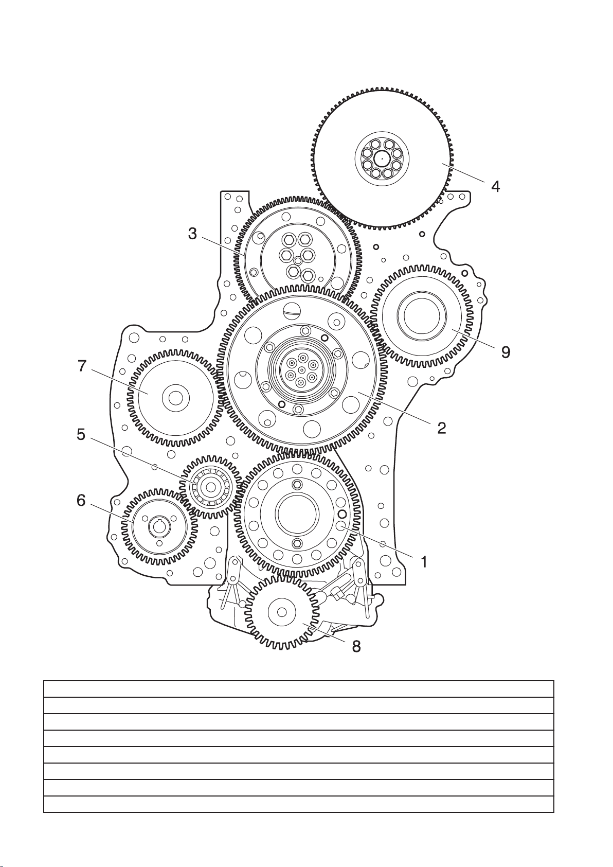
Engine transmission, specification
V1071840
Fig.7
Gears:
1. Drive gear, crankshaft
2. Transfer gears: outer and inner gear
3. Transfer gear (adjustable)
4. Drive gear and vibration damper, camshaft
5. Transfer gear
6. Drive gear, lubrication oil pump for fuel feed pump
7. Drive gear, compressor
12
8. Drive gear, lubrication oil pump
V1082177
9. Not used
Gear flank clearance (backlash), adjustable transfer
0.05–0.15 mm (0.0019–0.0059 in)
gear to camshaft's drive gear
Gear flank clearance (backlash), oil pump's drive gear 0.05–0.41 mm (0.0019–0.016 in)
Gear flank clearance (backlash), other drive gears 0.05–0.20 mm (0.0019–0.0078 in)
For checking camshaft installation:
Valve lift, inlet valve, cylinder 1 at 6° after TDC 1.6 ± 0.3 mm (0.063 ± 0.012 in)
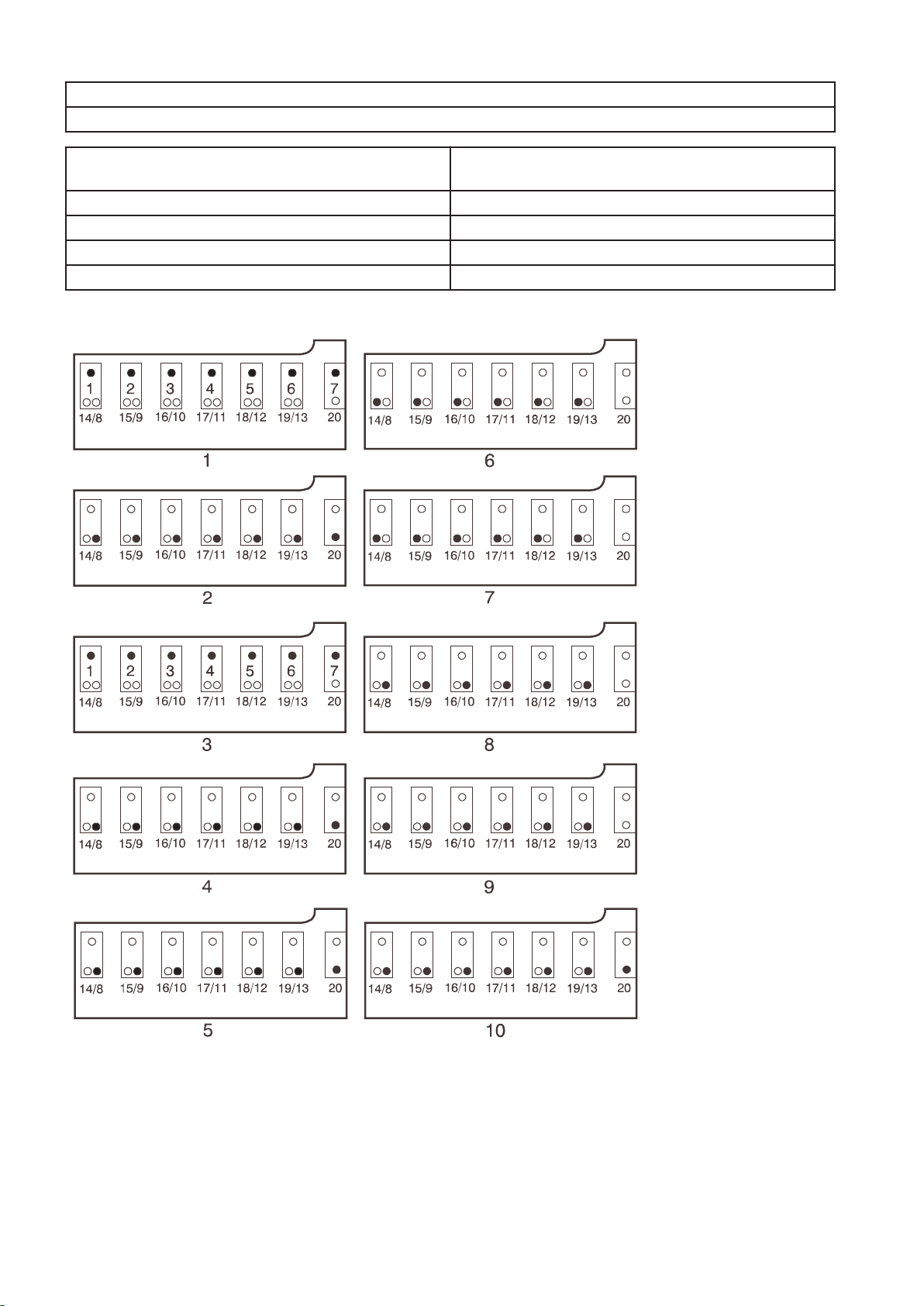
Rocker arm shaft, tightening torques
Fig.8
13
Camshaft: (camshaft and bearing caps in place)
Fit a mandrel to the number 7 bearing bracket to protect the
guide sleeve.
Step 1: Tighten screws 1–7 25±3 Nm (18±2.2 lbf ft)
Step 2: (with shorter additional screws) Tighten screws 8–13 and
60±5 Nm (44±3.7 lbf ft)
20..... 60±5 Nm
Step 3: Angle tighten screws 1-7 90°±5°
Step 4: Remove the extra screws 8–13 and 20
Remove the mandrel from the number 7 bearing bracket.
Rocker arm shaft: (Rocker arm shaft in place)
Step 5: Tighten screws 8 - 13 and 20 in steps in the order 11,
60±5 Nm (44±3.7 lbf ft)
10, 12, 9, 13, 8, 20.
Step 6: Tighten screws 14–19 25±3 Nm (18±2.2 lbf ft)
Step 7: Angle tighten screws 14-19 120°±5°
Step 8: Untighten bolts 8–13
Step 9: Tighten screws 8-13 25±3 Nm (18±2.2 lbf ft)
Step 10: Angle tighten bolts 8 – 13 and 20 120°±5°
Valve mechanism, specifications
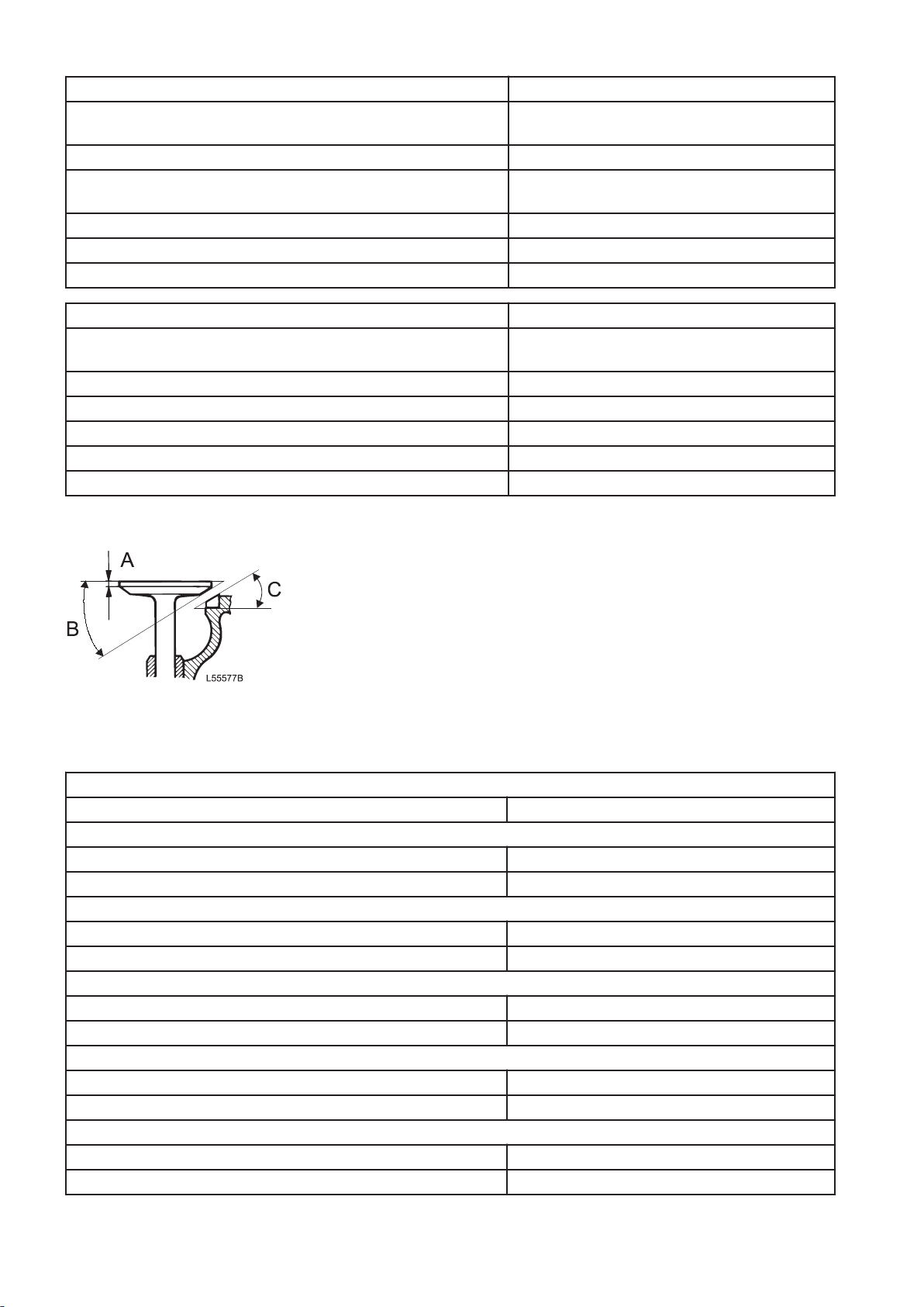
Fig.9
1 Valve disc, thickness (A)
2 Valve's seat angle (B)
3
Valve seat's angle (C)
Valves
Valve arrangement Top valves
Valve disc, diameter
Inlet 42 mm (1.65 in)
Exhaust 40 mm (1.57 in)
Valve stem, diameter
Inlet 7.968 mm (0.3137 in)
Exhaust 7.955 mm (0.3131 in)
Valve's seat angle
Inlet 24.5°
Exhaust 39.5°
Seat's angle in cylinder head
Inlet 25°
Exhaust 40°
Valve disc, thickness
Inlet 2.766 mm (0.108 in)
Exhaust 2.163 mm (0.085 in)
14
Valve clearance, cold engine
Inlet valves, checking value 0.15 — 0.25 mm (0.0059 — 0.0098 in)
Inlet valves, setting value 0.20 mm (0.0079 in)
Exhaust valves, checking value 0.75 — 0.85 mm (0.029 — 0.033 in)
Exhaust valves, setting value 0.8 mm (0.031 in)
Brake rocker arm, checking value 2.78 – 2.92 mm (0.109 – 0.114 in)
Brake rocker arm, setting value 2.85 mm (0.112 in)
Checking value without feeler gauge on valve yoke Min. 3.20 mm (0.126 in)
Distance between valve disc and cylinder head's face:
Inlet
Max. 1.85 mm (0.072 in)
Min. 1.0 mm (0.039 in)
Exhaust
Max. 2.2 mm (0.086 in)
Min. 1.4 mm (0.055 in)
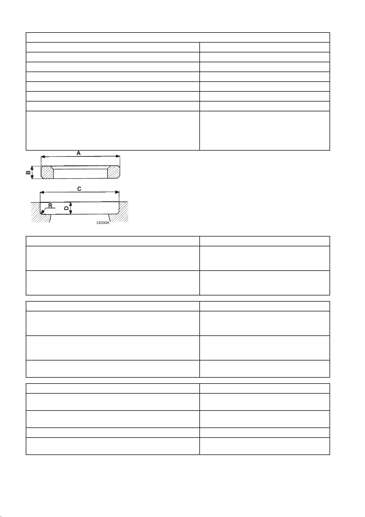
Fig.10 Valve seat and valve seat's position
Valve seats
Outside diameter (A) standard:
Inlet
Exhaust
Ø45 (+0.065+0.081) mm (1.78 in)
Ø43 (+0.07+0.086) mm (1.70 in)
Height (B):
Inlet
Exhaust
7.1 ±0.04 mm (0.279 ±0.0016 in)
7.25 ±0.025 mm (0.285 ±0.001 in)
Valve seat position
Diameter (C) standard:
Inlet
Exhaust
Ø45 H7 (0/+0.025) mm (1.77 in)
Ø43 H7 (0/+0.025) mm (1.69 in)
Depth (D):
Inlet
Exhaust
11.8 ±0.13 mm (0.46 ±0.005 in)
11.2 ±0.13 mm (0.44 ±0.005 in)
Seat's bottom radius (R):
Inlet/exhaust max. 0.8 mm (0.031 in)
Valve guides
Diameter:
Inlet/exhaust Ø8 0/+0.015 mm (0.31 in)
Height above cylinder head's spring face:
Inlet/exhaust 24.5 ±0.2 mm (0.96 ±0.008 in)
Wear value
Clearance, valve stem - guide
Inlet/exhaust max. 0.7 mm (0.028 in)
15
Valve spring
10 1 15 1612 1113
14
6 2 38 79 4
5
19
20
18
17
V1083869
V1063169
16 15 14 13 17 6 71 8
12 11 10 9 18 3 42 5
Inlet
Length, unloaded 73.8 mm (2.90 in)
Exhaust
Outer valve spring:
Length, unloaded 73.8 mm (2.90 in)
Valve mechanism, tightening torques
Tightening torques
Lock nut, inlet valves 38 ± 4 Nm (28 ± 2.9 lbf ft)
Lock nut, floating valve bridge (exhaust) 38 ± 4 Nm (28 ± 2.9 lbf ft)
Lock nut, brake rocker arm 38 ± 4 Nm (28 ± 2.9 lbf ft)
Spring plate (tab) 25±3 Nm (18.5± 2.2 lbf ft)
Tightening torques, valve cover
Fig.11 Figure 1 Tightening diagram, valve cover
Valve cover
Valve cover, screws 25 ± 3 Nm (18 ± 2 lbf ft)
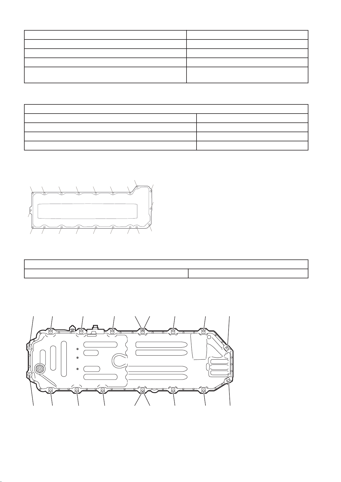
Oil sump, tightening torque
Oil sump, tightening diagram
Fig.12 The illustration shows the oil sump for engine D13H, there may be some differences.
16
Oil sump
V1089423
NOTE!
Tighten the bolts in the numerical order shown in the
figure.
Drain plug, oil sump 52±8 Nm (38±6 lbf ft)
24±4 Nm (18±3 lbf ft)
Oil cooler, tightening torques
Oil cooler
Oil cooler, attaching bolts Nm lbf ft
Tighten the bolts crosswise 27 ±4 19,9 ±2,95
Oil cooler, cover
Fig.13
Oil cooler, cover: Nm lbf ft
Install the cover on the engine block and fit bolt A in the oval hole
Press the cover against the coolant pump housing with the special tool
and install bolt B
Install bolts C and D and tighten them 24 ±4 17.7 ±2.95
Tighten the cover's bolts in order, according to diagram 24 ±4 17.7 ±2.95
Finish by tightening bolts C and D again 24 ±4 17.7 ±2.95
17
Cylinder block, tightening torques
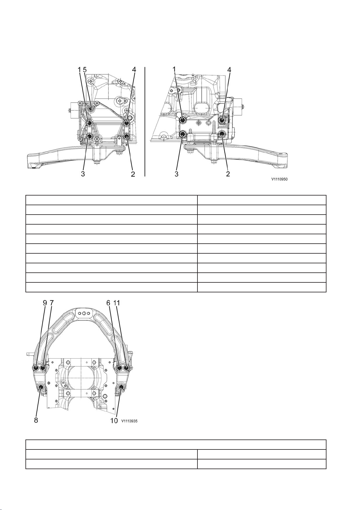
Engine mount incl. bracket
Fig.14 Front engine mount bracket
Front engine mount bracket, cylinder block:
Step 1: Tighten bolt 1. 80 ±15 Nm (59 ±11 lbf ft)
Step 2: Tighten bolts 2 — 4. 105±15 Nm (77.4±11 lbf ft)
Step 3: Angle-tighten bolts 2 — 4 in numerical order 60 ±5°
Step 4: Tighten bolt 1 105±15 Nm (77.4±11 lbf ft)
Step 5: Angle-tighten bolt 1 60 ±5°
Step 6: Tighten bolt 5 Standard bolt tightening torque
Front engine mount to frame 140±25 Nm (103.3±18.4 lbf ft)
Rear engine mount, flywheel housing:
EXC 262±26 Nm (193.2±19 lbf ft)
Fig.15 Front engine mount
Front engine mount to engine mount bracket
Step 1: Tighten bolts 6 – 11 5 ±2 Nm (3.7 ±1.5 lbf ft)
Step 1: Tighten bolts 6 – 11 275 ±45 Nm (203 ±33 lbf ft)
18
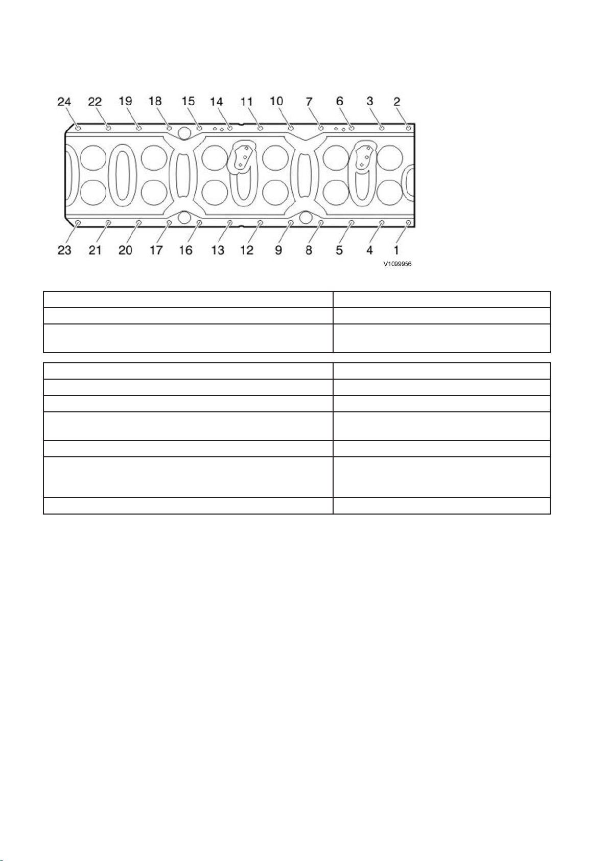
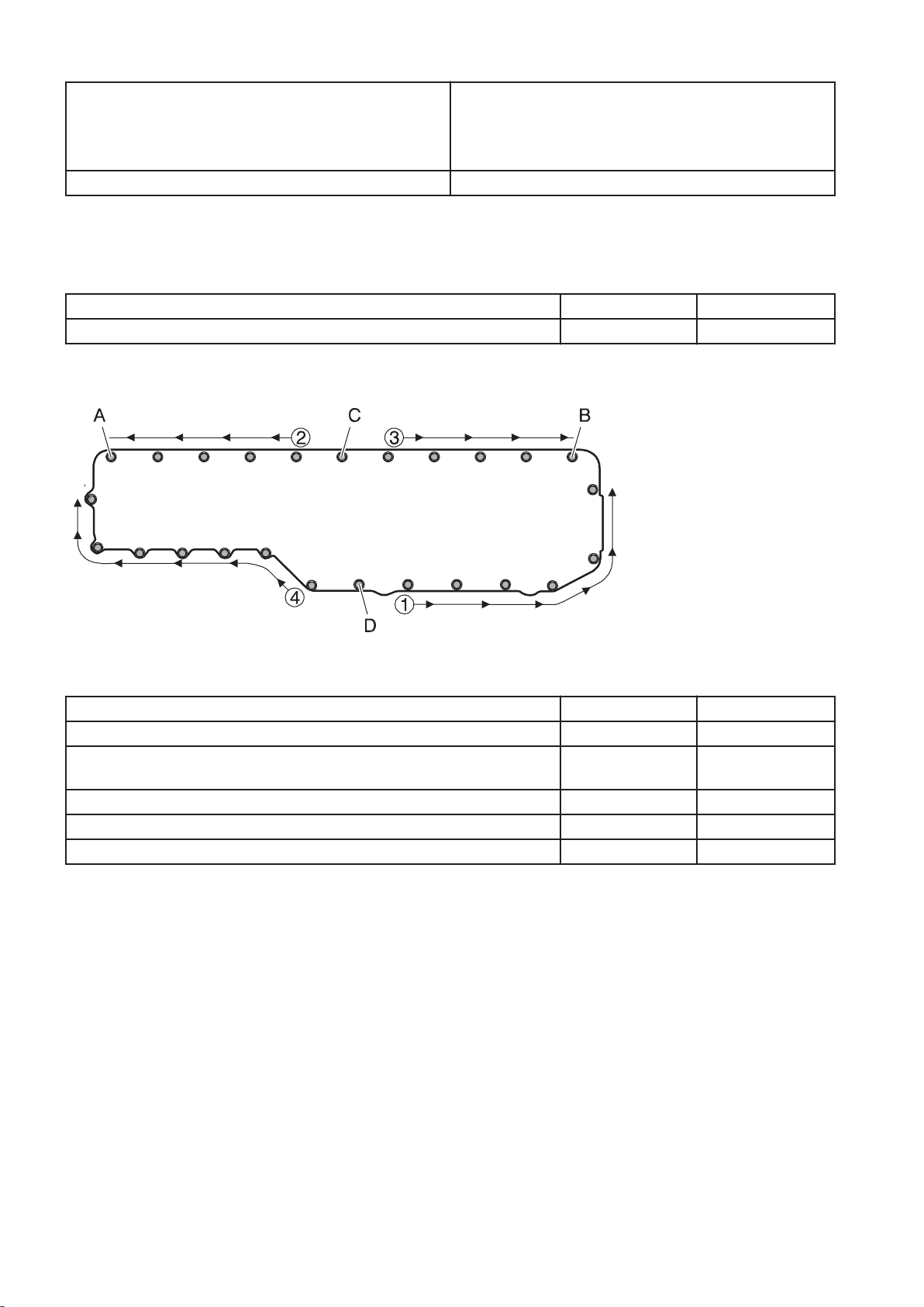
Ladder frame
Fig.16 Ladder frame
Ladder frame
Step 1: Tighten bolts 1 — 24 in numerical order 45±5 Nm (33.19±3.69 lbf ft)
Step 2: Tighten bolts in numerical order 1 — 24 (angletightening)
60 ±5°
Timing gear plate:
M8-bolts 28±4 Nm (20.7±2.95 lbf ft)
Main bearing caps:
Step 1
Step 2 (angle-tightening)
Connecting rod (big-end) caps:
Step 1
Step 2
Step 3 (angle-tightening)
Press tool for measuring liner height 40 Nm (29.5 ft lbf)
150±20 Nm (110.6±14.8 lbf ft)
120 ±5°
20±3 Nm (14.8±2.2 lbf ft)
60±3 Nm (44.3±2.2 lbf ft)
90 ±5°
Inlet
NOTE!
Tighten the bolts according to the numerical order in the figure.
The bolts shall not be reused.
19
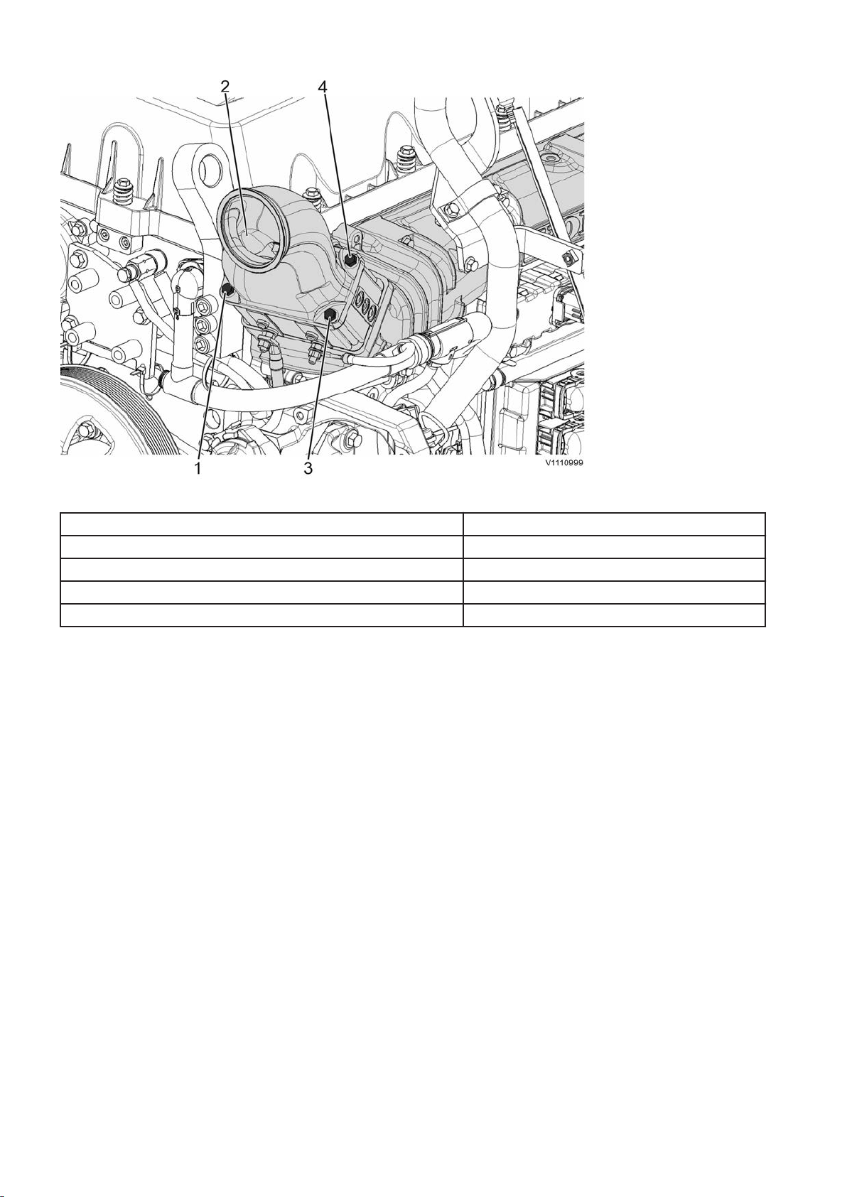
Fig.17 WLO, EXC: Mixing chamber, preheater
Inlet pipe
Mixing chamber, preheater:
Step 1 10±2 Nm (7.38±1.48 lbf ft)
Step 2 24±3 Nm (17.7±2.21 lbf ft)
Plug, M10 (inlet pipe) 20±3 Nm (14.8±2.2 lbf ft)
NOTE!
Torque-tighten the bolts diagonally as shown in the figure.
20
Tightening torque, fuel system
1
3 5 7 9
11
12
108
2
4
6
V1100866
Bolt, fastener yoke, unit injectors. Copper sleeve Steel sleeve
step 1 25 +5/-0 Nm (18.4 +3.7/-0 lbf ft) 20 Nm +5/-0 (14.8 +3.7/-0 lbf ft)
step 2 90° ±5° 90° ±5°
New sleeve or new cylinder head
Bolt, fastener yoke, unit injectors Copper sleeve Steel sleeve
step 1 30 +5/-0 Nm (22 +3.7/-0 lbf ft) 20 +5/-0 Nm (14.8 +3.7/-0 lbf ft)
step 2 150° ±5° 180° ±5°
Step 3: Loose the yoke's bolt until the torqueis10–15 Nm (7.4–11 lbf ft) 10–15 Nm (7.4–11 lbf ft)
step 4 25 +5/-0 Nm (18.4 +3.7/-0 lbf ft) 20 +5/-0 Nm (14.8 +3.7/-0 lbf ft)
step 5 90° ±5° 90° ±5°
Lock nut for adjusting screw, unit injectors 52 ±4 Nm (38.4 ±lbf ft)
Banjo screw, fuel hose
M10 18 ±3 Nm (13.3 ±2.2 lbf ft)
M12 26 ±4 Nm (19.2 ±2.9 lbf ft)
M14 38 ±6 Nm (28 ±4.4 lbf ft)
M16 48 ±8 Nm (35.4 ±6 lbf ft)
Fuel pump (mounted on oil pump) 8 +2/–0 Nm (5.9 +1.5/-0 lbf ft)
Oil pump 24 ±2 Nm (17.7 ±1.5 lbf ft)
Unit injectors, preload Tighten the adjusting screw to zero clearance against the camshaft,
then turn it 240° ±20°
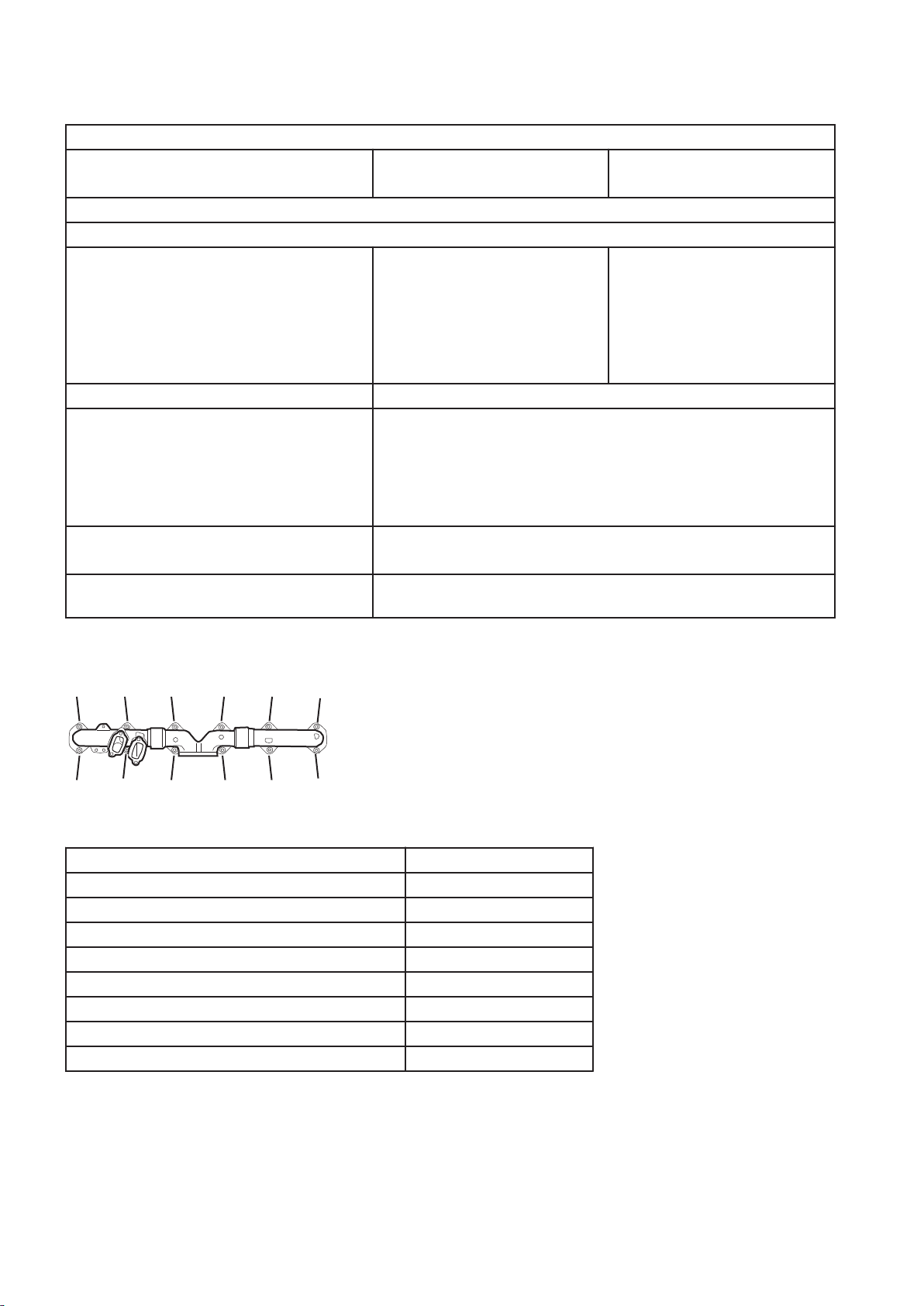
Exhaust manifold, tightening torques
Fig.18
Step 1:
Tighten bolts 1, 4, and 5, 8, and 9, 12 to contact 10±1.5 Nm (7.4±1.1 lbf ft)
Step 2:
Tighten bolts 3 and 2 48±8 Nm (35.4±5.9 lbf ft)
Tighten bolts 7 and 6 48±8 Nm (35.4±5.9 lbf ft)
Tighten bolts 11 and 10 48±8 Nm (35.4±5.9 lbf ft)
Tighten bolts 1 and 4 48±8 Nm (35.4±5.9 lbf ft)
Tighten bolts 5 and 8 48±8 Nm (35.4±5.9 lbf ft)
Tighten bolts 9 and 12. 48±8 Nm (35.4±5.9 lbf ft)
Turbocharger, tightening torques
21
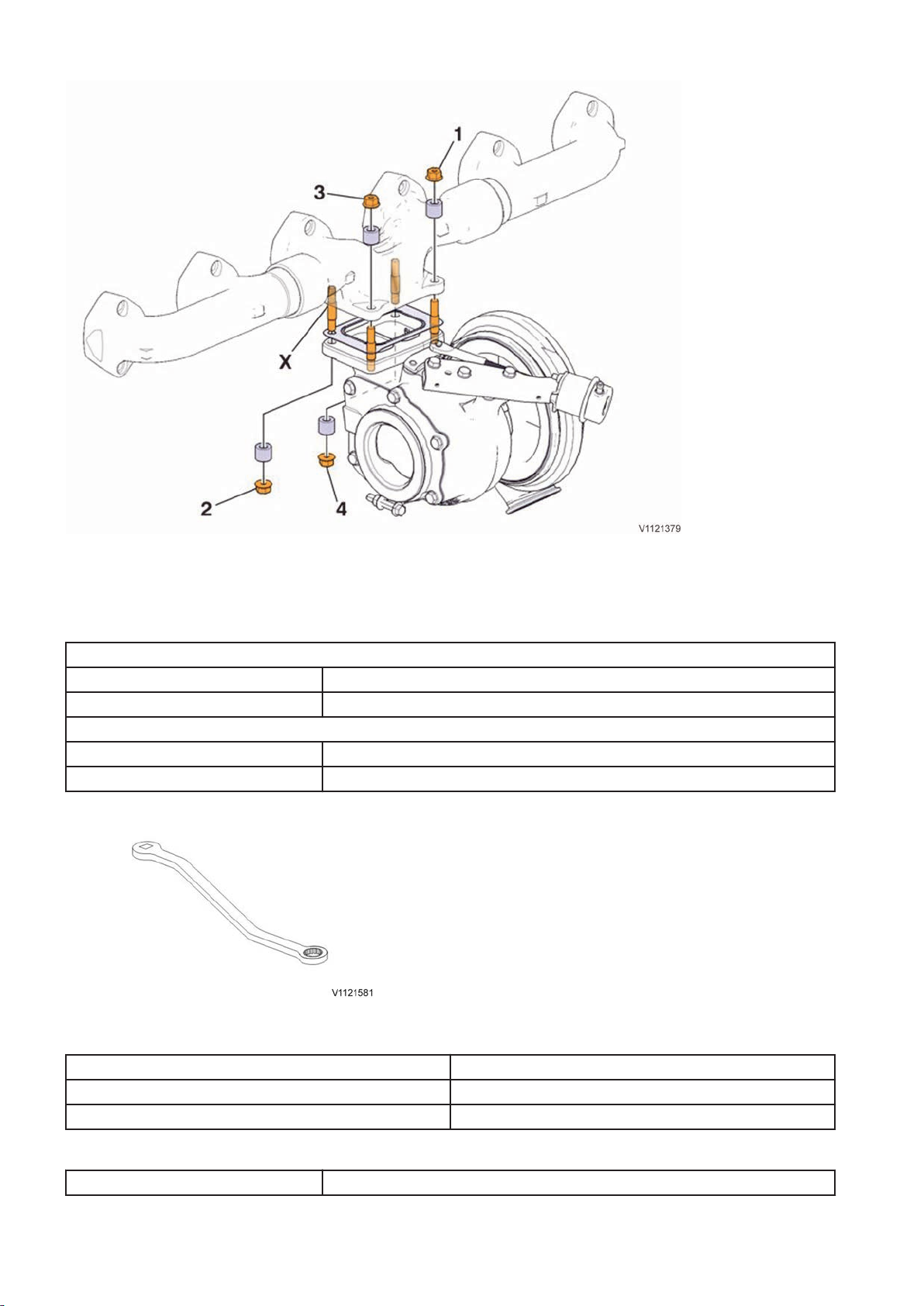
Fig.19 Bolts for installing the turbocharger to the exhaust manifold.
NOTE!
Torque-tighten bolts diagonally as shown in the figure.
Table. Against exhaust manifold
Position 1 and 3
step 1 20 ±4 Nm (14.8 ±3 lbf ft)
step 2 48 ±8 Nm (35.4 ±6 lbf ft)
Position 2 and 4 — using the tool 88830179 Wrench
step 1 16,8 Nm (12.2 lbf ft)
step 2 40,2 Nm (29.6 lbf ft)
Fig.20 88830179 Wrench, for position 2 and 4
Table. Connections for coolant and lubrication oil
Tightening torques, turbo
Coolant lines 38±6 Nm (28±4.4 lbf ft)
Oil lines 48±5 Nm (35.5±3.7 lbf ft)
Table. Charge-air cooler pipe
Clamps 8,5±0,8 Nm (6.3±0.6 lbf ft)
22
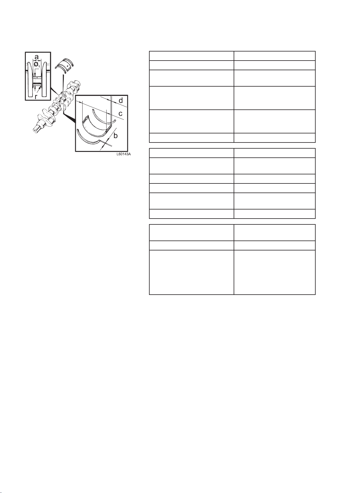
Fig.21
Crank mechanism, specifications
Crankshaft
Length 1 153.8 mm (45.4 in)
Crankshaft, max. axial
clearance
Max. permitted ovality of main
bearing and big-end bearing
pins
Max. permitted conicity of main
bearing and big-end bearing
pins
Max. run-out of middle bearing 0.15 mm (0.0059 in)
Main bearing pin
Diameter (Ø) for reworking,
standard
surface finish, main bearing pin Ra 0.25 mm (0.00098 in)
surface finish, radius Ra 0.4 mm (0.00044 in)
Width, thrust bearing pin (a),
standard
Fillet radius (r) 4.0 mm (0.157 in)
0.4 mm (0.016 in)
0.006 mm (0.00024 in)
< 0.02 mm (< 0.0008 in)
108.0 mm (4.25 in)
47.0 mm (1.85 in)
Thrust washers (thrust
bearings)
Width (b), standard 3.18 mm (0.125 in)
Oversize:
0.1 mm (0.0039 in) 3.28 mm (0.129 in)
0.2 mm (0.0079 in) 3.38 mm (0.133 in)
0.3 mm (0.0118 in) 3.48 mm (0.137 in)
0.4 mm (0.0157 in) 3.58 mm (0.141 in)
23
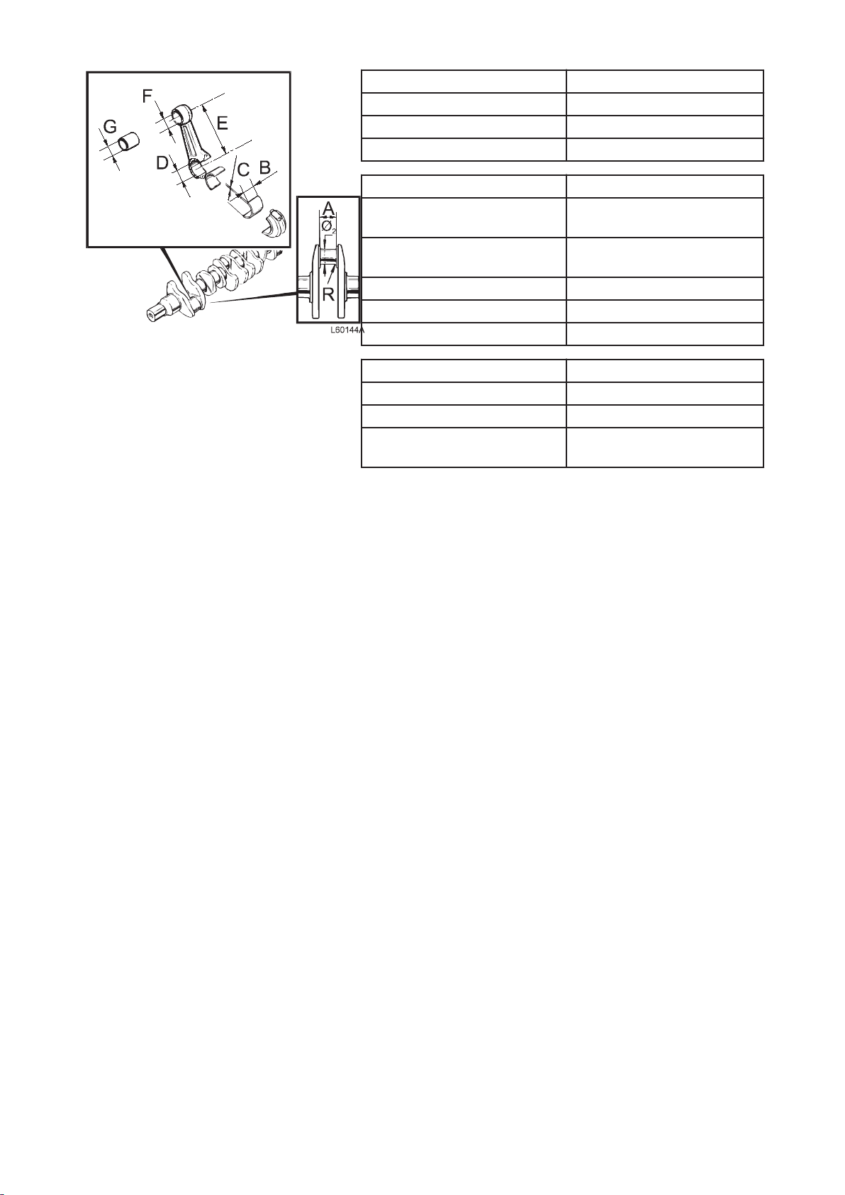
Fig.22
Main bearing shells
Type Replaceable
Outer diameter (c) 113.065 mm (4.451 in)
Thickness (d), standard 2.485 mm (0.098 in)
Crankshaft bearing pins
Diameter (Ø) for reworking,
99 mm (3.897 in)
standard
Surface finish, crankshaft
Ra 0.25
bearing pin
Surface finish, radius Ra 0.4
Width (A) 57 mm (2.244 in)
Fillet radius (r) 4.0 mm (0.157 in)
Connecting rods' bearing shells
Outer diameter (B) 103.85 mm (4.088 in)
Thickness (C), standard 2.389 mm (0.094 in)
Diameter, bearing shell's
103.835 mm (4.088 in)
bearing seat (D)
24
Connecting rod
Length, centre – centre (E) 267.5 mm (10.53 in)
Marking:
"FRONT" on
to face the front.
Connecting rods and caps are
pair-marked with a three-digit
running number.
Connecting rod bushing's
internal diameter (G)
Axial clearance, connecting rod
– crankshaft, with marking
directly opposite each other
Big-end bearing, radial
clearance, oiled part
Straightness (max.) deviation
per 100 mm measured length
Twisting (max.) deviation per
100 mm measured length
Piston
Height above cylinder block
face
Number of ring grooves 3
Front marking Arrow facing forward
rod shall be turned
58 mm (2.283 in)
< 0.35 mm (<0.014 in)
< 0.10 mm (0.0039 in)
0.06 mm (0.0024 in)
0.15 mm (0.0059 in)
0.15–0.21 mm (0.006– 0.008
in)
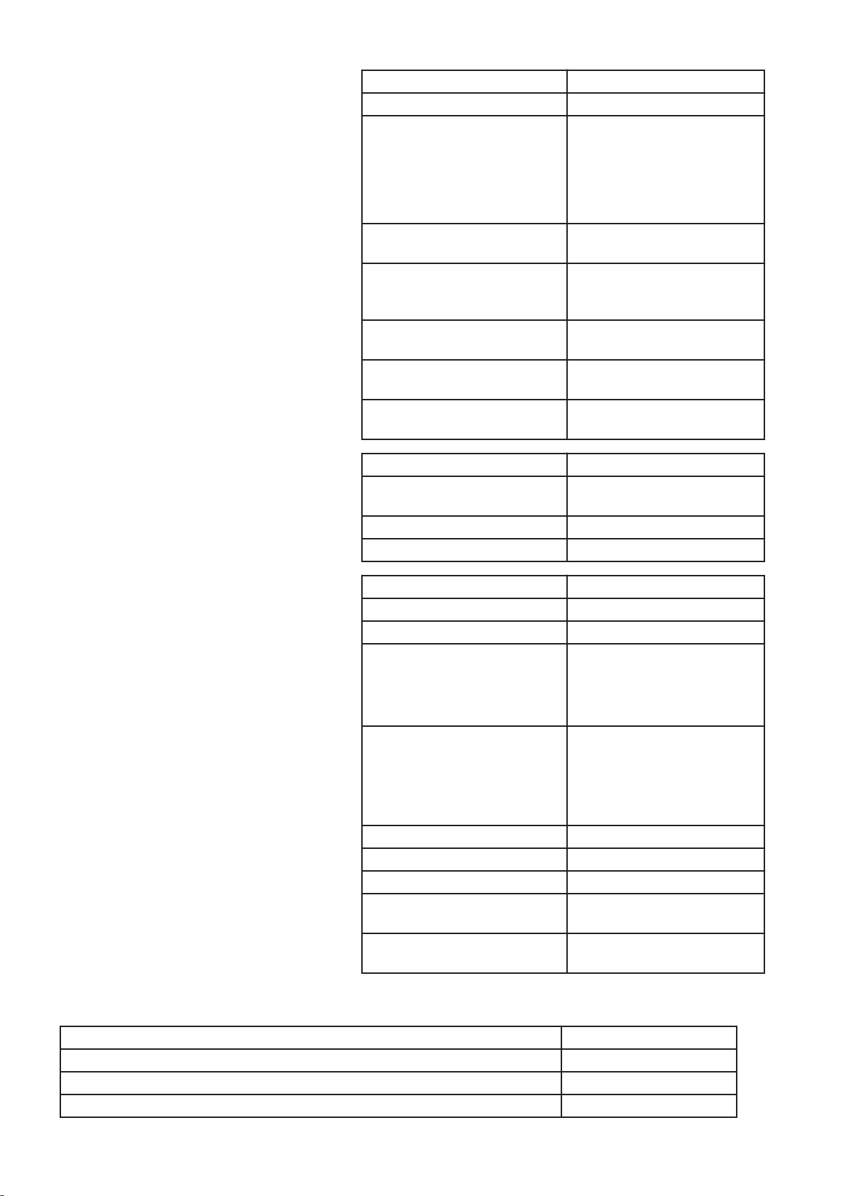
Piston rings
Compression rings
Quantity 2
Piston ring clearance in groove:
upper compression ring Trapezius-shaped profile
lower compression ring 0.09–0.14 mm (0.003– 0.005
in)
Piston ring gap in ring opening:
upper compression ring 0.40–0.55 mm (0.0157–
0.0216 in)
lower compression ring 1.30–1.50 mm (0.051– 0.059
in)
Oil scraper ring
Quantity 1
Width incl. spring 3.41 mm (0.134 in)
Piston ring clearance in groove 0.05–0.10 mm (0.019– 0.039
in)
Piston ring gap in ring opening 0.30–0.55 mm (0.011– 0.021
in)
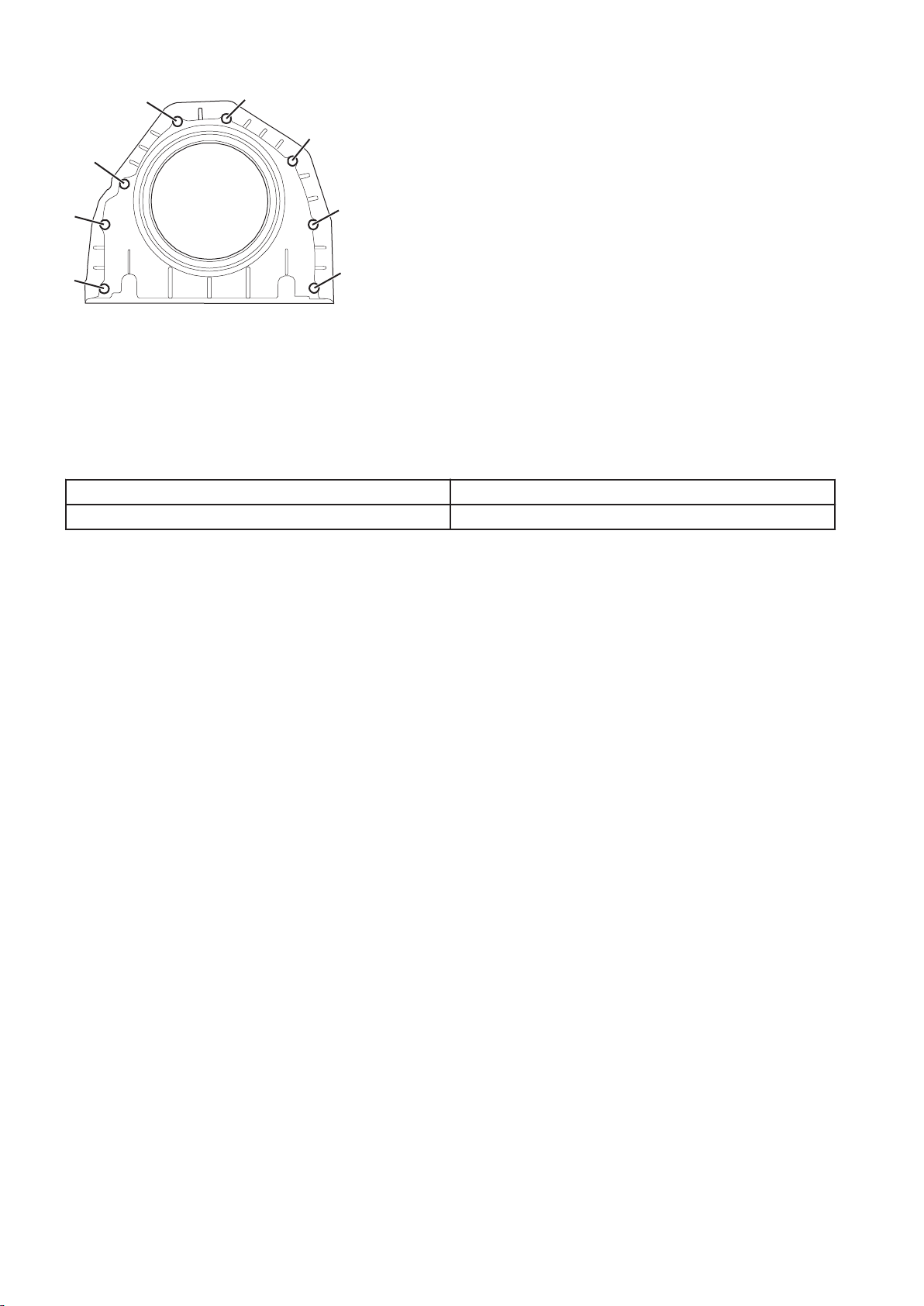
Crankshaft, tightening torques
Cover, crankshaft seal
Step 1: Fasten the cover with the bolts 2 and 7 and tighten to contact.
Step 2: Tighten bolts 2 and 7 24±4 Nm (17.7±2.95 lbf ft)
Step 3: Tighten the bolts in numerical order 1, 3 — 6, 8 as shown in the figure. 24±4 Nm (17.7±2.95 lbf ft)
25
V1048013
1
2
3
4
5
6
7
8
Fig.23
Flywheel, tightening torques
NOTE!
The bolts
Tighten the bolts in the order shown in the following figure. All
bolts are tightened in two steps:
Step 1 60±5 Nm (44±3.7 lbf ft)
Step 2, angle-tightening 120°±10°
may only be reused twice, then new bolts shall be used.
26

Fig.24 Flywheel
Belt pulley/vibration damper, tightening torques
Fig.25 Belt pullet/vibration damper
Vibration damper and belt pulley
Step 1, according to numerical order in figure: 35±5 Nm (25.8±3.7 lbf ft)
Step 2, according to numerical order in figure: 90±10 Nm (66.4±7.4 lbf ft)
27

ENGINE WITH MOUNTING AND EQUIPMENT
21 ENGINE
210 General, common info about 211 218
Engine, mounting in work stand
Op. no. 210-081
Tools:
9986485 Support
88800345 Fixture
88800123 Fixture
Lifting eye, 2 pcs.
Sling 3 m (118 in)
Ratchet block 1,500 kg (3307 lbs)
NOTE!
Since the engine illustrations in the service publications are
reused for different engine versions, some parts may vary from
the version
illustrations is always correct.
in question. However, the essential information in the
Engine D13F, weight:
WLO approx. 1,330 kg (3,932 lbs)
EXC approx. 1,330 kg (3,932 lbs)
1 Unplug the sensors and the cable harness. Unplug the
connectors from the E-ECU. Remove the cable channel.
28
V1044013
1
2
3
4
5
6
7
8
10
11
9
Fig.26 Sensor, control system
1 Sensor for coolant level, SE2603
Sensor for coolant temperature, SE2606
2
3 E-ECU
4 Cable channel
5 Camshaft sensor, engine position, SE2703
6 Sensor for boost pressure/charge-air temperature, SE2507/SE2508
7 Sensor for air pressure/air temperature, SE2501/SE2502
8 Speed (rpm) sensor, flywheel, SE2701
9 Sensor for oil pressure, SE2203
10 Sensor for oil level/oil temperature, SE2205/SE2202
11 Sensor for crankcase pressure, SE2509
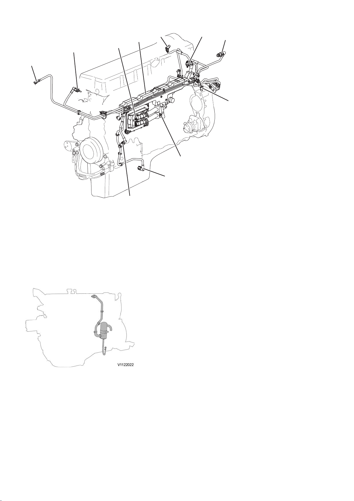
2 Disconnect the oil trap hose from the oil sump. Disconnect
the oil trap pipe from the valve cover. Remove the oil trap,
pipe and hose.
Fig.27 Oil trap with hose and pipe
NOTE!
Collet the waste oil in a suitable container.
29
Loading...