


Volvo Trucks North America
Greensboro, NC USA
Service Bulletin
Trucks
Date |
Group |
No. |
Page |
1.2007 |
230 |
254 |
1(12) |
Fuel System
Design and Function
D13F
Fuel System, Design and Function
W2005843
This information covers the design and function of the fuel system on the Volvo D13F engine.
Contents
•“Fuel System” page 2
Note: Information is subject to change without notice.
Illustrations are used for reference only and can differ slightly from the actual vehicle being serviced. However, key components addressed in this information are represented as accurately as possible.
PV776-20177414 |
USA23087.ihval |
Volvo Trucks North America |
Date |
Group |
No. |
Page |
Service Bulletin |
1.2007 |
230 |
254 |
2(12) |
Design and Function
Fuel System
When fault tracing, it is important to understand the function of the system in order to avoid replacing non-defective components.
System Function
W2005892
Volvo Trucks North America |
Date |
Group |
No. |
Page |
Service Bulletin |
1.2007 |
230 |
254 |
3(12) |
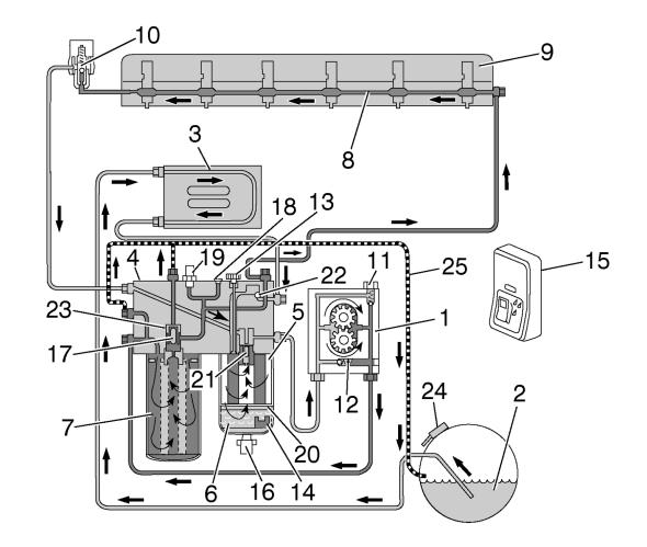
Fuel is drawn up the fuel lines by the supply pump (1) through the pickup tube in the fuel tank (2) in through the Engine Electronic Control Unit (EECU) cooling coil (3), and into the fuel filter housing (4). The fuel filter housing is equipped with a pre-filter (5) and a water separator (6), where fuel is filtered through the primary filter that separates any water from the fuel.
The supply pump (1) forces the fuel into the fuel filter housing through the main filter (7) to a cylinder head longitudinal fuel gallery (8). This channel supplies each unit injector (9) with pressurized fuel by a circular groove around each unit injector in the cylinder head. The overflow valve (10) controls the fuel supply pressure to the unit injectors.
The return fuel from the overflow valve (10) is returned back to the fuel filter housing and is mixed with the fuel from the fuel tank in a channel within the fuel filter housing
(4).
Supply Pump Valves
Two valves are located in the supply pump (1).
The safety valve (11) allows fuel to flow back to the suction side when the pressure becomes too high, e.g., if the fuel filter is blocked or is too restricted. The non-return valve (12) opens when hand-priming is used.
Automatic Bleeding
If air gets into the system, it is bled when the engine starts. During bleeding, the air is pressed out through the fuel filter housing over to the fuel tank through the return line (25). Bleeding for the filter replacement is controlled by valves (17) and (23).
Water Drainage
Draining water from the water separator (5) requires the following:
•The sensor (14) in the water separator indicates water in the fuel bowl.
•The engine is not running.
•The ignition key is in the ON position.
•The parking brake is applied.
When the switch (15) is depressed (located in the cab instrument panel), the drain valve (16) opens for about 15 seconds and drains the water. If additional drainage is needed, wait 6 minutes before repeating because the function is on a timer.
Manual Hand Pump
The manual hand pump (11) is located on the fuel filter housing and is used to pump fuel (when the engine is not running) after the fuel system has been drained for repair, etc. The non-return valve (22) for the hand-priming pump is also located in the fuel filter housing.
Volvo Trucks North America |
Date |
Group |
No. |
Page |
Service Bulletin |
1.2007 |
230 |
254 |
4(12) |
Other
The fuel filter housing eliminates the need to drain the fuel when replacing the filter. The valve pegs (17) and (21) close when the fuel filter is removed. It is not necessary to bleed the fuel system after replacing the filter, since this is performed automatically when the engine is started and runs for more than 2 minutes.
The plugged outlet (18) is fitted on the fuel filter housing. The outlet is used when measuring supply pressure after the fuel filter with an external pressure gauge. The pressure sensor (19) on the fuel filter housing monitors the supply pressure after the fuel filter. A fault code is displayed on the instrument cluster if the fuel supply pressure is less than the specified value.
A fuel heater (20) is available as an option. It is located in the lower part of the water separator. The fuel tank breather (24) prevents excessive vacuum in the fuel tank(s) which could possibly result in fuel starvation.
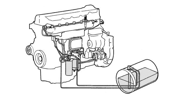
Fuel System Components
W2004976
 Loading...