


Toshiba RAS-M10GDCV-E, RAS-M16GDCV-E, RAS-M16GDV-E, RAS-M10GDV-E, RAS-M13GDCV-E INSTALLATION MANUAL
...INSTALLATION MANUAL
MANUEL D’INSTALLATION
INSTALLATIONS-HANDBUCH
MANUALE DI INSTALLAZIONE MANUAL DE INSTALACIÓN MANUAL DE INSTALAÇÃO
ЕГЧЕЙСЙДЙПЕГКБФБУФБУЗУ
AIR CONDITIONER (MULTI-SPLIT TYPE) CLIMATISEUR (TYPE MULTI-SPLIT) KLIMAGERÄT (MULTI-SPLIT SYSTEM)
CONDIZIONATORE D'ARIA (TIPO MULTIAMBIENTI) AIRE ACONDICIONADO (TIPO MULTI-SPLIT)
CONDICIONADOR DE AR (TIPO COM MÚLTIPLA DIVISÃO)
КЛЙМБФЙУФЙКП (TÕÐÏÓ MULTI-SPLIT)
<Concealed Duct Type>
<Type à conduits dissimulés> / <Luftkanal verborgen montiert> <Tipo a condotto nascosto> / <Modelo con conductos ocultos> <Tipo com Conduto Embutido> / <Фэрпт ухгкекблхммЭнпх бгщгпэ>
Indoor Unit |
Outdoor Unit |
Unité intérieure/Raumeinheit |
Unité extérieure/Außeneinheit |
Unità interna/Unidad interior |
Unità esterna/Unidad exterior |
Unidade Interna/ЕущфесйкЮ МпнЬдб |
Unidade Externa/ЕощфесйкЮ МпнЬдб |
Cooling Only Model
Modèle à froid seul/Geräte nur zur Kühlung
Modello solo per raffreddamento/Modelo de refrigeración únicamente
Modelo Apenas para Refrigeração/МпнфЭлп Шэозт брпклейуфйкЬ
RAS-M10GDCV-E RAS-M13GDCV-E RAS-M16GDCV-E
RAS-M14GACV-E RAS-M18GACV-E RAS-3M23GACV-E RAS-4M27GACV-E
Heat Pump Model
Modèle à thermopompe/Geräte mit Heizung
Modello con pompa di riscaldamento/Modelo con bomba de calor Modelo da Bomba de Calor/МпнфЭлп ме БнфлЯб Иесмьфзфбт
RAS-M10GDV-E RAS-M13GDV-E RAS-M16GDV-E
RAS-M14GAV-E RAS-M18GAV-E RAS-3M26GAV-E RAS-4M27GAV-E
Please read this Installation Manual carefully before installing the Air Conditioner. Veuillez lire attentivement ce Manuel d’installation avant d’installer le climatiseur.
Bitte lesen Sie dieses Handbuch sorgfältig, bevor Sie mit der Installation des Klimagerätes beginnen.
Prima di installare il condizionatore d'aria, leggere attentamente questo Manuale di installazione.
Lea atentamente este Manual de instalación antes de proceder a la instalación del aparato de aire acondicionado.
Por favor, leia este Manual de Instalação atentamente, antes da instalação do Condicionador de Ar.
Рбсбкблю дйбвЬуфе рспуечфйкЬ фп ЕгчейсЯдйп ЕгкбфЬуфбузт рсйн брь фзн егкбфЬуфбуз фпх Клймбфйуфйкпэ.
•This Manual describes the installation method of the indoor unit.
•For installation of the outdoor unit, follow to the Installation Manual attached to the outdoor unit.
•The supply and return air panels are to be procured locally.
•Ce manuel décrit la procédure d’installation de l’unité intérieure.
•Pour installer l’unité extérieure, reportez-vous au Manuel d’installation fourni avec l’unité extérieure.
•Les panneaux d’alimentation en air et de retour de l’air doivent être fournis sur place.
•In diesem Handbuch wird die Installation der Raumeinheit beschrieben.
•Um die Außeneinheit zu installieren, folgen Sie den Anweisungen in dem Handbuch, das der Außeneinheit beiliegt.
•Die Zuund Abluftgitter müssen bauseits bereit gestellt werden.
•Questo manuale illustra il metodo di installazione per l'unità interna.
•Per l'installazione dell'unità esterna, seguire le istruzioni del Manuale di installazione in dotazione con l'unità esterna.
•I pannelli di alimentazione e per l'aria di ritorno devono essere procurati dal cliente.
•Este manual describe el método de instalación de la unidad interior.
•Para la instalación de la unidad exterior, consulte el Manual de instalación que acompaña a la unidad exterior.
•Los paneles de aire de suministro y de retorno deberán adquirirse localmente.
•Este manual descreve o método de instalação da unidade interna.
•Para a instalação da unidade externa, siga o Manual de Instalação, entregue juntamente com a unidade externa.
•Os painéis do ar de alimentação e de retorno poderão ser obtidos no local.
•Фп рбсьн ЕгчейсЯдйп ресйгсЬцей фз мЭипдп егкбфЬуфбузт фзт еущфесйкЮт мпнЬдбт.
•Гйб фзн егкбфЬуфбуз фзт еощфесйкЮт мпнЬдбт, бкплпхиЮуфе фп ЕгчейсЯдйп ЕгкбфЬуфбузт рпх рспмзиеэефбй ме фзн еощфесйкЮ мпнЬдб.
•Фб кбрЬкйб рбспчЮт кбй ербнбцпсЬт фпх бЭсб рспмзиеэпнфбй брь фзн фпрйкЮ бгпсЬ.

|
CONTENTS |
|
|
||||
1 |
PRECAUTIONS FOR SAFETY .................................... |
2 |
6 |
REFRIGERANT PIPING ............................................ |
13 |
ENGLISH |
|
2 |
SELECTION OF INSTALLATION PLACE ................... |
4 |
7 |
EVACUATING ............................................................. |
14 |
||
3 |
INSTALLATION OF INDOOR UNIT ............................. |
5 |
8 |
ELECTRICAL WORK ................................................ |
15 |
||
4 |
AIR DUCTING WORK |
8 |
9 |
INSTALLATION/SERVICING TOOLS |
17 |
||
|
|||||||
5 |
DRAIN PIPING WORK ............................................... |
12 |
|
|
|
|
|
|
|
|
|
|
|
||
|
|
INHALT |
|
|
|
||
1 |
MESURES DE SECURITE ........................................ |
19 |
6 |
TUYAUX DE REFRIGERANT .................................... |
30 |
FRANCAIS |
|
2 |
SELECTION DU LIEU D’INSTALLATION ................. |
21 |
7 |
EVACUATION DE L’AIR ............................................. |
31 |
||
3 |
INSTALLATION DE L’UNITE INTERIEURE .............. |
22 |
8 |
INSTALLATION ELECTRIQUE .................................. |
32 |
||
4 |
INSTALLATION DES CONDUITS D’AIR ................... |
25 |
9 |
OUTILS D’INSTALLATION/D’ENTRETIEN ............... |
34 |
||
5 |
INSTALLATION DES TUYAUX D’EVACUATION ....... |
29 |
|
|
|
|
|
|
|
INDICE |
|
|
|
||
1 |
SICHERHEITSVORKEHRUNGEN ............................ |
36 |
6 |
KühLMITTEL-LEITUNGEN ....................................... |
47 |
DEUTSCH |
|
2 |
AUSWAHL DES AUFSTELLUNGSORTES ............... |
38 |
7 |
ENTLÜFTEN DER ROHRLEITUNGEN ..................... |
48 |
||
3 |
INSTALLATION DER RAUMEINHEIT ....................... |
39 |
8 |
ELEKTROINSTALLATION ......................................... |
49 |
||
4 |
VERLEGEN DER LüfTUNGSKANälE |
42 |
9 |
INSTALLATIONS/WARTUNGSWERKZEUGE |
51 |
||
|
|||||||
5 |
INSTALLATION DES KONDENSWASSER-ABLAUFS .. |
46 |
|
|
|
|
|
|
|
|
|
|
|
||
|
|
INDICE |
|
|
|
||
1 |
PRECAUZIONI PER LA SICUREZZA ....................... |
53 |
6 |
TUBAZIONE DEL REFRIGERANTE ......................... |
64 |
ITALIANO |
|
2 |
SELEZIONE DEL LUOGO DI INSTALLAZIONE ....... |
55 |
7 |
SPURGO .................................................................... |
65 |
||
3 |
INSTALLAZIONE DELL'UNITÀ INTERNA ................ |
56 |
8 |
LAVORO ELETTRICO ............................................... |
66 |
||
4 |
LAVORO PER IL CONDOTTO DELL'ARIA |
59 |
9 |
ATTREZZI PER L'INSTALLAZIONE/PER LA |
|
||
|
|
||||||
5 |
LAVORO PER LA TUBAZIONE DI SCARICO |
63 |
|
MANUTENZIONE ...................................................... |
68 |
|
|
|
|
|
|
||||
|
|
|
|
||||
|
CONTENIDO |
|
|
||||
1 |
PRECAUCIONES DE SEGURIDAD .......................... |
70 |
6 |
TUBO DE REFRIGERANTE ...................................... |
81 |
ESPAÑOL |
|
2 |
SELECCIÓN DEL LUGAR DE INSTALACIÓN ......... |
72 |
7 |
EVACUACIÓN ............................................................ |
82 |
||
3 |
INSTALACIÓN DE LA UNIDAD INTERIOR .............. |
73 |
8 |
TRABAJOS EN EL SISTEMA ELÉCTRICO ............. |
83 |
||
4 |
TRABAJOS DE CANALIZACIÓN DEL AIRE |
76 |
9 |
HERRAMIENTAS DE INSTALACIÓN/REPARACIÓN 85 |
|||
|
|||||||
5 |
TRABAJOS DE CANALIZACIÓN DE DESAGÜE ..... |
80 |
|
|
|
|
|
|
|
|
|
|
|
||
|
|
ÍNDICE |
|
|
PORTUGUÊS |
||
1 |
PRECAUÇÕES DE SEGURANÇA ............................ |
87 |
6 |
TUBULAÇÃO DO REFRIGERANTE ......................... |
98 |
||
2 |
SELEÇÃO DO LOCAL DE INSTALAÇÃO ................ |
89 |
7 |
EXPURGO ................................................................. |
99 |
||
3 |
INSTALAÇÃO DA UNIDADE INTERNA .................... |
90 |
8 |
SERVIÇO ELÉTRICO .............................................. |
100 |
||
4 |
TRABALHO DE CANALIZAÇÃO DO AR ................. |
93 |
9 |
FERRAMENTAS DE INSTALAÇÃO/REPARO ........ |
102 |
||
5 |
TRABALHO DE CANALIZAÇÃO DOESCOAMENTO97 |
|
|
|
|||
|
|
|
|
||||
|
|
|
|
|
|
|
|
|
РЕСЙЕЧПМЕНБ |
|
|
||||
РСПЦХЛБОЕЙУ БУЦБЛЕЙБУ ................................. |
104 |
$ УЩЛЗНЩУЕЙУ ШХКФЙКПХ ...................................... |
115 |
ЕЛЛЗНЙКБ |
|||
|
ЕРЙЛПГЗ ФПХ ЧЩСПХ ЕГКБФБУФБУЗУ .............. |
106 |
% ЕККЕНЩУЗ ............................................................. |
116 |
|||
! ЕГКБФБУФБУЗ ФЗУ ЕУЩФЕСЙКЗУ МПНБДБУ .... |
107 |
& ЗЛЕКФСПЛПГЙКБ .................................................. |
117 |
||||
" ЕГКБФБУФБУЗ БЕСБГЩГЩН |
110 |
' ЕСГБЛЕЙБ ЕГКБФБУФБУЗУ/ ЕРЙУКЕХЗУ |
119 |
||||
|
|||||||
# ЕГКБФБУФБУЗ УЩЛЗНЩУЕЩН БРПУФСБГГЙУЗУ114 |
|
|
|
|
|||
|
|
|
|
|
|
|
|

Accessory parts and Parts to be procured locally
r Accessory parts
Part name |
Q’ty |
Shape |
Wireless remote
1
controller
Remote controller holder |
1 |
|
|
Mounting screws for |
|
remote controller holder |
2 |
3.5mm (diam.) x 16mm |
|
|
|
Drain hose |
1 |
|
|
Installation Manual |
1 |
r Parts to be procured locally
Connecting pipe (Liquid side)
(6.35mm (diam.), Nominal (diam.) 1/4” thick 0.8mm)
Connecting pipe (Gas side)
(12.7mm (diam.), Nominal (diam.) 1/2” thick 0.8mm) RAS-M16GDCV-E, RAS-M16GDV-E
(9.52mm (diam.), Nominal (diam.) 3/8” thick 0.8mm) RAS-M10GDCV-E, RAS-M10GDV-E RAS-M13GDCV-E, RAS-M13GDV-E
Power supply cord
2.5mm² (H07RN-F or 245IEC66)
Part name |
Q’ty |
Shape |
Elbow thermal-insulating |
1 |
|
cover |
|
|
|
|
|
Batteries |
2 |
|
(Manganese) |
|
|
|
|
|
Black screws |
|
|
for switch panel |
2 |
|
4mm (diam.) x 10mm |
|
|
Tapping screws |
|
|
for flange (2nd type) |
16 |
|
4mm (diam.) x 8mm |
|
|
Owner’s Manual |
1 |
|
Connecting cable |
|
|
H07RN-F or 245IEC66 (1.0mm²) |
|
|
Thermal insulation for refrigerant pipe
(10mm or more, thermal insulating foam polyethylene)
Thermal insulation for drain pipe (10mm or more, foam polyethylene)
Drain pipe (Outer 26mm (diam.))
Tapes
Grounding cable (1.6mm (diam.) or more)
1

1 PRECAUTIONS FOR SAFETY
Power supply cord of Outdoor unit shall be 2.5mm² (H07RN-F or 245 IEC66) polychloroprene sheathed flexible cord.
•Read this “Precautions for Safety” carefully before Installation.
•The precautions described below include the important items regarding safety. Observe them without fail.
•After the installation work, perform a trial operation to check for any problem. Follow the Owner’s Manual to explain to the customer how to use and maintain the unit.
•Turn off the main power supply switch (or breaker) before the unit maintenance.
•Ask the customer to keep the Installation Manual together with the Owner’s Manual.
CAUTION New Refrigerant Air Conditioner Installation
•THIS AIR CONDITIONER ADOPTS THE NEW HFC REFRIGERANT (R410A) WHICH DOES NOT DESTROY OZONE LAYER.
The characteristics of R410A refrigerant is easy to absorb water, oxidizing membrane or oil, and its pressure is approx. 1.6 times of refrigerant R22. Accompanied with adoption of the new refrigerant, refrigerating oil has been also changed. Therefore, during installation work, be sure that water, dust, former refrigerant, or refrigerating oil does not enter into the refrigerating cycle of new refrigerant air conditioner.
To prevent from mixing of refrigerant and refrigerating oil, the sizes of connecting sections of charging port of the main unit or installation tools are different from those for the conventional refrigerant.
Accordingly, the exclusive tools are required for the new refrigerant (R410A).
For connecting pipes, use new and clean piping materials with high pressure-tight force, which were made for R410A only, so that water or dust does not enter. Moreover, do not use the existing piping because there are problems about pressure-tight force and impurity it.
ENGLISH
CAUTION To Disconnect the Appliance from the Main Power Supply.
This appliance must be connected to the main power supply by means of a circuit breaker or a switch with a contact separation of at least 3 mm.
If this is not possible, a power supply plug with grounding must be used. This plug must be easily accessible after installation. The plug must be disconnected from the power supply socket in order to disconnect the appliance completely from the mains.
The installation fuse (25A D type  ) must be used for the power supply line of this conditioner.
 WARNINGS
•Ask an authorized dealer or qualified installation professional to install/maintain the air conditioner.
Inappropriate installation may result in water leakage, electric shock or fire.
•Turn off the main power supply switch or breaker before attempting any electrical work.
Make sure all power switches are off. Failure to do so may cause electric shock.
•Connect the connecting cable correctly.
If the connecting cable is connected by wrong way, electric parts may be damaged.
•When moving the air-conditioner for installing it in another place again, be very careful not to get the specified refrigerant with any other gaseous body into the refrigeration cycle.
If air or any other gas is mixed in the refrigerant, the gas pressure in the refrigeration cycle becomes abnormally high and it resultingly causes burst of the pipe and injuries on persons.
2

1 PRECAUTIONS FOR SAFETY
•Never modify this unit by removing any of the safety guards or by by-passing any of the safety interlock switches.
•Exposure of unit to water or other moisture before installation may cause a short circuit.
Do not store it in a wet basement or expose to rain or water.
•After unpacking the unit, examine it carefully for possible damage.
•Do not install in a place that can increase the vibration of the unit.
•To avoid personal injury, be careful when handling parts with sharp edges.
•Perform installation work properly according to the Installation Manual.
Inappropriate installation may result in water leakage, electric shock or fire.
•When installing the air conditioner in a small room, provide appropriate measures to ensure that the concentration of refrigerant in the room does not exceed the critical level should leakage occur.
It is not dangerous refrigerant; it has not toxicity or combustibility. However, a concentration above 0.3kg/m³ as criterion still causes suffocation. The volume of refrigerant charged to the Multi System air conditioner is more than the volume charged to a conventional individual system.
•Install the air conditioner securely in a location where the weight of the unit can be sustained adequately.
•Perform the specified installation work to guard against an earthquake.
If the air conditioner is not installed appropriately, accidents may occur due to the falling unit.
•If refrigerant gas has leaked during the installation work, ventilate the room immediately.
If the leaked refrigerant gas comes in contact with fire, noxious gas may generate.
•After the installation work, confirm that refrigerant gas does not leak.
If refrigerant gas leaks into the room and flows near a fire source, such as a cooking range, noxious gas may generate.
•The electrical work must be performed by a qualified electrician in accordance with the Installation Manual. Make sure the air conditioner uses an exclusive circuit.
An insufficient circuit capacity or inappropriate installation may cause fire.
•When wiring, use the specified cables and connect the terminals securely to prevent external forces applied to the cable from affecting the terminals.
•Be sure to provide grounding.
Do not connect ground wires to gas pipes, water pipes, lightning rods or ground wires for telephone cables.
•Conform to the regulations of the local electric company when wiring the power supply.
Inappropriate grounding may cause electric shock.
•Do not install the air conditioner in a location subject to a risk of exposure to combustible gas.
Otherwise, the combustible gas leaks, stays around the unit and a fire may occur.
3

2 SELECTION OF INSTALLATION PLACE
 WARNING
•Install the air conditioner where there is sufficient strength to withstand the weight of the unit.
If the strength is not sufficient, the unit may fall down resulting in injury.
•Install the air conditioner at a position keeping the height by 2.5m or more from the floor.
If you insert your hands or others directly into the unit during running of the air conditioner, it is dangerous because you may contact with revolving fan or active electricity.
 CAUTION
•Do not install the air conditioner in a location subject to a risk of exposure to combustible gas.
Otherwise, the combustible gas leaks, stays around the unit and a fire may occur.
Upon approval of the customer, install the air conditioner in a place that satisfies the following conditions.
•Place where the unit can be installed horizontally.
•Place where a sufficient servicing space can be ensured for safe maintenance and check.
•Place where drained water will not cause any problem.
•Make sure that the user cannot access the unit main body after the installation.
Avoid installing in the following places.
•Place exposed to air with high salt content (seaside area), or place exposed to large quantities of sulfide gas (hot spring). (Should the unit be used in these places, special protective measures are needed.)
•Place exposed to oil, vapor, oil smoke or corrosive gas.
•Place where organic solvent is used nearby.
•Place close to a machine generating high frequency.
•Place where the discharged air blows directly into the window of the neighboring house. (For outdoor unit)
•Place where noise of the outdoor unit is easy to transmit.
(When installing the air conditioner on the boundary with the neighbor, pay due attention to the level of noise.)
•Place with poor ventilation. (Before air ducting work, check whether value of air volume, static pressure and duct resistance are correct.)
Installation space
Secure the space required to installation and servicing.
100 or more |
|
|
300 or more |
|||||||||||
|
|
|
|
|
|
|
for service space |
|||||||
|
|
|
|
|
|
|
|
|
|
|
|
|
|
|
|
|
|
|
|
|
|
|
|
|
|
|
|
|
|
|
|
|
|
|
|
|
|
|
|
|
|
|
|
|
|
|
|
|
|
|
|
|
|
|
|
|
|
|
|
|
|
|
|
|
|
|
|
|
|
|
|
|
|
|
|
|
|
|
|
|
|
|
|
|
|
|
|
|
|
|
|
|
|
|
|
|
|
|
|
|
|
|
|
|
|
|
|
|
|
|
|
|
|
|
|
|
|
|
|
240
or more
Selection of installation place
In case of continues the operation of the indoor unit under high-humidity conditions as described below, dew may condense and water may drop.
Especially, high-humidity atmosphere (dew point temperature : 23°C or more) may generate inside of the ceiling.
1.Unit is installed inside of the ceiling with slated roof.
2.Unit is installed at a location using inside of the ceiling as fresh air take-in path.
3.Kitchen
If installing a unit at such place, adhere insulating material (glass wool, etc.) additionally over all the positions of the indoor unit which come to contact with high-humidity atmosphere.
Advice
Set a check port at right side of the unit (size: 450 x 450mm) for piping, maintenance, and servicing.
4

3 INSTALLATION OF INDOOR UNIT
 WARNING
Install the air conditioner certainly at a place to sufficiently withstand the weight. If the strength is insufficient, the unit may fall down resulting in human injury. Perform a specified installation work to guard against an earthquake.
An incomplete installation can cause accidents by the units falling and dropping.
Return air methed is choiced from rear or under direction as shown in figure.
Return air from rear side |
Return air from below side |
•If a system to suck in air directly from the bottom of the unit is adopted, the noise level increases. It is recommended to mount the return duct so that air is not directly sucked in.
Installation procedure
1.Lay drain pipes, refrigerant pipes, and connecting cables under wall or ceiling concurrently with supply/drain water work and piping work.
2.Install the mounting frames of supply/return air panels
3.Positioning of refrigerant and drain pipes
4.Install the indoor unit
•Preparation for installation
•Setting/fixing of indoor unit
5.Connect cables and pipes
6.Mount the switch panel and set switches
7.Install supply/return air panels
8.Mount thermal insulation
9.Mount check port
NOTE :
For installation of the outdoor unit, refer to the Installation manual (Packed in the outdoor unit).
5

External view
REQUIREMENT
The hanging bolt pitch on longitudinal direction is not divided at center with the ceiling opening size.
Therefore, check the relational position in the following figure.
650 (Inside flange)
228 (Inside flange)
730 (Hanging bolt pich)
|
|
|
29.7 |
|
|
|||
|
|
|
|
|
||||
|
|
|
|
|
|
|
|
|
|
|
|
|
|
|
(Hanging bolt pich) |
|
440 |
|
|
|
|
|
|
|
||
|
|
|
|
|
|
|
||
|
|
|
|
|
|
|
||
|
|
|
|
|
|
|
|
|
|
|
|
|
|
|
|
|
|
|
|
|
|
|
350 |
|
|
|
|
|
|
|
|
|
|
||
|
|
|
|
|
|
|
|
|
|
|
|
|
|
|
|
|
|
|
|
|
|
|
|
|
|
|
|
|
|
|
|
|
|
|
|
|
|
|
|
|
|
|
|
|
|
|
|
|
|
|
|
|
|
|
|
750 |
|
|
|
|
640 (Inside flange) |
|
|
216.2 |
(Insideflange) |
19.7 |
156.5 |
230 |
|
|
|
|
40
15 |
118 |
211 |
1.Hanging down of indoor unit
Refer to installation figures of hanging material and hanging bolt.
•Adjustment of hanging bolt length and nut position
Adjust hanging bolt length and nut position as shown in the figure below before hanging down the indoor unit.
Hanging bolt |
Nut with flange |
|
(or washer and nut) |
15 to 20 |
Square washer |
|
|
20 to 30 |
Hexagonal nut |
NOTE :
Be sure to set the indoor unit horizontally so as not to cause malfunction of the float switch or leakage of water.
Considering pipe/wire connecting work inside the ceiling after the indoor unit has been hanged, select an installation place and determine piping direction.
•If the ceiling has been already set, lead refrigerant pipe, drain pipe, connecting wire, switch panel cord, etc. up to the place where pipe and wire are connected before hanging the main unit.
6

3 INSTALLATION OF INDOOR UNIT
Concealed duct type
Supply chamber
C channel
Supply grille
Supplying
Air filter
200mm (diam.) round duct
Supplying
Indoor unit
Returning
Return air panel
Ledge ceiling concealed duct type
Supplying
Supply grille
Indoor unit
Supply
chamber Supplying
Air filter |
|
|
Return air panel |
200mm (diam.) |
|
round duct |
||
|
||
Returning |
|
NOTES:
•Opening area of the return grille should be larger than one of the return port of the indoor unit.
Restriction to installation
1.Installation space
• As shown in the figure, keep space around the indoor unit.
100mm |
300mm |
|
or more |
||
or more |
||
|
Inner ceiling |
100mm or more |
300mm |
or more |
7
4 AIR DUCTING WORK
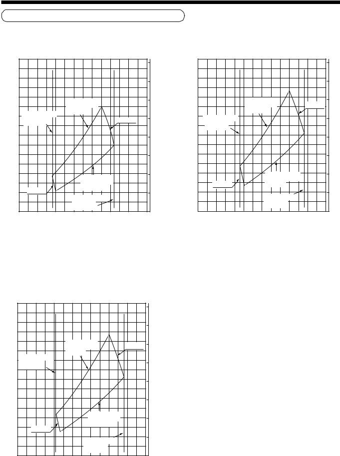
Static pressure characteristics of each model
|
Fig. 1 RAS-M10GDCV-E, RAS-M10GDV-E |
|
|||||||
|
80 |
|
|
|
|
|
|
8 |
|
|
|
|
|
|
|
|
|
|
|
|
70 |
|
|
|
|
|
|
7 |
|
|
|
|
|
|
|
|
|
|
|
|
60 |
|
|
Upper limit of |
|
|
6 |
External static pressure (mmAq) |
|
External static pressure (Pa) |
|
|
|
|
|
||||
|
|
|
external static |
|
|
|
|||
50 |
Air volume limit |
pressure |
|
|
|
||||
|
|
|
|
|
|||||
(Minimum) |
|
|
|
|
High tap |
5 |
|||
|
|
|
|
|
|||||
|
380m³/hr. |
|
|
|
|
|
|
||
40 |
|
|
|
|
|
|
4 |
||
|
|
|
|
|
|
|
|||
30 |
|
|
|
|
|
|
3 |
||
20 |
|
|
|
Lower limit of |
|
2 |
|||
|
|
|
|
|
|
|
|
||
|
|
|
|
|
external static |
|
|
|
|
|
10 |
Low tap |
|
|
pressure |
|
|
1 |
|
|
|
Air volume limit |
|
|
|
||||
|
|
|
|
|
|
|
|
||
|
|
|
|
(Minimum) |
|
|
|
|
|
|
0 |
|
|
720m³/hr. |
|
|
0 |
|
|
|
|
|
|
|
|
|
|
||
|
200 |
300 |
400 |
500 |
600 |
700 |
800 |
900 |
|
Air volume (m³/hr.)
|
Fig. 2 RAS-M13GDCV-E, RAS-M13GDV-E |
|
|||||||||
|
80 |
|
|
|
|
|
|
|
|
8 |
|
|
|
|
|
|
|
|
|
|
|
|
|
|
70 |
|
|
|
|
|
|
|
|
7 |
|
|
|
|
|
|
|
|
|
|
|
|
|
External static pressure (Pa) |
60 |
|
|
|
Upper limit of |
|
High tap |
6 |
External static pressure (mmAq) |
||
|
|
|
|
external static |
|
|
|||||
|
Air volume limit |
pressure |
|
|
|
|
|||||
50 |
|
|
|
|
|
|
|||||
(Minimum) |
|
|
|
|
|
|
5 |
||||
|
|
|
|
|
|
|
|||||
|
410m³/hr. |
|
|
|
|
|
|
|
|||
40 |
|
|
|
|
|
|
|
|
4 |
||
|
|
|
|
|
|
|
|
|
|||
30 |
|
|
|
|
|
|
|
|
3 |
||
20 |
|
|
|
|
Lower limit of |
|
|
2 |
|||
|
|
|
|
external static |
|
|
|||||
|
|
|
Low tap |
|
|
pressure |
|
|
|
|
|
|
|
|
|
|
|
|
|
|
|
|
|
|
10 |
|
|
|
|
Air volume limit |
|
|
1 |
|
|
|
|
|
|
|
|
|
|
|
|
||
|
|
|
|
|
|
(Minimum) |
|
|
|
|
|
|
|
|
|
|
|
780m³/hr. |
|
|
|
|
|
|
0 |
|
|
|
|
|
|
|
|
0 |
|
|
200 |
300 |
400 |
500 |
600 |
700 |
800 |
900 |
|
|
|
Air volume (m³/hr.)
Fig. 3 RAS-M16GDCV-E, RAS-M16GDV-E |
|
|||||||
80 |
|
|
|
|
|
|
8 |
|
|
|
|
|
|
|
|
|
|
70 |
|
|
|
|
|
|
7 |
|
|
|
|
|
|
|
|
|
|
60 |
|
|
Upper limit of |
|
|
6 |
Externalstatic pressure (mmAq) |
|
|
|
|
|
|
||||
|
|
|
external static |
|
High tap |
|||
|
|
|
pressure |
|
|
|
||
50 |
Air volume limit |
|
|
|
|
5 |
||
|
|
|
|
|
||||
|
(Minimum) |
|
|
|
|
|
|
|
|
430m³/hr. |
|
|
|
|
|
|
|
40 |
|
|
|
|
|
|
4 |
|
|
|
|
|
|
|
|
||
30 |
|
|
|
|
|
|
3 |
|
pressurestaticExternal(Pa) |
|
|
|
Lower limit of |
|
2 |
||
20 |
|
|
|
|
|
|||
|
|
|
|
external static |
|
|
|
|
|
Low tap |
|
pressure |
|
|
|
|
|
10 |
|
|
|
Air volume limit |
|
1 |
|
|
|
|
|
|
|
|
|
||
|
|
|
|
(Minimum) |
|
|
|
|
0 |
|
|
|
780m³/hr. |
|
|
0 |
|
|
|
|
|
|
|
|
||
200 |
300 |
400 |
500 |
600 |
700 |
800 |
900 |
|
Air volume (m³/hr.)
Model |
RAS- |
M10GDCV-E |
M13GDCV-E |
M16GDCV-E |
|
M10GDV-E |
M13GDV-E |
M16GDV-E |
|||
|
|
||||
|
|
|
|
|
|
Max. |
Air |
650 |
700 |
700 |
|
volume |
|||||
|
|
|
|||
capacity |
|
|
|
|
|
|
|
|
|
||
point |
Static |
54.9 |
63.7 |
63.7 |
|
|
pressure |
(5.6) |
(6.5) |
(6.5) |
|
|
|
|
|
|
|
|
Air |
720 |
780 |
780 |
|
Max. air |
volume |
||||
|
|
|
|||
|
|
|
|
||
volume |
Static |
35.3 |
41.2 |
41.2 |
|
|
|||||
|
pressure |
(3.6) |
(4.2) |
(4.2) |
|
|
|
|
|
|
|
Min. |
Air |
400 |
430 |
450 |
|
volume |
|||||
|
|
|
|||
capacity |
|
|
|
|
|
|
|
|
|
||
point |
Static |
10.8 |
12.7 |
13.7 |
|
|
pressure |
(1.1) |
(1.3) |
(1.4) |
|
|
|
|
|
|
|
|
Air |
380 |
410 |
430 |
|
Min. air |
volume |
||||
|
|
|
|||
|
|
|
|
||
volume |
Static |
18.6 |
21.6 |
23.5 |
|
|
|||||
|
pressure |
(1.9) |
(2.2) |
(2.4) |
|
|
|
|
|
|
Unit for static pressure : Pa (mmAq)
Unit for air volume : m³/hr.
8
4 AIR DUCTING WORK
Installation Reference
The air supply ducting work is classified into two ways, one is branched by the square ducts, and the other is branched by the round ducts. (Be sure to divide the air supply duct into three or more branches.)
<Square duct> |
<Round duct> |
In case of using the square duct, apply the thermal insulator of thickness by 25mm or more to the duct board. For the thermal insulator, use high-density glass wool of weight by 64kg/m3.
Duct board |
Weight of thermal |
|
insulator (glass wool) is |
|
64 kg/m³ or equivalent. |
|
25mm or more |
In case of using the round duct, use the thermal insulator of thickness by 25mm or more and inner diameter by 150mm or more to the duct board. (If the inner diameter is not enough, resistance generates, as the result, air does not flow smoothly and loss of the static pressure increases.) For the thermal insulator, use high-density glass wool of weight by 24kg/m3 or equivalent.
Weight of thermal insulator (glass wool) is
24 kg/m³ or equivalent.
25mm or more
Ø150mm or more
Connecting method of the duct
1. Supply air side
• Using 6 screws, mount the flange to the supply air port of the indoor unit. (Fig. 1)
‚ Make the square duct according to inner dimension of the flange. A x B .
Use a glass wool board with inside/outside finishing by 25mm-thickness and 64kg/m³-density.
ƒ Connect the flange and each type of duct. (Fig. 2)
Thermal insulator (50mm (w), 6mm (t))
|
Aluminum tape |
Seal |
|
Thermal insulator : |
|
|
(50mm-width) |
|
|
( 25mm (w), 6mm (t) ) |
|
|
|
|
|
25mm |
End |
|
|
|
B |
|
Indoor unit |
|
Square |
|
|
duct board |
|
|
(25mm) |
|
|
A |
|
Fig. 1 |
Fig. 2 |
CAUTION
Incomplete thermal insulation of the supply air flange and sealing may occur dewing resulted in falling of water drop.
9

<Square duct> |
<Round duct> |
Thermal insulator with sticking material (50mm-width, 6mm (t))
Aluminum tape (Seal : 50mm-width)
Thermal insulator |
Thermal insulator |
Thermal insulator |
|
with sticking material |
|||
at indoor unit side |
at indoor unit side |
||
(50mm-width, 6mm-thickness) |
|||
Stuck already at |
Stuck already at |
||
|
|||
(shipment from the factory) |
Aluminum tape |
(shipment from the factory) |
|
|
(Seal : 50mm-width) |
|
Fit to the arrow |
Screws |
|
(6 pieces) |
||
direction by pushing. |
||
Indoor unit side |
||
|
||
Attach by pushing to |
Flange |
|
(procured locally) |
||
the arrow direction. |
||
Seal/thermal insulator |
||
(Outside corner direction) |
||
with sticking material |
||
Square duct board |
||
(25mm-width, 6mm (t)) |
||
25mm-thickness, |
||
|
||
(64kg/m³ or equivalent) |
|
Fit to the arrow direction by pushing.
Round duct
Screws |
(6 pieces) |
Thermal insulator |
Flange |
Seal/thermal insulator |
25mm-thickness, |
|
with sticking material |
(24kg/m³ or equivalent ) |
|
(25mm-width, 6mm (t)) |
Fit the seal/thermal insulator (25mm-width, 6mm-thickness) by pushing to the arrow direction so that no clearance can be found between the flange and the round duct.
Fig. 2 (a) |
Fig. 2 (b) |
2. Return air side
Caution for Safety
When you do not connect the duct to the return air side (using steel and others), apply a protective measures so that your hands or fingers do not directly touch with the motor or other electric parts.
2-1. Return air from rear side
•Follow the procedure same as that for the supply air side. Flange mounting → Square duct making → Connecting work
2-2. Return air from lower side
•Remove the cover for return air at the lower side of the indoor unit, and attach the cover to the opening port at the rear side of the indoor unit.
Cover for return air
‚ Mount the flange to the place from where the cover for return air was removed.
ƒ Mount the square duct.
„ Arrange the flange and the square duct.
10
 Loading...