


 Loading...
Toshiba RAS-24UKP-E, RAS-18UA-E, RAS-24UA-E, RAS-18UAH-E, RAS-18UKHP-E SERVICE MANUAL
...FILE NO. SVM-01007
SERVICE MANUAL
AIR-CONDITIONER
SPLIT WALL TYPE
RAS-24UKHP-E / RAS-24UAH-E
RAS-24UKP-E / RAS-24UA-E
RAS-24UKPX / RAS-24UAX
RAS-24UKP-AR / RAS-24UA-AR
RAS-24UKPX-T/RAS-24UAX-T
RAS-18UKHP-E/RAS-18UAH-E
RAS-18UKP-E/RAS-18UA-E
RAS-18UKPX/RAS-18UAX
RAS-18UKP-AR/RAS-18UA-AR
RAS-18UKPX-T/RAS-18UAX-T
18 Class |
24 Class |
TCTC
CONTENT
1.SPECIFICATIONS
1-1 RAS-24UKHP-E/24UAH-E, RAS-24UKP-E/24UA-E RAS-24UKPX/24UAX, RAS-24UKP-AR/24UA-AR RAS-24UKPX-T/24UAX-T
1-2 RAS-18UKHP-E/18UAH-E, RAS-18UKP-E/18UA-E RAS-18UKPX/18UAX, RAS-18UKP-AR/18UA-AR
RAS-18UKPX-T/18UAX-T
2.CONSTRUCTION VIEWS
2-1 Indoor Unit (RAS-24UKHP-E, 24UKP-E, 24UKPX, 24UKP-AR, 24UKPX-T) 2-2 Indoor Unit (RAS-18UKHP-E, 18UKP-E, 18UKPX, 18UKP-AR, 18UKPX-T) 2-3 Outdoor Unit (RAS-24UAH-E, 24UA-E, 24UAX, 24UA-AR, 24UAX-T)
2-4 Outdoor Unit (RAS-18UAH-E, 18UA-E, 18UAX, 18UA-AR, 18UAX-T)
3.WIRING DIAGRAM
3-1 RAS-24UKHP-E/RAS-24UAH-E 3-2 RAS-24UKP-E/RAS-24UA-E
RAS-24UKPX/RAS-24UAX RAS-24UKP-AR/RAS-24UA-AR RAS-24UKPX-T/RAS-24UAX-T
3-3 RAS-18UKHP-E/RAS-18UAH-E 3-4 RAS-18UKP-E/RAS-18UA-E
RAS-18UKPX/RAS-18UAX RAS-18UKP-AR/RAS-18UA-AR
RAS-18UKPX-T/RAS-18UAX-T
4.SPECIFICATION OF ELECTRICAL PARTS
4-1 Indoor Unit (RAS-24UKHP-E, 18UKHP-E) 4-2 Outdoor Unit (RAS-24UAH-E)
4-3 Outdoor Unit (RAS-18UAH-E)
4-4 Indoor Unit (RAS-24UKP-E, 24UKPX, 24UKP-AR, 24UKPX-T, 18UKP-E, 18UKPX, 18UKP-AR, 18UKPX-T)
4-5 Outdoor Unit (RAS-24UA-E, 24UAX, 24UA-AR, 24UAX-T) 4-6 Outdoor Unit (RAS-18UA-E, 18UAX, 18UA-AR, 18UAX-T)
5.REFRIGERATION CYCLE DIAGRAM
5-1 RAS-24UKHP-E/24UAH-E 5-2 RAS-24UKP-E/24UA-E
RAS-24UKPX/24UAX RAS-24UKP-AR/24UA-AR RAS-24UKPX-T/24UAX-T
5-3 RAS-18UKHP-E/18UAH-E, RAS-18UKP-E/18UA-E 5-4 RAS-18UKP-E/18UA-E
RAS-18UKPX/18UAX RAS-18UKP-AR/18UA-AR RAS-18UKPX-T/18UAX-T
–1 –
TCTC Service Manual 24/18UKHP-E (EN) File No. SVM-01007
6.CONTROL BLOCK DIAGRAM
6-1 RAS-24UKHP-E, 18UKHP-E
6-2 RAS-24UKP-E, 24UKPX, 24UKP-AR, 24UKPX-T RAS-18UKP-E, 18UKPX, 18UKP-AR, 18UKPX-T
7.OPERATION DESCRIPTION
7-1 Outline of Air Conditioner Control
7-2 Description of Operation Circuit
7-3 ECO Mode
7-4 HiPOWER Mode
7-5 High-Temperature Limit Control
7-6 Low-Temperature Limit Control
7-7 Defrosting Operation
7-8 Auto Restart Function
7-9 Filter Check Lamp
8.INSTALLATION PROCEDURE
8-1 Safety Cautions
8-2 Installation Diagram of Indoor and Outdoor Units 8-3 Installation
8-4 Indoor Unit
8-5 Outdoor Unit
8-6 Other
9.TROUBLESHOOTING CHART
9-1 Troubleshooting Procedure
9-2 Basic Check Items
9-3 Primary Judgement
9-4 Self-Diagnosis by Remote Control (Check Code) 9-5 How to Diagnose Faulty Part
9-6 Troubleshooting for Indoor Unit
9-7 Troubleshooting for Wiring (Interconnect cable and Serial Signal Wire) 9-8 Troubleshooting for P.C. Board
9-9 Troubleshooting for Remote Control
10.TROUBLESHOOTING CHART
10-1 Indoor Unit
10-2 Outdoor Unit (RAS-24UAH-E, 24UA-E, 24UAX, 24UA-AR, 24UAX-T) 10-3 Outdoor Unit (RAS-18UAH-E, 18UA-E, 18UAX, 18UA-AR, 18UAX-T)
11.EXPLODED VIEWS AND PARTS LIST
11-1 Indoor Unit (1)
11-2 Indoor Unit (2)
11-3 Indoor Unit (3)
11-4 Outdoor Unit (1)
11-5 Outdoor Unit (2)
11-6 Outdoor Unit (3)
11-7 Outdoor Unit (4)
11-8 Outdoor Unit (5)
–2 –
TCTC Service Manual 24/18UKHP-E (EN) File No. SVM-01007

1. SPECIFICATIONS
1-1 |
|
|
|
|
|
|
|
|
|
|
|
|
|
ITEM |
MODEL RAS-24UKHP-E/24UAH-E |
RAS-24UKP-E/24UA-E RAS-24UKPX/24UAX |
RAS-24UKP-AR/24UA-AR RAS-24UKPX-T/24UAX-T |
||||||||||
|
|
Cooling |
Heating |
Cooling |
Cooling |
Cooling |
Cooling |
||||||
Capacity |
|
kW |
220V 240V |
220V |
240V |
220V |
240V |
220V |
240V |
220V |
240V |
220V |
|
|
6.30 |
6.30 |
6.80 |
6.90 |
6.40 |
6.45 |
6.40 |
6.45 |
6.40 |
6.45 |
6.40 |
||
|
|
|
|||||||||||
|
|
Phase |
|
|
|
|
|
|
|
1Ø |
|
|
|
Power source |
|
V |
|
|
|
|
|
220 – 240 |
|
|
|
220 |
|
|
|
Hz |
|
|
|
|
|
|
|
50 |
|
|
|
Power consumption |
W |
2430 |
2510 |
2430 |
2530 |
2350 |
2440 |
2350 |
2440 |
2350 |
2440 |
2350 |
|
Power factor |
|
% |
96 |
91 |
96 |
91 |
96 |
91 |
96 |
91 |
96 |
91 |
96 |
|
|
|
220V |
240V |
220V |
240V |
220V |
240V |
220V |
240V |
220V |
240V |
220V |
Running current |
|
A |
0.3/ |
0.3/ |
0.3/ |
0.3/ |
0.3/10.9 |
0.3/10.8 |
0.3/10.9 |
0.3/10.8 |
0.3/10.9 |
0.3/10.8 |
0.3/10.9 |
|
Indoor / Outdoor |
11.2 |
11.1 |
11.2 |
11.2 |
||||||||
|
|
|
|
|
|
|
|
||||||
Starting current |
|
A |
|
60 |
|
|
|
|
|
|
50 |
|
|
Moisture removal |
|
lit/h |
|
2.5 |
|
|
|
|
|
2.7 |
|
|
|
Noise |
Indoor (H/M/L) |
dB |
|
|
|
|
|
|
45/41/37 |
|
|
|
|
Outdoor (220-240V) |
dB |
56-57 |
57-58 |
|
|
56-57 |
|
|
56 |
||||
|
|
|
|
|
|||||||||
Refrigerant |
Name of refrigerant |
|
|
|
|
|
|
|
|
R22 |
|
|
|
Rated amount |
kg |
|
|
|
|
|
|
|
1.63 |
|
|
|
|
|
|
|
|
|
|
|
|
|
|
|
|||
Refrigerant control |
|
|
|
|
|
|
|
|
Capillary tube |
|
|
|
|
Interconnection |
Gas side size |
mm |
|
|
|
|
|
|
Ø 15.88 |
|
|
|
|
pipe |
Connection type |
|
|
|
|
|
|
|
Flare connection |
|
|
|
|
|
Liquid side size |
mm |
|
|
|
|
|
|
Ø 6.35 |
|
|
|
|
|
Connection type |
|
|
|
|
|
|
|
Flare connection |
|
|
|
|
|
Maximum length |
m |
|
|
|
|
|
|
|
15*1 |
|
|
|
|
(One way) |
|
|
|
|
|
|
|
25*2 |
|
|
|
|
|
|
|
|
|
|
|
|
|
|
|
|
||
|
Maximum height difference |
|
|
|
|
|
|
|
10 |
|
|
|
|
|
|
m |
|
|
|
|
|
|
|
|
|
|
|
|
|
|
|
|
|
|
|
|
|
|
|
|
|
INDOOR UNIT |
|
|
RAS-24UKHP-E |
RAS-24UKP-E |
RAS-24UKPX |
RAS-24UKP-AR |
RAS-24UKPX-T |
||||||
Dimensions |
Height |
mm |
|
|
|
|
|
|
|
298 |
|
|
|
|
Width |
mm |
|
|
|
|
|
|
|
998 |
|
|
|
|
Depth |
mm |
|
|
|
|
|
|
|
208 |
|
|
|
Net weight |
|
kg |
|
|
|
|
|
|
|
12 |
|
|
|
Evaporator type |
|
|
|
|
|
|
|
|
Finned tube |
|
|
|
|
Indoor fan type |
|
|
|
|
|
|
|
|
Cross flow fan |
|
|
|
|
Air volume |
High fan |
m3/h |
|
|
|
|
|
|
|
950 |
|
|
|
|
Medium fan |
m3/h |
750 |
800 |
|
|
|
|
750 |
|
|
||
|
Low fan |
m3/h |
600 |
650 |
|
|
|
|
600 |
|
|
||
Fan motor output |
|
W |
|
|
|
|
|
|
|
30 |
|
|
|
Air filter |
|
|
|
|
|
|
|
Honeycomb woven filter with PP frame |
|
|
|||
OUTDOOR UNIT |
|
|
RAS-24UAH-E |
RAS-24UA-E |
RAS-24UAX |
RAS-24UA-AR |
RAS-24UAX-T |
||||||
Dimensions |
Height |
mm |
|
|
|
|
|
|
|
690 |
|
|
|
|
Width |
mm |
|
|
|
|
|
|
|
880 |
|
|
|
|
Depth |
mm |
|
|
|
|
|
|
|
310 |
|
|
|
Net weight |
|
kg |
|
66 |
|
65 |
|
|
65 |
|
65 |
65 |
|
Condenser type |
|
|
|
|
|
|
|
|
Finned tube |
|
|
|
|
Outdoor fan type |
|
|
|
|
|
|
|
|
Propeller fan |
|
|
|
|
Airflow volume |
|
|
3380 |
3560 |
3380 |
3560 |
3380 |
3560 |
3380 |
3560 |
3380 |
||
Fan motor output |
|
W |
|
|
|
|
|
|
|
65 |
|
|
|
Compressor |
Model |
|
PH310X3-4MM |
|
|
|
PH280X3-4MS |
|
|
||||
|
Output |
W |
|
2200 |
|
|
|
|
|
2000 |
|
|
|
Safety device |
|
|
IOL, Td Sensor |
|
|
|
|
IOL |
|
|
|||
Louver type |
|
|
|
|
|
|
|
|
Automatic louver |
|
|
|
|
Usable outdoor temperature range |
°C |
15 ~ 43 |
-10 ~ 24 |
15 ~ 43 |
15 ~ 43 |
15 ~ 52 |
15 ~ 43 |
||||||
|
|
|
|
|
|
|
– 3 – |
|
|
|
|
|
|
TCTC Service Manual 24/18UKHP-E (EN) File No. SVM-01007
1-2 |
|
|
|
|
|
|
|
|
|
|
|
|
|
ITEM |
|
MODEL |
RAS-18UKHP-E/18UAH-E |
RAS-18UKP-E/18UA-E |
RAS-18UKPX/18UAX |
RAS-18UKP-AR/18UA-AR RAS-18UKPX-T/18UAX-T |
|||||||
|
|
Cooling |
Heating |
Cooling |
Cooling |
Cooling |
Cooling |
||||||
Capacity |
|
kW |
220V 240V |
220V |
240V |
220V |
240V |
220V |
240V |
220V |
240V |
220V |
|
|
5.05 |
5.05 |
5.80 |
5.90 |
5.20 |
5.25 |
5.20 |
5.25 |
5.20 |
5.25 |
5.20 |
||
|
|
|
|||||||||||
|
|
Phase |
|
|
|
|
|
|
|
1Ø |
|
|
|
Power source |
|
V |
|
|
|
|
|
220 – 240 |
|
|
|
220 |
|
|
|
Hz |
|
|
|
|
|
|
|
50 |
|
|
|
Power consumption |
W |
1920 |
2040 |
1800 |
1950 |
1870 |
1950 |
1870 |
1950 |
1920 |
2040 |
1870 |
|
Power factor |
|
% |
95 |
88 |
94 |
86 |
95 |
88 |
95 |
88 |
95 |
88 |
95 |
|
|
|
220V |
240V |
220V |
240V |
220V |
240V |
220V |
240V |
220V |
240V |
220V |
Running current |
|
A |
0.2/ |
0.2/ |
0.2/ |
0.2/ |
0.2/8.75 |
0.2/9.0 |
0.2/8.75 |
0.2/9.0 |
0.2/9.0 |
0.2/9.5 |
0.2/8.75 |
|
Indoor / Outdoor |
9.0 |
9.5 |
8.5 |
9.2 |
||||||||
|
|
|
|
|
|
|
|
||||||
Starting current |
|
A |
|
|
|
|
|
|
|
40 |
|
|
|
Moisture removal |
|
lit/h |
|
|
|
|
|
|
|
2 |
|
|
|
Noise |
Indoor (H/M/L) |
dB |
|
|
|
|
|
|
42/39/35 |
|
|
|
|
|
Outdoor (220-240V) dB |
52-53 |
53-54 |
51 |
52 |
51 |
52 |
52 |
53 |
51 |
|||
Refrigerant |
Name of refrigerant |
|
|
|
|
|
|
|
R22 |
|
|
|
|
Rated amount |
kg |
|
1.29 |
|
|
1.06 |
|
|
1.17 |
1.06 |
|||
|
|
|
|
|
|
||||||||
Refrigerant control |
|
|
|
|
|
|
|
|
Capillary tube |
|
|
|
|
Interconnection |
Gas side size |
mm |
|
|
|
|
|
|
Ø 12.7 |
|
|
|
|
pipe |
Connection type |
|
|
|
|
|
|
|
Flare connection |
|
|
|
|
|
Liquid side size |
mm |
|
|
|
|
|
|
Ø 6.35 |
|
|
|
|
|
Connection type |
|
|
|
|
|
|
|
Flare connection |
|
|
|
|
|
Maximum length |
m |
|
|
|
|
|
|
|
15*1 |
|
|
|
|
(One way) |
|
|
|
|
|
|
|
20*2 |
|
|
|
|
|
|
|
|
|
|
|
|
|
|
|
|
||
|
Maximum height difference |
|
|
|
|
|
|
|
8 |
|
|
|
|
|
|
m |
|
|
|
|
|
|
|
|
|
|
|
|
|
|
|
|
|
|
|
|
|
|
|
|
|
INDOOR UNIT |
|
|
|
RAS-18UKHP-E |
RAS-18UKP-E |
|
RAS-18UKPX |
|
RAS-18UKP-AR |
RAS-18UKPX-T |
||||||||
Dimensions |
Height |
mm |
|
|
|
|
|
|
|
|
298 |
|
|
|
|
|
||
|
Width |
mm |
|
|
|
|
|
|
|
|
998 |
|
|
|
|
|
||
|
Depth |
mm |
|
|
|
|
|
|
|
|
208 |
|
|
|
|
|
||
Net weight |
|
|
kg |
|
|
|
|
|
|
|
|
12 |
|
|
|
|
|
|
Evaporator type |
|
|
|
|
|
|
|
|
|
|
Finned tube |
|
|
|
|
|
||
Indoor fan type |
|
|
|
|
|
|
|
|
|
|
Cross flow fan |
|
|
|
|
|
||
Air volume |
High fan |
m3/h |
750 |
|
800 |
|
|
|
|
|
|
750 |
|
|
|
|||
|
|
|
|
|
|
|
|
|
|
|
|
|
|
|
|
|
|
|
|
Medium fan |
m3/h |
650 |
|
700 |
|
|
|
|
|
|
650 |
|
|
|
|||
|
Low fan |
m3/h |
530 |
|
570 |
|
|
|
|
|
|
530 |
|
|
|
|||
Fan motor output |
|
|
W |
|
|
|
|
|
|
|
|
30 |
|
|
|
|
|
|
Air filter |
|
|
|
|
|
|
|
|
Honeycomb woven filter with PP frame |
|
|
|||||||
OUTDOOR UNIT |
|
|
|
RAS-18UAH-E |
RAS-18UA-E |
|
RAS-18UAX |
|
RAS-18UA-AR |
RAS-18UAX-T |
||||||||
Dimensions |
Height |
mm |
|
|
|
|
|
|
|
|
538 |
|
|
|
|
|
||
|
|
|
|
|
|
|
|
|
|
|
|
|
|
|
|
|
|
|
|
Width |
mm |
|
|
|
|
|
|
|
|
830 |
|
|
|
|
|
||
|
Depth |
mm |
|
|
|
|
|
|
|
|
300 |
|
|
|
|
|
||
Net weight |
|
|
kg |
|
54 |
|
|
50 |
|
|
|
54 |
|
50 |
||||
Condenser type |
|
|
|
|
|
|
|
|
|
|
Finned tube |
|
|
|
|
|
||
Outdoor fan type |
|
|
|
|
|
|
|
|
|
|
Propeller fan |
|
|
|
|
|
||
Airflow volume |
|
|
|
2105 |
|
2310 |
1830 |
2010 |
|
1830 |
|
2010 |
|
2105 |
|
2310 |
1830 |
|
Fan motor output |
|
|
W |
|
65 |
|
|
42 |
|
|
|
65 |
|
42 |
||||
Compressor |
Model |
|
|
|
|
|
|
|
|
PH250X3-4LM |
|
|
|
|
|
|||
|
|
|
|
|
|
|
|
|
|
|
|
|
|
|
|
|
|
|
|
Output |
W |
|
|
|
|
|
|
|
|
1500 |
|
|
|
|
|
||
Safety device |
|
|
|
IOL, Td Sensor |
|
|
|
|
|
|
IOL |
|
|
|||||
Louver type |
|
|
|
|
|
|
|
|
|
|
Automatic louver |
|
|
|
|
|
||
Usable outdoor temperature range |
°C |
15 ~ 43 |
|
-10 ~ 24 |
15 ~ 43 |
|
15 ~ 43 |
|
15 ~ 52 |
|
15 ~ 43 |
|||||||
– 4 –
TCTC Service Manual 24/18UKHP-E (EN) File No. SVM-01007

Note : 1
• Capacity is based on the following temperature conditions.
|
Condition |
|
JIS C9612-1994 |
Temperature |
|
Cooling |
Heating |
|
|
||
Indoor unit inlet air temperature |
(DB) |
27 °C |
20 °C |
|
|
|
|
|
(WB) |
19 °C |
12 °C |
Outdoor unit inlet air temperature |
(DB) |
35 °C |
7 °C |
|
|
|
|
|
(WB) |
24 °C |
6 °C |
Note : 2
• Charge refrigerant according to the table below.
|
|
RAS-24UKHP-E/24UAH-E |
RAS-18UKHP-E/18UAH-E |
|
|
RAS-24UKP-E/24UA-E |
RAS-18UKP-E/18UA-E |
|
Refrigerant |
RAS-24UKPX/24UAX |
RAS-18UKPX/18UAX |
|
|
RAS-24UKP-AR/24UA-AR |
RAS-18UKP-AR/18UA-AR |
|
|
RAS-24UKPX-T/24UAX-T |
RAS-18UKPX-T/18UAX-T |
*1 |
No need to charge |
15m or less |
15m or less |
|
refrigerant |
||
|
|
|
|
*2 |
Need to charge |
Over 15m up to 25m (20g/m) |
Over 15m up to 20m (20g/m) |
|
refrigerant |
||
|
|
|
– 5 –
TCTC Service Manual 24/18UKHP-E (EN) File No. SVM-01007
2. CONSTRUCTION VIEWS
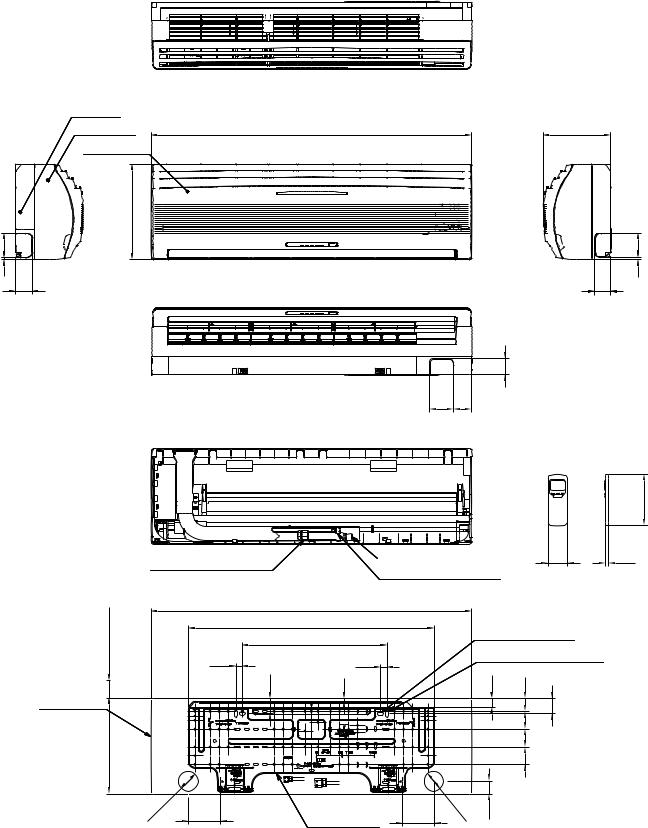
2-1. Indoor Unit RAS-24UKHP-E RAS-24UKP-E RAS-24UKPX RAS-24UKP-AR RAS-24UKPX-T
Back body |
|
|
Front panel |
998 |
208 |
Grille inlet |
|
|
298 |
|
|
75 |
|
75 |
7 |
|
8 |
51 |
|
50 |
Knock out system |
|
Knock out system |
50 |
75 56
55 or more
Outline of indoor unit
298
Minimumdistance |
toceiling |
160
Connecting pipe (0.39m) |
Drain hose (0.54m) |
57 |
18 |
|
(Flare ø15.88) |
Connecting pipe (0.49m) |
Wireless remote |
||
(Flare ø6.35) |
||||
|
||||
|
control |
|
||
|
998 |
|
||
|
|
|
||
|
763.5 |
|
|
|
|
For stud bolt (ø6) |
|
||
|
450 |
|
|
|
For stud bolt (ø8 – ø10)
20 |
|
20 |
48 |
10 |
29 |
41 |
48 |
55 55 |
|
55 |
|
ø65
100 |
Installation |
100 |
Plate outline |
– 6 –
ø 65
40
TCTC Service Manual 24/18UKHP-E (EN) File No. SVM-01007

2-2. Indoor Unit RAS-18UKHP-E RAS-18UKP-E RAS-18UKPX RAS-18UKP-AR RAS-18UKPX-T
Back body |
|
|
Front panel |
998 |
208 |
Grille inlet |
|
|
298 |
|
|
75 |
|
75 |
7 |
|
8 |
51 |
|
50 |
Knock out system |
|
Knock out system |
50 |
75 56
55 or more
Outline of indoor unit
298
Minimumdistance |
toceiling |
160
Connecting pipe (0.39m) |
Drain hose (0.54m) |
57 |
18 |
|
(Flare ø12.7) |
Connecting pipe (0.49m) |
Wireless remote |
||
(Flare ø6.35) |
||||
|
||||
|
control |
|
||
|
998 |
|
||
|
|
|
||
|
763.5 |
|
|
|
|
For stud bolt (ø6) |
|
||
|
450 |
|
|
|
For stud bolt (ø8 – ø10)
20 |
|
20 |
48 |
10 |
29 |
41 |
48 |
55 55 |
|
55 |
|
ø65
100 |
Installation |
100 |
Plate outline |
– 7 –
ø 65
40
TCTC Service Manual 24/18UKHP-E (EN) File No. SVM-01007

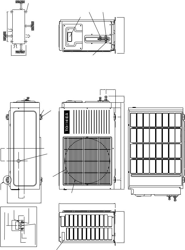
2-3. Outdoor Unit RAS-24UAH-E RAS-24UA-E RAS-24UAX RAS-24UA-AR
RAS-24UAX-T |
|
|
12x18ø-4 10ø–8øfor |
bolt |
|
|
|
|
|
|
|
|
|||
|
|
|
|
|
|
|
|
|
|
|
|
||||
ofanchorbolt |
600 |
600or |
more |
Airinlet |
600 |
ormore |
anchor |
Electric Partscover |
Liquidside |
(Flareø6.35) |
Gasside |
(Flareø15.88) |
ServicePort |
12 |
364 |
Mountingdimension |
or100 |
more |
100 moreor |
|
23 |
|
|
|
|
|
12 |
||||
|
|
|
|
|
|
outletAir |
|
310 |
|
|
|
|
|
(pitch)340 |
|
|
|
|
6852 |
|
|
|
|
Handle |
|
|
|
|
88 |
74 |
|
|
|
|
|
|
|
|
|
|
|
|
|
|
|
||
|
|
|
|
|
|
|
|
|
|
|
|
|
|
|
|
140
ø25 Drain outlet
120 |
600 |
bolt) |
880 |
A |
12x18holes |
ø8–ø10anchor |
|
|
4-ø |
(for |
|
|
8.63 |
|
690 |
|
|
|
|
|
340 |
|
|
Drawing |
|
hole |
600 |
12x18ø |
|
|
|
27 |
Detail |
|
50 |
A |
|
340 |
|
|
– 8 –
Handle
TCTC Service Manual 24/18UKHP-E (EN) File No. SVM-01007
2-4. Outdoor Unit
RAS-18UAH-E RAS-18UA-AR RAS-18UA-E RAS-18UAX-T RAS-18UAX
|
|
ormore |
4xø11x14 forø8-ø10 |
anchorbolt |
|
|
600 |
|
|
dimension |
600 Airinlet |
|
600or more |
|
Installation |
more |
Airinlet |
more Air |
outlet |
|
or |
|
or |
|
|
100 |
325 |
100 |
|
|
|
|
|
8-ø6 holes (for fixing outdoor unit) 6-ø11x14 holes (for ø8 – ø10 anchor bolt)
Electric Partscover |
Liquidside (Flareø6.35) |
Gasside (Flareø12.7) |
344
Service Port
54 |
91 |
|
160 |
|
50 |
|
90 |
|
|
|
|
Drainoutlet |
600 830 |
120 |
|
|
|
ø25 |
|
A |
|
|
|
Fanguard |
90 |
|
|
52 |
|
|
ø420 |
|
|
325 |
|
|
538 |
|
|
|
|
|
|
ADetailDrawing 600 |
R10 |
ø6hole |
ø11x14hole |
Handle |
300 |
|
|
|
|
|
– 9 – |
TCTC Service Manual 24/18UKHP-E (EN) File No. SVM-01007
3. WIRING DIAGRAM
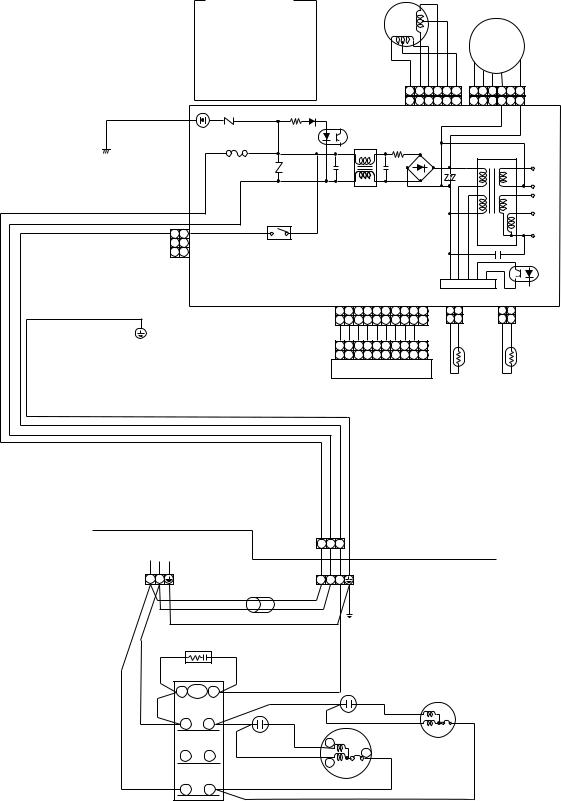
3-1. RAS-24UKHP-E/RAS-24UAH-E
COLOR IDENTIFICATION
BRW : BROWN
RED : RED
WHI : WHITE
YEL : YELLOW
BLU : BLUE
BLK : BLACK
GRY : GRAY
PNK : PINK
ORN : ORANGE
GRN&YEL : GREEN &YELLOW
GRN : GREEN
BLK |
R22 |
R09 |
P04 |
VARISTOR |
|
SG01 |
|
DSA
T6. 3A 250V
F01 FUSE
R21
BLK |
CN30 |
WHI |
CN31 |
RED |
|
GRN&YEL
CN23
POWER SUPPLY |
INDOOR |
1 2 3 |
INDOOR |
|
TERMINAL |
||||
220-240 V~, 50 Hz |
BLOCK |
|
UNIT |
|
POWER |
|
OUTDOOR |
|
OUTDOOR |
TERMINAL |
L N i |
TERMINAL |
1 2 3 i UNIT |
|
BLOCK |
|
BLOCK |
|
|
|
BLK |
FERRITE CORE |
|
|
|
|
|
|
|
|
RED |
|
|
GRN&YEL |
|
GRN&YEL |
|
|
i |
BLK |
RED |
|
|
CHASSIS |
|
|
|
||
MAGNETIC SWITCH
T S R
A1
52C
A2
W V U
|
CAPACITOR |
|
CAPACITOR |
|
RED |
|
|
RED |
|
WHI |
S |
BLK |
WHI |
|
PNK |
C |
RED |
BLK |
|
|
|
|||
R
LOUVER |
|
|
|
|
|
|
FAN MOTOR |
|||||||
|
|
|
|
|
|
|
|
|
|
|||||
MOTOR |
|
|
|
|
|
|
|
|
|
|
||||
|
|
|
|
|
|
|
|
|
|
|
DC MOTOR |
|
||
|
|
|
|
|
|
BLU PNK YEL |
ORN |
RED BRW |
|
6 5 4 |
|
|
|
|
|
|
|
|
|
|
|
6 5 4 3 |
2 1 |
|
3 |
|
1 |
||
|
|
|
|
|
|
|
6 5 4 3 2 1 |
|
6 5 4 |
3 |
|
1 |
||
|
|
|
|
|
|
|
CN 07 |
|
CN 10 |
|
|
|
||
IC04 |
|
|
|
|
|
|
|
|
|
|
|
|
|
|
|
|
L01 |
R01 |
DB01 |
|
|
|
|
|
|
||||
|
|
|
|
|
|
|
T01 |
|
|
|||||
|
|
|
|
|
|
|
|
|
|
|
|
|
||
C15 |
|
|
|
C01 |
|
|
|
|
|
|
|
DC15V |
||
|
|
|
|
|
|
|
|
|
C02 |
|
|
DC0V |
||
|
|
|
|
|
|
|
|
|
|
|
|
|
|
|
|
|
|
|
|
|
|
|
|
|
|
|
|
|
DC12V |
|
|
|
|
|
|
|
|
|
|
|
|
|
|
DC7V |
MAIN P.C. BOARD |
|
|
|
|
|
|
DC0V |
|||||||
|
|
|
C06 |
|
|
|
||||||||
|
|
(MCC-821) |
|
|
|
|
|
|
||||||
|
|
|
|
|
|
|
|
IC02 |
||||||
|
|
|
|
|
|
|
|
|
|
|
|
|
|
|
|
|
|
|
|
|
|
|
|
|
|
IC |
|
|
|
|
|
|
CN13 |
|
|
|
|
CN03 |
IC01 |
|
|
|
||
|
|
|
|
|
|
|
CN01 |
|
||||||
1 |
2 3 |
4 |
5 6 |
7 |
8 |
9 10 |
|
1 2 |
|
|
1 2 |
|
||
1 |
2 3 |
4 |
5 6 |
7 |
8 |
9 10 |
|
1 2 |
|
|
1 2 |
|
||
BLU BLU BLU |
BLU |
BLU BLU |
BLU |
BLU |
BLU WHI |
|
BLK BLK |
THERMOBLK |
BLK |
HEAT |
||||
1 |
2 |
3 |
4 |
5 6 |
7 |
8 |
9 10 |
CN25 |
SENSOR |
|
|
|||
|
|
EXCHANGER |
||||||||||||
1 |
2 3 |
4 |
5 6 |
7 |
8 |
9 10 |
|
(TA) |
|
|
||||
INFRARED RAYS RECEIVE |
|
|
|
|
|
|
SENSOR |
|||||||
|
|
|
|
|
|
(TC) |
||||||||
AND INDICATION PARTS |
|
|
|
|
|
|
|
|||||||
TRANSFORMER
BLK |
1 |
1 |
MAIN P.C. BOARD (MCC-1275) |
|
|
|
|
|
|
|
DISCHARGE |
||||
BLK |
|
2 |
CN06 |
|
|
||
|
|
|
PIPE |
||||
3 3 |
|
|
|
||||
RED 1 1 |
|
|
|
SENSOR (TD) |
|||
CN05 |
|
1 1 |
BLK |
||||
RED |
3 3 |
|
CN07 2 |
|
|
||
TNR |
|
3 3 |
BLK |
||||
BLK |
1 1 |
R74 DSA |
|
|
|
|
|
BLK |
3 3 |
F01 |
|
|
|
|
|
T5A 250VAC |
|
|
|
BLK |
|||
WHI 5 5 |
TNR |
1 |
1 |
||||
|
CN08 2 |
|
|
||||
|
|
|
CN01 |
R73 |
|
|
|
RED |
|
|
|
3 |
3 |
BLK |
|
7 7 |
|
|
|||||
GRY 9 9 |
|
|
|
HEAT |
|||
|
|
|
EXCHANGER |
||||
|
|
|
|
|
|
SENSOR (TE) |
|
|
1 |
1 |
|
|
|
|
|
|
3 |
3 |
CN04 |
|
|
|
|
|
|
|
RY07 |
|
|
|
|
|
|
5 |
|
|
|
|
|
|
|
|
|
|
|
|
|
BLU 1 1 |
CN11 |
|
|
|
|
||
|
|
|
|
|
|
|
|
YEL 3 3 |
CR11 |
RY05 |
|
|
|
||
BLK 1 1 |
CN02 |
|
|
|
|
||
|
|
|
|
|
|
|
|
BLK 3 3 |
CR12 |
TNR R96 |
|
|
|
||
COIL FOR |
|
|
|
|
|
|
|
4 WAY VALVE |
|
|
|
|
|
|
|
|
|
|
|
ICO7 |
|
|
|
|
|
|
CN03 |
|
|
|
|
|
|
|
1 |
3 |
|
|
|
|
|
|
1 |
|
|
|
|
BLK
COMPRESSOR |
FAN MOTOR |
|
– 10 – |
TCTC Service Manual 18/24UKHP-E (EN) File No. SVM-01006
3-2. RAS-24UKP-E/RAS-24UA-E RAS-24UKPX/RAS-24UAX RAS-24UKP-AR/RAS-24UA-AR RAS-24UKPX-T/RAS-24UAX-T
COLOR IDENTIFICATION |
|
|
|
|
|
|
|
||
|
BRW : BROWN |
|
|
|
|
|
FAN MOTOR |
||
|
RED : RED |
|
LOUVER |
|
|
|
|||
|
|
|
|
|
|
|
|
||
|
WHI : WHITE |
|
|
|
|
|
|
|
|
|
|
MOTOR |
|
|
|
|
|
|
|
|
YEL : YELLOW |
|
|
|
|
|
|
|
|
|
BLU : BLUE |
|
|
|
|
|
DC MOTOR |
|
|
|
BLK : BLACK |
|
|
|
|
|
|
|
|
|
GRY : GRAY |
|
|
|
|
ORN RED BRW |
|
|
|
|
PNK : PINK |
|
|
BLU |
PNK YEL |
|
|
|
|
|
ORN : ORANGE |
|
|
|
|
|
|||
|
|
|
|
|
|
|
|
|
|
GRN&YEL : GREEN & YELLOW |
|
6 5 4 3 2 1 |
6 5 4 |
3 |
1 |
||||
|
GRN : GREEN |
|
|
||||||
|
|
|
|
6 5 4 |
3 2 1 |
6 5 4 |
3 |
1 |
|
BLK |
R22 |
R09 |
|
|
CN 07 |
CN 10 |
|
|
|
P04 |
VARISTOR |
|
IC04 |
|
|
|
|
|
|
SG01 |
|
|
|
|
|
|
|
|
|
DSA |
T6.3A 250V |
|
L01 |
R01 |
DB01 |
|
|
|
|
|
|
T01 |
|
||||||
|
|
|
|
|
|
|
|
||
|
|
F01 FUSE |
C15 |
|
|
|
C01 |
|
|
|
DC15V |
||
|
|
R21 |
|
|
|
|
|
|
|||||
|
|
|
|
|
|
|
|
|
|
|
C02 |
DC0V |
|
|
|
|
|
|
|
|
|
|
|
|
|
|
|
|
|
|
|
|
|
|
|
|
|
|
|
|
DC12V |
BLK |
CN30 |
|
|
|
|
|
|
|
|
|
|
DC7V |
|
WHI |
CN31 |
|
|
|
|
|
|
|
|
|
|
||
|
|
|
|
|
|
|
|
|
|
|
|||
RED |
CN27 1 |
1 |
MAIN P.C. BOARD |
|
|
DC0V |
|||||||
|
|
RY04 |
|
C06 |
|
||||||||
|
|
|
|
(MCC-821) |
|
|
|||||||
|
|
3 |
|
|
|
|
|||||||
|
|
|
|
|
|
IC02 |
|||||||
|
|
|
|
|
|
|
|
|
|
|
|
|
|
|
|
|
|
|
|
|
|
|
|
|
|
IC |
|
|
|
|
|
|
|
CN13 |
|
|
|
CN03 |
IC01 |
|
|
|
|
|
|
|
|
|
|
|
CN01 |
|
|||
GRN&YEL |
|
1 |
2 3 |
4 |
5 6 |
7 |
8 |
9 10 |
1 2 |
1 2 |
|
||
|
1 |
2 3 |
4 |
5 6 |
7 |
8 |
9 10 |
1 2 |
1 2 |
|
|||
|
|
|
|
||||||||||
|
|
|
BLU BLU BLU |
BLU |
BLU BLU |
BLU |
BLU |
BLU WHI |
BLK BLK |
BLK BLK |
|
||
|
|
|
1 |
2 |
3 |
4 |
5 6 |
7 |
8 |
9 10 |
CN25 |
THERMO |
HEAT |
|
|
|
1 |
2 3 |
4 |
5 6 |
7 |
8 |
9 10 |
||||
|
|
|
INFRARED RAYS RECEIVE |
|
SENSOR |
EXCHANGER |
|||||||
|
|
|
|
(TA) |
SENSOR |
||||||||
|
|
|
AND INDICATION PARTS |
|
|||||||||
|
|
|
|
|
(TC) |
||||||||
|
|
|
|
|
|
|
|
|
|
|
|
|
|
POWER SUPPLY |
|
|
INDOOR |
|
|
|
|
|
|
|
TERMINAL |
1 2 3 |
INDOOR |
|
|
||
220 – 240V ~ 50Hz. |
|
|
|
|
||||
|
|
BLOCK |
|
|
UNIT |
|
|
|
220V ~ 50Hz (Only RAS-24UAX-T) |
|
|
|
|
||||
|
|
|
|
|
|
|||
POWER |
|
|
OUTDOOR |
|
OUTDOOR |
|
||
TERMINAL L N |
|
|
TERMINAL |
1 2 3 |
UNIT |
|
|
|
BLOCK |
|
|
BLOCK |
|
|
|
|
|
BLK |
|
|
|
|
|
GRN&YEL |
|
|
RED |
|
|
|
|
|
|
|
|
|
|
|
|
|
|
|
|
|
GRN&YEL |
|
FERRITE CORE |
|
CHASSIS |
|
|
||
|
|
|
|
|
|
|||
BLK |
BLK |
|
|
|
|
|
|
|
SPARK KILLER |
|
|
|
|
GRY |
|
|
|
|
|
|
|
|
|
|
|
|
A1 52C A2 |
|
|
|
RED |
|
|
|
|
BLK RED RED |
|
|
|
|
|
|
|
|
|
|
|
|
|
|
WHI |
|
|
|
|
|
|
|
CAPACITOR |
|
||
R |
U |
RED |
|
|
RED |
BLK |
||
|
|
|
|
|
|
|
||
|
|
CAPACITOR |
WHI |
S |
|
FAN MOTOR |
||
|
|
|
|
|
||||
S |
V |
|
|
PNK |
|
C BLK |
|
|
|
|
|
R |
|
|
|
||
|
|
|
|
|
|
|
|
|
COMPRESSOR
T W
MAGNETIC SWITCH
– 11 –
TCTC Service Manual 18/24UKHP-E (EN) File No. SVM-01006

3-3. RAS-18UKHP-E/RAS-18UAH-E
COLOR IDENTIFICATION
BRW : BROWN
RED : RED
WHI : WHITE
YEL : YELLOW
BLU : BLUE
BLK : BLACK
GRY : GRAY
PNK : PINK
ORN : ORANGE
GRN&YEL : GREEN &YELLOW
GRN : GREEN
BLK |
R22 |
R09 |
P04 |
VARISTOR |
|
SG01 |
|
DSA
T6.3A 250V
F01 FUSE
R21
BLK |
CN30 |
WHI |
CN31 |
RED |
|
GRN&YEL
CN23
POWER SUPPLY |
INDOOR |
1 2 3 |
INDOOR |
|
TERMINAL |
||||
220-240V~ 50 Hz |
BLOCK |
|
UNIT |
|
POWER |
|
OUTDOOR |
|
OUTDOOR |
TERMINAL |
L N i |
TERMINAL |
1 2 3 i UNIT |
|
BLOCK |
|
BLOCK |
|
|
|
BLK |
FERRITE CORE |
|
|
|
|
|
|
|
|
RED |
|
|
GRN&YEL |
|
GRN&YEL |
|
|
i |
BLK |
RED |
|
|
CHASSIS |
|
|
|
||
MAGNETIC RELAY
11 |
13 |
15 |
A |
|
|
|
|
12 |
14 |
16 |
B |
|
|
CAPACITOR |
|
CAPACITOR |
||
RED |
|
|
RED |
|
|
WHI |
S |
|
WHI |
|
|
C |
BLK |
|
|||
PNK |
RED |
BLK |
|||
|
|
||||
|
R |
|
|
|
|
COMPRESSOR |
FAN MOTOR |
LOUVER |
|
|
|
|
|
FAN MOTOR |
||||||||
|
|
|
|
|
|
|
|
|
|
|||||
MOTOR |
|
|
|
|
|
|
|
|
|
|
||||
|
|
|
|
|
|
|
|
|
|
|
DC MOTOR |
|
||
|
|
|
|
|
|
BLU PNK YEL |
ORN |
RED BRW |
6 5 4 3 |
|
|
|||
|
|
|
|
|
|
|
6 5 4 |
3 |
2 1 |
|
1 |
|||
|
|
|
|
|
|
|
6 5 4 |
3 2 1 |
6 |
5 4 |
3 |
|
1 |
|
|
|
|
|
|
|
|
CN 07 |
|
CN 10 |
|
|
|
||
IC04 |
|
|
|
|
|
|
|
|
|
|
|
|
|
|
|
|
L01 |
|
R01 |
DB01 |
|
|
|
|
|
|
|||
|
|
|
|
|
|
|
T01 |
|
|
|||||
|
|
|
|
|
|
|
|
|
|
|
|
|
||
C15 |
|
|
|
C01 |
|
|
+ |
|
|
|
|
DC15V |
||
|
|
|
|
|
|
|
|
|
C02 |
|
|
|
DC0V |
|
|
|
|
|
|
|
|
|
|
|
|
|
|
|
|
|
|
|
|
|
|
|
|
|
|
|
|
|
|
DC12V |
|
|
|
|
|
|
|
|
|
|
|
|
|
|
DC7V |
MAIN P.C. BOARD |
|
|
|
|
|
|
DC0V |
|||||||
|
|
|
C06 |
|
|
|
||||||||
|
|
(MCC-821) |
|
|
|
|
|
|
||||||
|
|
|
|
|
|
|
|
IC02 |
||||||
|
|
|
|
|
|
|
|
|
|
|
|
|
|
|
|
|
|
|
|
|
|
|
|
|
IC |
|
|
|
|
|
|
|
CN13 |
|
|
|
|
|
IC01 |
|
|
|
||
|
|
|
|
|
|
|
CN03 |
CN01 |
|
|||||
1 |
2 3 |
4 |
5 6 |
7 |
8 |
9 10 |
|
1 2 |
|
|
1 2 |
|
||
1 |
2 3 |
4 |
5 6 |
7 |
8 |
9 10 |
|
1 2 |
|
|
1 2 |
|
||
BLU BLU BLU |
BLU BLU BLU |
BLU |
BLU |
BLU WHI |
|
BLK BLK |
THERMOBLK |
BLK |
HEAT |
|||||
1 |
2 |
3 |
4 |
5 6 |
7 |
8 |
9 10 |
|
|
SENSOR |
|
|
||
|
|
|
|
|
||||||||||
1 |
2 3 |
4 |
5 6 |
7 |
8 |
9 10 CN25 |
(TA) |
|
|
EXCHANGER |
||||
INFRARED RAYS RECEIVE |
|
|
|
|
|
|
SENSOR |
|||||||
|
|
|
|
|
|
(TC) |
||||||||
AND INDICATION PARTS |
|
|
|
|
|
|
|
|||||||
TRANSFORMER |
|
|
|
MAIN P.C. BOARD (MCC-1275) |
|
|
|
BLK |
1 |
1 |
|
|
|
||
|
|
|
DISCHARGE |
||||
BLK |
|
2 |
CN06 |
|
|
||
|
|
|
PIPE |
||||
3 3 |
|
|
|
||||
RED 1 1 |
|
|
|
SENSOR (TD) |
|||
CN05 |
|
|
1 1 |
BLK |
|||
RED |
3 3 |
|
|
CN07 2 |
|
||
TNR |
DSA |
|
3 3 |
BLK |
|||
BLK |
|
|
R74 |
|
|
|
|
1 1 |
|
|
|
|
|||
|
|
|
|
|
|||
BLK |
3 3 |
|
F01 |
|
|
|
|
T5A 250VAC |
|
|
BLK |
||||
WHI 5 5 |
TNR |
1 1 |
|||||
CN01 |
|
R73 |
CN08 2 |
|
|||
|
|
|
|
|
|||
RED |
|
|
|
|
3 3 |
BLK |
|
7 7 |
|
|
|
||||
GRY 9 9 |
|
|
|
HEAT |
|||
|
|
|
EXCHANGER |
||||
|
|
|
|
|
|
SENSOR (TE) |
|
|
1 |
1 |
|
|
|
|
|
|
3 |
3 |
CN04 |
|
|
|
|
|
|
|
|
RY07 |
|
|
|
|
|
5 |
|
|
|
|
|
|
|
|
|
|
|
|
|
BLU 1 1 |
CN11 |
|
|
|
|
||
|
|
|
|
|
|
|
|
YEL 3 3 |
|
CR11 |
RY05 |
|
|
||
BLK 1 |
1 |
CN02 |
|
|
|
|
|
|
|
|
|
|
|
|
|
BLK 3 3 |
|
CR12 |
TNR R96 |
|
|
||
COIL FOR |
|
|
|
|
|
|
|
4 WAY VALVE |
|
|
|
|
|
|
|
|
|
|
|
|
IC07 |
|
|
|
|
|
|
CN03 |
|
|
|
|
|
|
|
1 |
3 |
|
|
|
|
|
|
1 |
|
|
|
BLK
– 12 –
TCTC Service Manual 18/24UKHP-E (EN) File No. SVM-01006

3-4. RAS-18UKP-E/RAS-18UA-E RAS-18UKPX/RAS-18UAX RAS-18UKP-AR/RAS-18UA-AR RAS-18UKPX-T/RAS-18UAX-T
COLOR IDENTIFICATION
BRW : BROWN RED : RED WHI : WHITE YEL : YELLOW BLU : BLUE BLK : BLACK GRY : GRAY PNK : PINK ORN : ORANGE
GRN&YEL GREEN & YELLOW GRN : GREEN
FAN MOTOR
LOUVER
MOTOR
|
|
|
DC MOTOR |
|
|
BLU PNK YEL |
ORN |
RED BRW |
6 5 4 |
|
|
6 5 4 |
3 |
2 1 |
3 |
1 |
|
6 5 4 |
3 2 1 |
6 5 4 |
3 |
1 |
|
BLK |
R22 |
R09 |
|
|
CN 07 |
CN 10 |
P04 |
VARISTOR |
|
IC04 |
|
|
|
SG01 |
|
|
|
|
|
|
DSA |
T6.3A 250V |
|
L01 |
R01 |
DB01 |
|
|
|
|
||||
|
|
|
|
T01
F01 FUSE
|
|
R21 |
C15 |
|
|
C01 |
|
|
+ |
|
|
DC15V |
||
|
|
|
|
|
|
|
|
|
|
|
C02 |
|
DC0V |
|
|
|
|
|
|
|
|
|
|
|
|
|
|
|
|
|
|
|
|
|
|
|
|
|
|
|
|
|
|
DC12V |
BLK |
CN30 |
|
|
|
|
|
|
|
|
|
|
|
DC7V |
|
WHI |
CN31 |
|
|
|
|
|
|
|
|
|
|
|
||
|
|
|
|
|
|
|
|
|
|
|
|
|||
RED |
CN27 1 |
1 |
MAIN P.C. BOARD |
|
|
|
|
DC0V |
||||||
|
|
RY04 |
|
|
C06 |
|
|
|||||||
|
|
|
(MCC-821) |
|
|
|
|
|||||||
|
|
3 |
|
|
|
|
|
|||||||
|
|
|
|
|
|
|
IC02 |
|||||||
|
|
|
|
|
|
|
|
|
|
|
|
|
|
|
|
|
|
|
|
|
|
|
|
|
|
|
IC |
|
|
|
|
|
|
|
CN13 |
|
|
|
|
|
IC01 |
CN01 |
|
|
|
|
|
|
|
|
|
|
CN03 |
|
|||||
GRN&YEL |
|
1 |
2 3 |
4 |
5 6 |
7 |
8 |
9 10 |
1 2 |
|
1 2 |
|
||
|
1 |
2 3 |
4 |
5 6 |
7 |
8 |
9 10 |
1 2 |
|
1 2 |
|
|||
|
|
|
|
|
||||||||||
|
|
|
BLU BLU BLU |
BLU BLU BLU |
BLU |
BLU |
BLU WHI |
BLK |
BLK |
THERMO |
BLK BLK |
HEAT |
||
|
|
|
1 2 3 4 5 6 |
7 |
8 |
9 10 |
CN25 |
|
|
|||||
|
|
|
1 |
2 3 |
4 |
5 6 |
7 |
8 |
9 10 |
|
SENSOR |
|
EXCHANGER |
|
|
|
|
INFRARED RAYS RECEIVE |
|
|
(TA) |
|
SENSOR |
||||||
|
|
|
|
|
|
|
(TC) |
|||||||
|
|
|
AND INDICATION PARTS |
|
|
|
|
|
||||||
POWER SUPPLY |
INDOOR |
|
1 2 3 |
INDOOR |
||
TERMINAL |
||||||
220 – 240V~ 50Hz |
||||||
BLOCK |
|
|
UNIT |
|||
220V ~ 50Hz (Only RAS-18UAX-T) |
|
|
||||
POWER |
|
OUTDOOR |
|
OUTDOOR |
||
TERMINAL L N |
TERMINAL |
1 2 3 |
UNIT |
|||
BLOCK |
BLK |
BLOCK |
|
|
|
|
|
|
|
|
GRN&YEL |
||
|
RED |
|
|
|
||
|
|
|
|
|
||
|
GRN&YEL |
|
|
|
CHASSIS |
|
|
|
|
|
|
||
|
RED |
|
|
BLK |
|
|
|
BLK |
|
|
BLK |
||
|
|
|
|
|||
|
|
|
|
SPARK KILLER |
||
|
|
|
RED |
|
||
BLK |
|
|
|
|
|
|
|
MAGNETIC RELAY |
|
|
|||
|
11 |
13 |
15 |
GRY |
||
|
|
|
|
A |
|
|
|
12 |
14 |
|
B |
|
|
|
16 |
|
||||
CAPACITOR |
CAPACITOR |
||
RED |
|
RED |
|
WHI |
S |
WHI |
|
|
C |
|
BLK |
PNK |
BLK |
RED |
|
|
R |
|
|
COMPRESSOR |
FAN MOTOR |
||
– 13 –
TCTC Service Manual 18/24UKHP-E (EN) File No. SVM-01006
4. SPECIFICATION OF ELECTRICAL PARTS
4-1. Indoor Unit
RAS-24UKHP-E, RAS-18UKHP-E
No. |
Parts name |
Type |
Specifications |
|
|
|
|
|
|
1 |
Fan motor (for indoor) |
ICF-340-30-1 |
Output (Rated) 30W, 220-240V |
|
2 |
Thermo sensor |
——— |
10k at 25 °C |
|
(TA-sensor) |
||||
|
|
|
||
|
|
|
|
|
3 |
DC-DC transformer (T01) |
SWT-58A |
DC 390V, Secondary DC 15V, 12V, 7V |
|
|
|
|
|
|
4 |
Microcomputer |
TMP87CM40AN |
|
|
|
|
|
|
|
5 |
Heat exchanger sensor |
——— |
10k at 25 °C |
|
(TC-sensor) |
||||
|
|
|
||
6 |
Line filter (L01) |
SS11V-R07190 |
19mH, AC0.7A |
|
|
|
|
|
|
7 |
Diode (DB01) |
D3SBA60 |
4A, 600V |
|
|
|
|
|
|
8 |
Capacitor (C02) |
KMH450VNSN120M25C |
120µF, 450V |
|
|
|
|
|
|
9 |
Fuse (F01) |
TSCR |
T6.3A, 250V |
|
|
|
|
|
|
10 |
Power supply IC (IC01) |
MA8920 |
5A, 900V |
|
|
|
|
|
|
11 |
Varistor (R21, R22) |
15G561K |
560V |
|
|
|
|
|
|
12 |
Resistor (R01) |
RF-5TK4R7 |
4.7 , 5W |
|
|
|
|
|
|
13 |
Louver motor |
MP35EA12 |
Output (Rated) 2W,10poles, 1phase, DC 12V |
|
|
|
|
|
4-2. Outdoor Unit
RAS-24UAH-E
No. |
Parts name |
Type |
|
Specifications |
|
||
|
|
|
|
|
|
|
|
|
|
|
|
Output (Rated) 2200W, 2poles, 1phase, 220 – 240V, 50Hz |
|||
1 |
Compressor |
PA290X3F-4MS |
|
Winding resistance ( |
) |
Red-Black |
White-Black |
|
|
|
|
(at 20°C) |
|
|
|
|
|
|
|
|
1.07 |
2.20 |
|
|
|
|
|
|
|
|
|
|
|
|
|
Output (Rated) 65W, 6poles,1phase, 220 – 240V, 50Hz |
|||
2 |
Fan motor (for outdoor) |
MMF-230-65F |
|
|
|
|
|
|
Winding resistance ( |
) |
Red-Black |
White-Black |
|||
|
|
|
|
(at 20°C) |
|
|
|
|
|
|
|
|
71.2 |
139.0 |
|
|
|
|
|
|
|
|
|
3 |
Running capacitor (for fan motor) |
SK45FMP |
|
AC 450V, 3.5µF |
|
|
|
|
|
|
|
|
|
|
|
4 |
Running capacitor |
SK42CMP45U1 |
|
AC 420V, 45µF |
|
|
|
(for compressor) |
|
|
|
|
|||
|
|
|
|
|
|
|
|
5 |
Solenoid coil (for 4-way valve) |
VHV |
|
AC 220 – 240V |
|
|
|
|
|
|
|
|
|
|
|
6 |
Thermo sensor |
TE / TD |
|
10kΩ at 25°C / 50k |
at 25°C |
|
|
|
|
|
|
|
|
|
|
7 |
Magnetic switch |
CLK-35J |
|
220 – 240V, 50Hz |
|
|
|
|
|
|
|
|
|
|
|
8 |
Transformer |
FT67 |
|
220 – 240V |
|
|
|
|
|
|
|
|
|
|
|
9 |
Microcomputer |
TMP47C840N |
|
|
|
|
|
|
|
|
|
|
|
|
|
10 |
Varistor (R73, 74, 86) |
15G471K |
|
470V |
|
|
|
|
|
|
|
|
|
|
|
11 |
Fuse (F01) |
MT3 |
|
T5A, 250V |
|
|
|
|
|
|
|
|
|
|
|
|
|
– 14 – |
|
|
|
|
|
TCTC Service Manual 24/18UKHP-E (EN) File No. SVM-01007
4-3. Outdoor Unit
RAS-18UAH-E
No. |
Parts name |
Type |
Specifications |
|
||
|
|
|
|
|
|
|
|
|
|
Output (Rated) 1500W, 2poles, 1phase, 220 – 240V, 50Hz |
|||
|
|
|
|
|
|
|
1 |
Compressor |
PA225X3F-4L |
Winding resistance ( |
) |
Red-Black |
White-Black |
|
|
|
(at 20°C) |
|
1.35 |
2.68 |
|
|
|
|
|
|
|
|
|
|
Output (Rated) 42W, 6poles,1phase, 220 – 240V, 50Hz |
|||
2 |
Fan motor (for outdoor) |
HF-240-42A1 |
|
|
|
|
Winding resistance ( |
) |
Red-Black |
White-Black |
|||
|
|
|
(at 20°C) |
|
|
|
|
|
|
|
176.2 |
290.5 |
|
|
|
|
|
|
|
|
3 |
Running capacitor (for fan motor) |
SK45FMP02U2 |
AC 450V, 2µF |
|
|
|
|
|
|
|
|
|
|
4 |
Running capacitor |
SK42CMP45U1 |
AC 420V, 45µF |
|
|
|
(for compressor) |
|
|
|
|||
|
|
|
|
|
|
|
5 |
Solenoid coil (for 4-way valve) |
VHV |
AC 220 – 240V |
|
|
|
|
|
|
|
|
|
|
6 |
Thermo sensor |
TE / TD |
10k at 25°C / 50k |
at 25°C |
|
|
|
|
|
|
|
|
|
7 |
Magnetic Relay |
VC20FA |
220 – 240V, 50Hz, 1P1a |
|
|
|
|
|
|
|
|
|
|
8 |
Transformer |
FT67 |
220 – 240V |
|
|
|
|
|
|
|
|
|
|
9 |
Microcomputer |
TMP47C840N |
|
|
|
|
|
|
|
|
|
|
|
10 |
Varistor (R73, 74, 86) |
15G471K |
470V |
|
|
|
|
|
|
|
|
|
|
11 |
Fuse (F01) |
MT3 |
T5A, 250V |
|
|
|
|
|
|
|
|
|
|
– 15 –
TCTC Service Manual 24/18UKHP-E (EN) File No. SVM-01007
4-4. Indoor Unit
RAS-24UKP-E, 24UKPX, 24UKP-AR, 24UKPX-T RAS-18UKP-E, 18UKPX, 18UKP-AR, 18UKPX-T
No. |
Parts name |
Type |
Specifications |
|
|
|
|
|
|
1 |
Fan motor (for indoor) |
ICF-340-30-1 |
Output (Rated) 30W, 220-240V |
|
2 |
Thermo sensor |
——— |
10k at 25 °C |
|
(TA-sensor) |
||||
|
|
|
||
|
|
|
|
|
3 |
DC-DC transformer (T01) |
SWT-58A |
DC 390V, Secondary DC 15V, 12V, 7V |
|
|
|
|
|
|
4 |
Microcomputer |
TMP87CM40AN |
|
|
|
|
|
|
|
5 |
Heat exchanger sensor |
——— |
10k at 25 °C |
|
(TC-sensor) |
||||
|
|
|
||
|
|
|
|
|
6 |
Line filter (L01) |
SS11V-R07190 |
19mH, AC 0.7A |
|
|
|
|
|
|
7 |
Diode (DB01) |
D3SBA60 |
4A, 600V |
|
|
|
|
|
|
8 |
Capacitor (C02) |
KMH450VNSN120M25C |
120µF, 450V |
|
|
|
|
|
|
9 |
Fuse (F01) |
TSCR |
T6.3A, 250V |
|
|
|
|
|
|
10 |
Relay (for outdoor fan motor, |
AJQ1341 |
Coil DC 12V, 33mA, Rated 1A, AC 250V |
|
solenoid coil) (RY04) |
||||
|
|
|
||
|
|
|
|
|
11 |
Power supply IC (IC01) |
MA8920 |
5A, 900V |
|
|
|
|
|
|
12 |
Varistor (R21, R22) |
15G561K |
560V |
|
|
|
|
|
|
13 |
Resistor (R01) |
RF-5TK4R7 |
4.7 , 5W |
|
|
|
|
|
|
14 |
Louver motor |
MP35EA12 |
Output (Rated) 2W,10poles, 1phase, DC 12V |
|
|
|
|
|
4-5. Outdoor Unit
RAS-24UA-E, 24UAX, 24UA-AR, 24UAX-T
No. |
Parts name |
Type |
Specifications |
|
|||
|
|
|
|
|
|
||
|
|
|
Output (Rated) 2200W, 2poles, 1phase, 220 – 240V, 50Hz |
||||
|
|
|
|
|
|
|
|
1 |
Compressor |
PA290X3F-4MS |
Winding resistance ( |
) |
Red-Black |
White-Black |
|
|
|
|
(at 20°C) |
|
|
|
|
|
|
|
|
1.07 |
2.20 |
||
|
|
|
|
|
|
||
|
|
MMF-230-65C |
Output (Rated) 65W, 6poles,1phase, 220 – 240V, 50Hz |
||||
|
Fan motor (for outdoor) |
|
|
|
|
||
2 |
Winding resistance ( |
) |
Red-Black |
White-Black |
|||
|
|||||||
|
|
|
(at 20°C) |
|
|
|
|
|
|
|
|
71.2 |
139.0 |
||
|
|
|
|
|
|
|
|
3 |
Running capacitor (for fan motor) |
SK45FMP |
AC 450V, 3.5µF |
|
|
|
|
|
|
|
|
|
|
|
|
4 |
Running capacitor |
SK42CMP45U1 |
AC 420V, 45µF |
|
|
|
|
(for compressor) |
|
|
|
||||
|
|
|
|
|
|
||
5 |
Bimetal thermostat |
CS-7C |
Open 130 ± 5°C, Close 70 ±10°C |
|
|||
|
|
|
|
|
|
|
|
6 |
Magnetic switch |
CLK-35J |
220 – 240V, 50Hz |
|
|
|
|
|
|
|
|
|
|
|
|
– 16 –
TCTC Service Manual 24/18UKHP-E (EN) File No. SVM-01007
4-6. Outdoor Unit
RAS-18UA-E, 18UAX, 18UA-AR, 18UAX-T
No. |
Parts name |
Type |
Specifications |
|
|
|
|
|
|
|
|
|
|
|
Output (Rated) 1500W, 2poles, 1phase, 220–240V, 50Hz |
||
|
|
|
|
|
|
1 |
Compressor |
PA225X3F-4L |
Winding resistance ( ) |
Red-Black |
White-Black |
|
|
|
(at 20°C) |
1.35 |
2.68 |
|
|
|
|
|
|
|
|
|
Output (Rated) 42W, 6poles,1phase, 220–240V, 50Hz |
||
2 |
Fan motor (for outdoor) |
HF-240-42A |
|
|
|
Winding resistance ( ) |
Red-Black |
White-Black |
|||
|
|
|
(at 20°C) |
|
|
|
|
|
176.2 |
290.5 |
|
|
|
|
|
|
|
3 |
Running capacitor (for fan motor) |
SK45FMP02U2 |
AC 450V, 2µF |
|
|
|
|
|
|
|
|
4 |
Running capacitor |
SK42CMP45U1 |
AC 420V, 45µF |
|
|
(for compressor) |
|
|
|||
|
|
|
|
|
|
5 |
Bimetal thermostat |
CS-7C |
Open 130 ±5°C, Close 70 ±10°C |
|
|
|
|
|
|
|
|
6 |
Magnetic Relay |
VC20FA |
220 – 240V, 50Hz, 1P1a |
|
|
|
|
|
|
|
|
– 17 –
TCTC Service Manual 24/18UKHP-E (EN) File No. SVM-01007

5. REFRIGERATION CYCLE DIAGRAM
5-1. RAS-24UKHP-E/24UAH-E
|
|
Indoor unit |
T |
|
|
|
|
|
Cooling |
Evaporator |
|
|
|
|
|
0.39m |
Heating |
|
0.49m |
|
|
(Connecting pipe) |
|
(Connecting pipe) |
|
||
15.88 |
|
Cross flow fan |
6.35 |
|
|
|
|
O.D.:15.88mm |
P |
|
O.D.:6.35mm |
Packed valve |
Packed valve |
||
|
( 15.88 ) |
( 6.35) |
|
|
|
||
|
Gas container connection (Reinstall etc.) |
|
|
|
Heating |
|
|
|
|
Cooling |
4-way valve |
|
|
|
|
|
Muffler |
|
Capillary tube |
|
|
|
|
|
|
||
|
|
|
0.8x500S |
|
|
Heating |
Cooling Compressor |
PH310X3-4MM |
|
|
|
|
|
|
|
|
Liquid tank |
|
|
|
|
|
25x140S |
|
Accumulator |
|
Capillary tube |
||
|
|
|
|
||
|
|
Condenser |
|
|
2.4x1400S |
|
|
|
|
|
|
|
|
|
|
Refrigerant |
|
|
|
Propeller fan |
|
R-22 |
1.63kg |
|
Cooling |
Outdoor unit |
Mark ( |
) means check points of Gas Leak |
|
|
Heating |
|
|
|
|
|
|
Standard |
Surface temp. of heat |
|
Ambient temp. |
|
|
|
Fan Speed |
conditions DB/WB |
|||
|
50Hz |
Pressure P |
exchanger interchanging |
|||
|
(indoor) |
(°C) |
||||
|
|
(MPaG) |
pipe T (°C) |
|||
|
|
|
Indoor |
Outdoor |
||
|
|
|
|
|
||
|
|
|
|
|
|
|
|
Standard |
0.4 |
43.0 |
High |
20/– |
7/6 |
|
|
|
|
|
|
|
Heating |
High temperature*1 |
0.5 ~ 0.7 |
52.0 ~ 59.0 |
Low |
27/– |
24/18 |
|
|
|
|
|
|
|
|
Low temperature |
0.3 |
36.0 |
High |
20/– |
–10/–10 |
|
|
|
|
|
|
|
|
Standard |
0.4 |
11.0 |
High |
27/19 |
35/24 |
|
|
|
|
|
|
|
Cooling |
High temperature |
0.5 |
12.0 |
High |
32/23 |
43/26 |
|
|
|
|
|
|
|
|
Low temperature |
0.3 |
1.0 |
Low |
21/15 |
21/15 |
|
|
|
|
|
|
|
Note :Measure the heat exchanger temperature at the center of U-bend. (By means of TC sensor.) *1 : During heating overload, the high temperature limit control operation is included.
– 18 –
TCTC Service Manual 24/18UKHP-E (EN) File No. SVM-01007

5-2. RAS-24UKP-E/24UA-E RAS-24UKPX/24UAX RAS-24UKP-AR/24UA-AR RAS-24UKPX-T/24UAX-T
|
|
Indoor unit |
T |
|
|
|
|
Cooling |
|
Evaporator |
|
|
|
|
|
0.39m |
|
|
0.49m |
(Connecting pipe) |
|
|
(Connecting pipe) |
15.88 |
|
Cross flow fan |
6.35 |
|
|
|
|
O.D.:15.88mm |
P |
|
O.D.:6.35mm |
Packed valve |
Packed valve |
||
|
( 15.88 ) |
( 6.35) |
|
|
|
||
|
|
||
|
Gas container connection (Reinstall etc.) |
|
|
Cooling |
|
|
|
|
|
Capillary tube |
|
|
|
0.8x400S |
|
Cooling Compressor |
PH280X3-4MS |
|
|
|
|
|
Capillary tube |
|
|
|
2.4x1400S |
Accumulator |
|
Liquid tank |
|
|
|
|
|
|
Condenser |
|
25x140S |
|
|
|
|
|
|
Refrigerant |
|
|
Propeller fan |
R-22 |
1.63kg |
 Cooling Outdoor unit Mark (
 ) means check points of Gas Leak
|
|
Standard |
Surface temp. of heat |
|
Ambient temp. |
|
|
|
Fan Speed |
conditions DB/WB |
|||
|
50Hz |
Pressure P |
exchanger interchanging |
|||
|
|
(MPaG) |
pipe T(°C) |
(indoor) |
(°C) |
|
|
|
|
Indoor |
Outdoor |
||
|
|
|
|
|
||
|
|
|
|
|
|
|
|
Standard |
0.4 |
11.0 |
High |
27/19 |
35/24 |
Cooling |
|
|
|
|
|
|
High temperature |
0.7 |
12.0 |
High |
32/23 |
52/31* |
|
|
|
|
|
|
|
|
|
Low temperature |
0.3 |
1.0 |
Low |
21/15 |
21/15 |
|
|
|
|
|
|
|
* SASO Standard’s condition
Note : Measure the heat exchanger temperature at the center of U-bend. (By means of TC sensor.)
– 19 –
TCTC Service Manual 24/18UKHP-E (EN) File No. SVM-01007
5-3. RAS-18UKHP-E/18UAH-E |
|
|
|
|
|
Indoor unit |
T |
|
|
|
|
|
Cooling |
Evaporator |
|
|
|
|
|
0.49m |
Heating |
|
0.39m |
|
|
(Connecting pipe) |
|
(Connecting pipe) |
|
||
12.7 |
|
Cross flow fan |
6.35 |
|
|
|
|
O.D.:12.7mm |
P |
|
O.D.:6.35mm |
Packed valve |
Packed valve |
||
|
( 12.7) |
( 6.35) |
|
|
|
||
|
|
||
|
Gas container connection (Reinstall etc.) |
|
|
|
Heating |
|
|
|
Cooling |
4-way valve |
|
|
|
|
Muffler |
|
Capillary tube |
|
|
|
|
|
|
|
|
|
0.8x500S |
|
Heating |
Cooling Compressor |
PH250X3-4LM |
|
|
|
|
|
Capillary tube |
|
|
|
|
|
1.2x1500S |
|
Accumulator |
Capillary tube |
|
|
|
2.0x1200S |
|
||
|
|
Condenser |
|
|
|
|
|
Refrigerant |
|
|
|
Propeller fan |
R-22 |
1.29kg |
Cooling |
Outdoor unit |
Mark ( |
|
) means check points of Gas Leak |
|
||||
|
||||
Heating |
|
|
|
|
|
|
Standard |
Surface temp. of heat |
|
Ambient temp. |
|
|
|
Fan Speed |
conditions DB/WB |
|||
|
50Hz |
Pressure P |
exchanger interchanging |
|||
|
(indoor) |
(°C) |
||||
|
|
(MPaG) |
pipe T (°C) |
|||
|
|
|
Indoor |
Outdoor |
||
|
|
|
|
|
||
|
|
|
|
|
|
|
|
Standard |
0.4 |
45.0 |
High |
20/– |
7/6 |
|
|
|
|
|
|
|
Heating |
High temperature*1 |
0.5 ~ 0.6 |
49.0 ~ 58.0 |
Low |
27/– |
24/18 |
|
|
|
|
|
|
|
|
Low temperature |
0.3 |
34.0 |
High |
20/– |
–10/–10 |
|
|
|
|
|
|
|
|
Standard |
0.4 |
10.0 |
High |
27/19 |
35/24 |
|
|
|
|
|
|
|
Cooling |
High temperature |
0.5 |
15.0 |
High |
32/23 |
43/26 |
|
|
|
|
|
|
|
|
Low temperature |
0.3 |
1.0 |
Low |
21/15 |
21/15 |
|
|
|
|
|
|
|
Note : Measure the heat exchanger temperature at the center of U-bend. (By means of TC sensor.) *1 : During heating overload, the high temperature limit control operation is included.
– 20 –
TCTC Service Manual 24/18UKHP-E (EN) File No. SVM-01007

5-4. RAS-18UKP-E/18UA-E |
|
|
RAS-18UKPX/18UAX |
|
|
RAS-18UKPX-T/18UAX-T |
T |
|
|
|
|
|
|
Indoor unit |
|
|
Evaporator |
0.39m |
|
0.49m |
(Connecting pipe) |
|
(Connecting pipe) |
12.7 |
|
6.35 |
|
|
Cross flow fan |
O.D.:12.7mm |
P |
O.D.:6.35mm |
Packed valve |
Packed valve |
||
|
( 12.7) |
( 6.35) |
|
|
|
||
|
|
||
|
|
|
Capillary tube |
|
|
|
2.4x1000S |
Compressor |
PH250X3-4LM |
|
|
|
Condenser |
|
|
|
Muffler |
Refrigerant |
|
|
|
||
|
Propeller fan |
R-22 1.06 kg |
|
|
|
|
|
|
Outdoor unit |
Mark ( |
) means check points of Gas Leak |
|
|
Standard |
Surface temp. of heat |
|
Ambient temp. |
|
|
|
Fan Speed |
conditions DB/WB |
|||
|
50Hz |
Pressure P |
exchanger interchanging |
|||
|
|
(MPaG) |
pipe T(°C) |
(indoor) |
(°C) |
|
|
|
|
Indoor |
Outdoor |
||
|
|
|
|
|||
|
|
|
|
|
||
|
|
|
|
|
|
|
|
Standard |
0.4 |
10.0 |
High |
27/19 |
35/24 |
Cooling |
|
|
|
|
|
|
High temperature |
0.5 |
13.0 |
High |
32/23 |
43/26 |
|
|
|
|
|
|
|
|
|
Low temperature |
0.3 |
2.0 |
Low |
21/15 |
21/15 |
|
|
|
|
|
|
|
Note : Measure the heat exchanger temperature at the center of U-bend. (By means of TC sensor.)
– 21 –
TCTC Service Manual 24/18UKHP-E (EN) File No. SVM-01007

5-5. RAS-18UKP-AR/18UA-AR |
|
|
|
|
T |
|
|
Indoor unit |
|
|
Evaporator |
0.39m |
|
0.49m |
(Connecting pipe) |
|
(Connecting pipe) |
12.7 |
|
6.35 |
|
|
Cross flow fan |
O.D.:12.7mm |
P |
O.D.:6.35mm |
Packed valve |
Packed valve |
||
|
( 12.7) |
( 6.35) |
|
|
|
||
|
|
||
|
|
|
Capillary tube |
|
|
|
2.0x1000S |
Compressor |
PH250X3-4LM |
|
|
|
|
Capillary tube |
|
|
|
0.8x900S |
|
|
Condenser |
|
|
|
|
Refrigerant |
|
|
Propeller fan |
R-22 |
1.17 kg |
Outdoor unit Mark ( ) means check points of Gas Leak
|
|
Standard |
Surface temp. of heat |
|
Ambient temp. |
|
|
|
Fan Speed |
conditions DB/WB |
|||
|
50Hz |
Pressure P |
exchanger interchanging |
|||
|
|
(MPaG) |
pipe T(°C) |
(indoor) |
(°C) |
|
|
|
|
Indoor |
Outdoor |
||
|
|
|
|
|
||
|
|
|
|
|
|
|
|
Standard |
0.4 |
10.0 |
High |
27/19 |
35/24 |
Cooling |
|
|
|
|
|
|
High temperature |
0.6 |
13.0 |
High |
32/23 |
52/31 |
|
|
|
|
|
|
|
|
|
Low temperature |
0.3 |
2.0 |
Low |
21/15 |
21/15 |
|
|
|
|
|
|
|
Note : Measure the heat exchanger temperature at the center of U-bend. (By means of TC sensor.)
– 22 –
TCTC Service Manual 24/18UKHP-E (EN) File No. SVM-01007

6. CONTROL BLOCK DIAGRAM
6-1. RAS-24UKHP-E, 18UKHP-E
Heat Exchanger Sensor
Temperature Sensor
Infrared Rays Signal Receiver
Initiallizing Circuit
Infrared
Rays
Clock Frequency
Oscillator Circuit
Power Supply
Circuit
Remote
Control
Noise Filter
From Outdoor Unit
REMOTE CONTROL
Indoor Unit Control Panel
|
|
|
M.C.U. |
|
|
|
|||||
Functions |
|
|
Operation |
||||||||
• |
Louver Control |
|
|
Display |
|||||||
|
|
|
|||||||||
|
|
|
|
|
|
|
|
|
|
|
|
|
|
|
|
|
|
|
|
|
|
|
Timer |
• |
3-minute Delay at Restart for Compressor |
|
|
Display |
|||||||
|
|
|
|
|
|
|
|
|
|
|
|
|
|
|
|
|
|
|
|
|
|
|
|
• |
Motor Revolution Control |
|
|
|
Filter Sign |
||||||
|
|
|
Display |
||||||||
|
|
|
|
|
|
|
|
|
|
|
|
|
|
|
|
|
|
|
|
|
|||
|
|
|
|
|
|
||||||
• |
Processing |
|
|
|
PRE DEF. |
||||||
|
(Temperature Processing) |
|
|
Sign Display |
|||||||
|
|
|
|
||||||||
|
|
|
|
||||||||
|
|
|
|
|
|
|
|
|
|
|
|
|
|
|
|
|
|
|
|
|
|
|
Hi Power Sign |
• |
Timer |
|
|
Display |
|||||||
|
|
|
|
|
|
|
|
|
|
|
|
|
|
|
|
|
|
|
|
|
|
|
|
• |
|
|
|
|
|
|
|
|
|
|
Indoor Fan |
Serial Signal Communication |
|
||||||||||
|
|
Motor |
|||||||||
|
|
||||||||||
|
|
|
|
|
|
|
|
|
|
|
|
|
|
|
|
|
|
|
|
|
|
|
|
|
|
|
|
|
|
|
|
|
|
|
|
|
|
|
|
|
|
|
|
|
|
|
|
|
|
|
|
|
|
|
|
|
|
|
|
|
|
|
|
Louver ON/OFF Signal |
|
|
|
|
|
|
|
|
|
|
|
|
|
|
|
|
|
|
|
|
|
|
|
|
|
|
|
|
|
|
|
|
|
|
|
Louver Driver |
|
|
|
|
|
Louver Motor |
|
|
|
|
|
|
|
|
|
|
|||
|
|
|
|
|
|
|
|
|
|
|
|
|
|
|
|
|
|
|
|
|
|
|
|
|
|
|
|
|
|
|
|
|
|
|
|
|
|
|
|
|
|
|
|
|
|
|
|
|
|
Serial Signal Transmitter/Receiver |
|
|
|
|
|
|
|||
|
|
|
|
|
|
|
|
|
|
|
|
Serial Signal Communication
Infrared Rays
Remote Control
Operation (START/STOP)
Operation Mode Selection
AUTO, COOL, DRY, HEAT, FAN ONLY
Temperature Setting
Fan Speed Selection
ON TIMER Setting
OFF TIMER Setting
Louver Auto Swing
Louver Direction Setting
ECO
Hi power
Filter Reset
Sleep Timer Setting
– 23 –
TCTC Service Manual 24/18UKHP-E (EN) File No. SVM-01007

6-2. RAS-24UKP-E, 24UKPX, 24UKP-AR, 24UKPX-T RAS-18UKP-E, 18UKPX, 18UKP-AR, 18UKPX-T
Indoor Unit Control Panel
|
|
|
|
|
M.C.U. |
|
|
Heat Exchanger Sensor |
|
Functions |
Operation |
||
|
|
• |
Louver Control |
Display |
||
|
|
|
|
|||
|
|
|
|
|
|
|
|
|
|
|
|
|
Timer |
|
Temperature Sensor |
|
• |
|
||
|
|
3-minute Delay at Restart for Compressor |
Display |
|||
|
|
|
|
|||
|
|
|
|
|
|
|
|
|
|
|
|
|
|
Infrared Rays Signal Receiver |
|
• |
Motor Revolution Control |
Filter Sign |
||
|
Display |
|||||
|
|
|
|
|
|
|
|
|
|
|
• |
|
|
|
|
|
|
|
|
|
|
|
|
|
Processing |
Fan Only |
|
|
|
Initiallizing Circuit |
||||
|
|
|
|
|
Sign Display |
|
|
Infrared |
|
|
(Temperature Processing) |
||
|
|
|
|
|||
|
Rays |
|
|
|
|
|
Clock Frequency |
|
|
|
Hi Power Sign |
||
|
|
|
|
|
||
|
|
Oscillator Circuit |
|
• |
Timer |
Display |
|
|
|
|
|
|
|
|
|
|
|
|
|
|
|
|
|
|
|
|
Indoor Fan |
|
|
|
|
|
|
Motor |
|
|
|
|
|
|
|
Power Supply
Circuit
Remote
Control
Noise Filter
From Outdoor Unit
REMOTE CONTROL
Outdoor unit |
|
|
Louver ON/OFF Signal |
|
|
|
||
ON/OFF Signal |
|
|
|
|
|
|
|
|
|
|
|
|
|
|
|
||
|
|
|
|
|
|
|
|
|
|
|
|
|
Louver Driver |
|
|
Louver Motor |
|
|
|
|
|
|
|
|||
Relay Driver |
|
|
|
|
||||
|
|
|
|
|
|
|
||
|
|
|
|
|
|
|
||
|
|
|
|
|
|
|
|
|
|
|
|
|
|
|
|
|
|
|
|
|
|
|
|
|
|
|
|
|
Relay RY04 |
|
|
|
|||
|
|
|
|
|
|
|
|
|
Outdoor Unit
Infrared
Rays
Remote Control
Operation (START/STOP)
Operation Mode Selection
AUTO, COOL, DRY, FAN ONLY
Temperature Setting
Fan Speed Selection
ON TIMER Setting
OFF TIMER Setting
Louver Auto Swing
Louver Direction Setting
ECO
Hi power
Filter Reset
Sleep Timer Setting
– 24 –
TCTC Service Manual 24/18UKHP-E (EN) File No. SVM-01007
Loading...