


Embedded BMC/IPMI
User's Guide
Revision 1.1

The information in this User’s Manual has been carefully reviewed and is believed to be accurate. The vendor assumes no responsibility for any inaccuracies that may be contained in this document, makes no commitment to update or to keep current the information in this manual, or to notify any person or organization of the updates. Please Note: For the most up-to-date version of this manual, please see our web site at www.supermicro.com.
Super Micro Computer, Inc. ("Supermicro") reserves the right to make changes to the product described in this manual at any time and without notice. This product, including software and documentation, is the property of Supermicro and/or its licensors, and is supplied only under a license. Any use or reproduction of this product is not allowed, except as expressly permitted by the terms of said license.
IN NO EVENT WILL SUPER MICRO COMPUTER, INC. BE LIABLE FOR DIRECT, INDIRECT, SPECIAL, INCIDENTAL, SPECULATIVE OR CONSEQUENTIAL DAMAGES ARISING FROM THE USE OR INABILITY TO USE THIS PRODUCT OR DOCUMENTATION, EVEN IF ADVISED OF THE POSSIBILITY OF SUCH DAMAGES. IN PARTICULAR, SUPER MICRO COMPUTER, INC. SHALL NOT HAVE LIABILITY FOR ANY HARDWARE, SOFTWARE, OR DATA STORED OR USED WITH THE PRODUCT, INCLUDING THE COSTS OF REPAIRING, REPLACING, INTEGRATING, INSTALLING OR RECOVERING SUCH HARDWARE, SOFTWARE, OR DATA.
Any disputes arising between manufacturer and customer shall be governed by the laws of Santa Clara County in the State of California, USA. The State of California, County of Santa Clara shall be the exclusive venue for the resolution of any such disputes. Supermicro's total liability for all claims will not exceed the price paid for the hardware product.
FCC Statement: Refer to Supermicro's web site for FCC Compliance Information.
California Best Management Practices Regulations for Perchlorate Materials: This Perchlorate warning applies only to products containing CR (Manganese Dioxide) Lithium coin cells. “Perchlorate Material-special handling may apply. See www.dtsc.ca.gov/hazardouswaste/perchlorate”.
WARNING: Handling of lead solder materials used in this product may expose you to lead, a chemical known to the State of California to cause birth defects and other reproductive harm.
Appendix A and Appendix B included in this user's guide are used with permission from AMI. AMI is the legal owner of these documents. Supermicro has not verified the accuracy of the contents and assumes no responsibility with regard to any errors or omissions in these documents.
Manual Revision 1.1
Release Date: July 2, 2010
Unless you request and receive written permission from Super Micro Computer, Inc., you may not copy any part of this document.
Information in this document is subject to change without notice. Other products and companies referred to herein are trademarks or registered trademarks of their respective companies or mark holders.
Copyright © 2010 by Super Micro Computer, Inc.
All rights reserved.
Printed in the United States of America

Preface
Preface
About this User's Guide
This user guide is written for system integrators, PC technicians and knowledgeable PC users who intend to configure the IPMI settings supported by the Nuvoton WPCM450 BMC Controller embedded in Supermicro's motherboards. It provides detailed information on how to configure the IPMI settings provided by the Nuvoton WPCM450 chip.
 Note: Nuvoton Technology is a subsidiary of Winbond Corp.
User's Guide Organization
Chapter 1 provides an overview on the Nuvoton WPCM450 Controller chip. It also introduces the IPMI, its features and functionality.
Chapter 2 provides detailed instructions on how to configure the IPMI settings supported by the embedded WPCM450 Controller.
Chapter 3 provides the answers to frequently asked questions.
Conventions Used in the User's Guide
Special attention should be given to the following symbols for proper installation and to prevent damage done to the components or injury to yourself.
Warning: Important information given to prevent erroneous RAID configuration and to ensure proper system setup.
Note: Additional Information given to ensure correct RAID configuration setup.
iii


 Embedded BMC/IPMI User's Guide
Contacting Supermicro
Headquarters |
|
Address: |
Super Micro Computer, Inc. |
|
980 Rock Ave. |
|
San Jose, CA 95131 U.S.A. |
Tel: |
+1 (408) 503-8000 |
Fax: |
+1 (408) 503-8008 |
Email: |
marketing@supermicro.com (General Information) |
|
support@supermicro.com (Technical Support) |
Web Site: |
www.supermicro.com |
Europe |
|
Address: |
Super Micro Computer B.V. |
|
Het Sterrenbeeld 28, 5215 ML |
|
's-Hertogenbosch, The Netherlands |
Tel: |
+31 (0) 73-6400390 |
Fax: |
+31 (0) 73-6416525 |
Email: |
sales@supermicro.nl (General Information) |
|
support@supermicro.nl (Technical Support) |
|
rma@supermicro.nl (Customer Support) |
Asia-Pacific |
|
Address: |
Super Micro Computer, Inc. |
|
4F, No. 232-1, Liancheng Rd. |
|
Chung-Ho 235, Taipei County |
|
Taiwan, R.O.C. |
Tel: |
+886-(2) 8226-3990 |
Fax: |
+886-(2) 8226-3991 |
Web Site: |
www.supermicro.com.tw |
Technical Support: |
|
Email: |
support@supermicro.com.tw |
Tel: |
886-2-8228-1366, ext.132 or 139 |
iv

Preface
Notes
v


 Embedded BMC/IPMI User's Guide
Table of Contents
Preface
Chapter 1 Introduction
1-1 An Overview of the WPCM 450 BMC Controller............................................ |
1-1 |
|
|
WPCM450 DDR2 Memory Interface............................................................... |
1-1 |
|
WPCM450 PCI System Interface.................................................................... |
1-1 |
|
Other Features Supported by the WPCM BMC Controller............................. |
1-1 |
1-2 |
WPCM450 Block Diagram .............................................................................. |
1-3 |
1-3 |
A Brief Introduction to the IPMI....................................................................... |
1-3 |
1-4 |
Motherboards Supported ................................................................................ |
1-4 |
1-5 |
An Important Note to the User........................................................................ |
1-4 |
Chapter 2 Configuring the BMC IPMI Settings
2-1 Configuring the IP/MAC Addresses ................................................................ |
2-1 |
|
To Set the IP/MAC Addresses Using the IPMICFG Utility ............................ |
2-1 |
|
To set the IP/MAC Addresses Using the AMI BIOS Settings ......................... |
2-2 |
|
Accessing the BMC......................................................................................... |
2-2 |
|
Using the Internet Browser ............................................................................. |
2-3 |
|
2-2 Using IE* to Access the BMC/IPMI Settings from Your Computer................. |
2-4 |
|
2.2.1 To Log In ................................................................................................ |
2-4 |
|
2.2.2 IPMI Main Page ..................................................................................... |
2-5 |
|
2.3 |
Server Health ............................................................................................ |
2-7 |
2.4 |
Configuration............................................................................................ |
2-11 |
2.5 |
Remote Control - the Main Menu ........................................................... |
2-26 |
2.6 |
Maintenance............................................................................................ |
2-38 |
2.7 |
Miscellaneous ......................................................................................... |
2-40 |
2.8 |
Language ................................................................................................ |
2-42 |
Chapter 3 Frequently Asked Questions
3-1 Frequently Asked Questions ........................................................................... 3-1
Appendix A Flash Tools
A-1 |
Overview ......................................................................................................... |
A-1 |
A-2 Flashing the BMC Firmware in the DOS Environment................................... |
A-1 |
|
A-3 |
Flashing the BMC Firmware in the Windows Environment ............................ |
A-2 |
A-4 |
Flashing the BMC Firmware in the Linux Environment .................................. |
A-5 |
A-5 |
Firmware Recovery ......................................................................................... |
A-7 |
vi

Chapter 1: Introduction
Chapter 1
Introduction
1-1 An Overview of the WPCM 450 BMC Controller
The Nuvoton WPCM450 Controller, a Baseboard Management Controller (BMC), supports 2D/VGA-compatible Graphics Core with PCI interface, creating multi-media virtualization by using Keyboard/Video/Mouse Redirection (KVMR) modules. The WPCM450 Controller is ideal for server management platforms.
The WPCM450 interfaces with the host system via a PCI interface to communicate with the Graphics core. It supports USB 2.0 and 1.1 for remote keyboard/mouse/ virtual media emulation. It also provides LPC interface to control Super IO functions. The WPCM450 is connected to the network via an external Ethernet PHY module or shared NCSI connections.
The WPCM450 communicates with onboard components via six SMBus interfaces, PECI (Platform Environment Control Interface) buses, and General Purpose I/O ports.
WPCM450 DDR2 Memory Interface
The WPCM450 supports a 16-bit DDR2 memory module with a speed of up to 220 MHz. The motherboard supports 128 MB of shared memory between the BMC and onboard graphics card. For best signal integrity, the WPCM450 provides point-to- point connection.
WPCM450 PCI System Interface
The WPCM450 provides 32-bit, 33 MHz 3.3V PCI interface, which is compliant with the PCI Local Bus Specification Rev. 2.3. The PCI system interface connects to the onboard PCI Bridge used by the graphics controller.
Other Features Supported by the WPCM BMC Controller
The WPCM450 supports the following features.
• IPMI 2.0
•
•
Serial over LAN
KVM over LAN
1-1


 Embedded BMC/IPMI User's Guide
•LAN Alerting-SNMP Trap
•Event Log
•X-Bus parallel interface for I/O expansion
•Multiple ADC inputs, Analog and Digital Video outputs
•Two serial ports (optional)
•DDR2 SDRAM memory for frame-buffer, firmware support and data storage
•SPI Flash Host BIOS and firmware bootstrap program supported
•Reduced Media Independent Interface (RMII)
•OS (Operating System) Independency
•Provides remote Hardware Health Monitoring via IPMI. Key features include the following:
•Temperature monitoring
•Fan speed monitoring
•Voltage monitoring
•Power status monitoring, chassis intrusion monitoring
•Remote power control to power-on, power-off or reboot a system
•Remote access to text-based, graphic-based system information, including BIOS configurations and OS operation information (KVM)
•Remote management of utility/software applications
•Provides Network Management Security via remote access/console redirection. Key features include:
•User authentication enhancement
•Encryption support enhancement, allowing for password configuration security to protect sensitive data transferring via Serial over LAN
•Supports the following Management tools: IPMIView, CLI (Command Line Interface)
•RMCP+ protocol supported
1-2
Chapter 1: Introduction
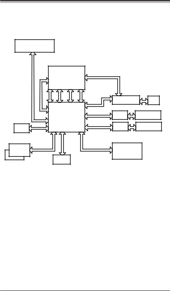
1-2 WPCM450 Block Diagram
The following diagram represents a typical system setup for the WPCM450 Controller.
PROCESSOR
|
|
South Bridge |
PCI-E |
|
|
|
||
CTRL |
|
|
|
|
|
|||
LPC |
PCI |
USB |
USB 2.0 |
|
Ethernet CTRL |
|
||
up- & |
|
|
||||||
|
|
|
1.1 |
|
|
|
|
RJ45 |
Wake |
|
|
|
|
RMII |
Onboard LAN1 |
||
|
|
|
|
|
||||
|
|
|
|
Serial Port |
|
Serial Port |
||
PECI |
|
WPCM450 |
RS232 |
|||||
|
|
|||||||
|
|
|
|
|
||||
VGA |
|
|
|
|
RMII |
PHY |
RJ45 |
|
|
|
|
|
|
|
Dedicated LAN |
||
Sensors |
|
|
|
|
SPI |
NOR Flash |
|
|
|
|
|
|
|
|
|||
|
|
DDR2 |
|
|
|
|
|
|
1-3 A Brief Introduction to the IPMI
The Intelligent Platform Management Interface (IPMI) Specification defines a set of common interfaces to a computer system that provides remote access to multiple users from different locations for networking. It also allows a system administrator to monitor system health and to manage computer events remotely.
IPMI operates independently of the operating system. When used in conjunction with the IPMIView, which is an IPMI-compliant management application software loaded into a PC, the WPCM450 BMC Controller provides serial link connections between the South Bridge and other onboard system components, allowing for network interfacing via remote access. With the WPCM450 Controller and the IPMIView software built in, the Supermicro motherboard allows an administrator to access, monitor, diagnose and manage a computer system from a remote site. It also provides remote access to multiple users from different locations for system maintenance and network management.
1-3


 Embedded BMC/IPMI User's Guide
1-4 Motherboards Supported
This version of Embedded BMC/IPMI is supported by the motherboards listed in the table below. If your motherboard is not included in the table, please refer to the motherboard product page on our web site @www.supermicro.com and download the right BMC/IPMI user's guide for your motherboard.
Intel UP Motherboards |
Intel DP Motherboards |
AMD Motherboards |
supported |
supported |
supported |
X7SB3-F |
X7DCT-3F |
H8DMT-F |
|
|
|
X8ST3-F |
X7DCT-3IBXF |
H8DMT-IBXF |
|
|
|
X8STi-F |
X7DCT-LF |
|
|
|
|
X8STi-3F |
X8DAH+-F |
|
|
|
|
|
X8DT3-F |
|
|
|
|
|
X8DT3-LN4F |
|
|
|
|
|
X8DTH-6F |
|
|
|
|
|
X8DTH-iF |
|
|
|
|
|
X8DTi-F |
|
|
|
|
|
X8DTi-LN4F |
|
|
|
|
|
X8DTT-F |
|
|
|
|
|
X8DTT-IBQF |
|
|
|
|
|
X8DTT-IBXF |
|
|
|
|
|
X8DTU-F |
|
|
|
|
1-5 An Important Note to the User
The graphics shown in this user's guide were based on the latest information available at the time of publishing of this guide. The IPMI screens shown on your computer may or may not look exactly like the screen shown in this user's guide.
1-4
Chapter 2: Configuring BMC/IPMI Settings
Chapter 2
Configuring the BMC IPMI Settings
With the Nuvoton WPCM450 BMC Controller chip built in, the Supermicro motherboard allows the user to access, monitor, manage and interface with systems in remote locations. The necessary utilities for accessing and configuring the IPMI settings are included on the bootable CDs that came with your motherboard. This section provides detailed information on how to configure the IPMI settings.
2-1 Configuring the IP/MAC Addresses
Note: The DHCP (Dynamic Host Configuration Protocol) is on by default. To change the manufacturer default setting, please use the ipmicfg utility or the BIOS firmware.
To Set the IP/MAC Addresses Using the IPMICFG Utility
1.Run the ipmicfg utility from the bootable CD that came with your shipment.
2.Follow the instructions given in the Readme.txt file to configure Gateway IP/ Netmask IP addresses, to enable/disable DHCP and to configure other IPMI settings.
IPMICFG Version 1.10 (Build 080711) Copyright 2008 Super Micro Computer, Inc. Usage: IPMICFG Parameters (Example: IPMICFG -m 192.168.1.123)
|
-m |
Shows IP and MAC |
|
|
|
|
|
|
-m IP |
Sets IP (format: ###.###.###.###) |
|
|
|
|
|
|
-a MAC |
Sets MAC (format: ##:##:##:##:##:##) |
|
|
-k |
Shows Subnet Mask |
|
|
|
|
|
|
-k Mask |
Sets Subnet Mask (format: ###.###.###.###) |
|
|
-dhcp |
Gets the DHCP status |
|
|
|
|
|
|
-dhcp on |
Enables the DHCP |
|
|
|
|
|
|
-dhcp off |
Disables the DHCP |
|
|
|
|
|
|
-g |
Shows Gateway IP |
|
|
|
|
|
|
-g IP |
Sets Gateway IP (format: ###.###.###.###) |
|
|
-r |
BMC color reset |
|
|
|
|
|
|
-garp on |
Enables the Gratuitous ARP |
|
|
-garp off |
Disables the Gratuitous ARP |
|
|
|
|
|
|
|
|
|
2-1


 Embedded BMC/IPMI User's Guide
-fd |
Resets to the factory defaults |
-ver |
Gets the firmware revision |
|
|
-vlan |
Gets VLAN status |
-vlan on (VLANtag) |
Enables the VLAN and sets the VLAN tag (If VLAN |
|
tag is not given, it uses previously saved value.) |
-vlan off |
Disables the VLAN |
|
|
-raw |
Sends a RAW IPMI request and print the re- |
|
sponse. Format: NetFn LUN Cmd [Data1...Data] |
To set the IP/MAC Addresses Using the AMI BIOS Settings
1.Go to the AMIBIOS utility by pressing <Del> at bootup.
2.Select IPMI from the Advanced Menu.
3.Select LAN Configuration from the IPMI submenu.
4.Click <IP Address Source>. Select Static and press <Enter>. The onboard BIOS utility will automatically set the IP Address, MAC Address, Gateway, and Subnet Mask.
5.Once the IP, MAC Addresses, Gateway and Subnet Mask are set, click <Update LAN Settings>. Select Yes and press <Enter> to update the IPMI LAN settings.
6.Go to the Exit menu. Select Save Changes & Exit and press <Enter> to save changes and exit the BIOS.
Accessing the BMC
1.Connect a LAN cable to the onboard LAN1 port or the dedicated IPMI LAN port.
2.Choose a computer connected to the same network and open the IPMIView utility.
3.Go to File>New>System. Enter System Name, IP Address of LAN1 or the dedicated LAN, Description in the appropriate fields and press <Enter>.
4.Select the system from the IPMI Domain. Enter the Login ID and Password in the appropriate fields to login to the IPMIView utility.
2-2

Chapter 2: Configuring BMC/IPMI Settings
Using the Internet Browser
1.Connect a LAN cable to the onboard LAN1 port or the dedicated IPMI LAN port.
2.Choose a computer that is connected to the same network and open the browser.
3.Enter the IP address of each server that you want to connect to in the address bar in your browser.
4.Once your machine is connected to the remote server, the Log-In screen as shown on the next page will display.
 Notes:
1.If you wish to use the IPMI-dedicated LAN port for your network connections, be sure to connect an RJ45 cable to your dedicated LAN port before you activate the BMC (at first power-on or cold reset). Otherwise, the BMC will look for a shared LAN port to connect to if the IPMI-dedicated LAN cable is not detected upon BMC activation.
2.However, if you should decide to use the IPMI-dedicated LAN port for a network connection, please perform a BMC cold reset or power cycle reset for the dedicated LAN to be detected.
2-3


 Embedded BMC/IPMI User's Guide
2-2 Using IE* to Access the BMC/IPMI Settings from Your Computer
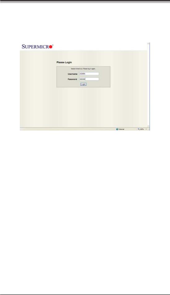
2.2.1 To Log In
Once you are connected to the remote server, the following screen will display.
1.Enter your Username.
2.Enter your Password and click <Login>.
3.The Home Page will display on the next page.
 Note 1: To use the IPMIView Utility to access BMC/IPMI settings, refer to the IPMIView User's Guide for instructions.
Note 2: The manufacturer default username and password are ADMIN. Once you have logged into the BMC using the manufacturer default password, be sure to change your password for system security.
2-4

Chapter 2: Configuring BMC/IPMI Settings
2.2.2 IPMI Main Page
Once you are logged into the IPMI utility, the IPMI Main page will display.
1
2
3
The IPMI screen contains the following three sections:
•The Submenu Bar (Top)
•The Options Window (Left)
•The Main Display area (Center)
1. Submenu Bar
The submenu bar on the top lists the following submenus:
|
Submenu Bar |
System Information |
This submenu displays system information. |
Server Health |
This submenu displays server health monitoring status. |
Configuration |
This submenu allows the user to configure the IPMI settings. |
Remote Control |
This submenu allows the user to launch KVM Console and perform |
|
power control & management. |
Maintenance |
This submenu allows the user to update the firmware and reset the unit. |
Miscellaneous |
This submenu allows the user to post snooping codes and to launch the |
|
SOL console. |
Language |
This submenu allows the user to select a language setting. (Currently, |
|
only English is available.) |
? Help |
Click this item to find an answer when you have a question. |
2-5


 Embedded BMC/IPMI User's Guide
2. The Options window
The Options window on the left side allows the user to quickly navigate through different submenu options.
|
Options window |
Submenu Name |
Click this item to display and configure a submenu items. |
(System Information) |
|
Refresh Page |
Click this icon to refresh the page. |
Logout |
Click this icon to logout from the IPMI utility. |
3. The Main Display Area
This area displays the items included in a submenu.
The following items are included in the System Information submenu.
•Firmware Revision: This item displays the current firmware revision number.
•Firmware Build Time: This item displays the time and the date when this version of firmware was built.
•System MAC Address 1: This item displays the MAC address of the first system that is connected to IPMI.
•System MAC Address 2: This item displays the MAC address of the second system that is connected to IPMI.
2-6

Chapter 2: Configuring BMC/IPMI Settings
2.3 Server Health
This feature allows the user to set Server Health Settings. Click <Server Health> to display the following submenu.
The Server Health submenu contains the following items.
• Sensor Readings
•
•
Sensor Readings with Thresholds
Event Log
2.3.1. Sensor Readings
Click this item to display the Sensor Reading page as shown below.
2-7


 Embedded BMC/IPMI User's Guide
•All Sensors: This item displays the readings for all sensors
•Temperature Sensors: This item displays the system temperature.
•Voltage Sensors: This item displays the following items: CPU Vcore, CPU DIMM voltages, +3.3V, +3.3VSB, +1.5V, +12V, +5V and VBAT (Battery Voltage).
•Fan Sensors: This item displays the readings of the onboard fans.
•Power Supply: This item displays the status of power supply failure monitoring.
•OEM Reserved: This item reserved for OEM use.
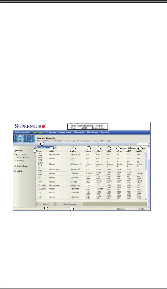
2.3.2. Sensor Readings with Thresholds
Click this item to display all sensor readings and their thresholds as shown below.
|
1 |
|
|
|
|
|
|
|
2 |
3 |
4 |
5 |
6 |
7 |
8 |
9 |
10 |
|
|
|
|
|
|
|
|
1112
1.From the pull-down menu select a sensor you want to display its readings
and thresholds.
2.Name: This item displays the name of the item being monitored.
3.Status: This item displays the status of the sensor item.
4.Reading: This item displays the reading of the sensor.
5.Low NR (Low Non-Recoverable): This is the low threshold of a non-recover- able item. Any item with a reading below this point will not be recovered.
2-8
Chapter 2: Configuring BMC/IPMI Settings
6.Low CT (Low Critical-Threshold): This is the low threshold of a critical item. Any item with a reading below this threshold is in a critical state.
7.Low NC (Low Non-Critical): This is the low threshold of a non-critical item. Any item with a reading above this threshold is not in a critical state.
8.High NC (High Non-Critical): This is the high threshold of a non-critical item. Any item with a reading below this threshold is not in a critical state.
9.High CT (High Critical-Threshold): This is the high threshold of a critical item. Any item with a reading above this threshold is in a critical state.
10.High NR (High Non-Recoverable): This is the high threshold of a non-recover- able item. Any item with a reading above this point will not be recovered.
11.Refresh: Click this tab to refresh this page.
12.Hide/(Show) Thresholds: Click this tab to hide/(or to show) the thresholds of the items.
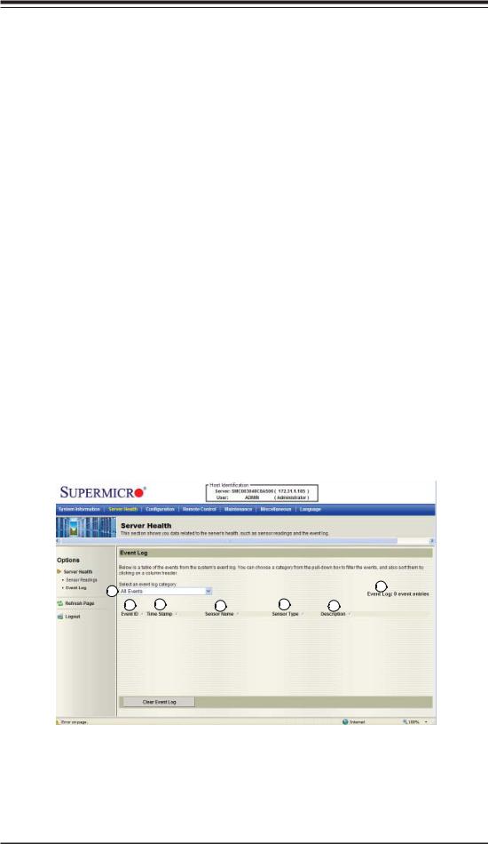
2.3.3. Event Log
This feature allows the user to configure Event Log settings. When you select Event Log in Options Window the following page will display.
1 |
|
|
|
7 |
|
|
|
|
|
2 |
3 |
4 |
5 |
6 |
1.From the pull-down menu select an event category to show the vent log, which includes the following categories: All Events, Sensor-Specific Events, BIOS-Generated Events, and System-Management Software Events.
2.Event ID: This item displays the event ID of this event.
2-9
 Loading...