


 Loading...
SuperServer®
E300-9D-4CN8TP
E300-9D-8CN8TP
USER’S MANUAL
Revision 1.0

The information in this User’s Manual has been carefully reviewed and is believed to be accurate. The vendor assumes no responsibility for any inaccuracies that may be contained in this document, and makes no commitment to update or to keep current the information in this manual, or to notify any person or organization of the updates. Please Note:
For the most up-to-date version of this manual, please see our website at www.supermicro.com.
Super Micro Computer, Inc. ("Supermicro") reserves the right to make changes to the product described in this manual at any time and without notice. This product, including software and documentation, is the property of Supermicro and/ or its licensors, and is supplied only under a license. Any use or reproduction of this product is not allowed, except as expressly permitted by the terms of said license.
IN NO EVENT WILL Super Micro Computer, Inc. BE LIABLE FOR DIRECT, INDIRECT, SPECIAL, INCIDENTAL, SPECULATIVE OR CONSEQUENTIAL DAMAGES ARISING FROM THE USE OR INABILITY TO USE THIS PRODUCT OR DOCUMENTATION, EVEN IF ADVISED OF THE POSSIBILITY OF SUCH DAMAGES. IN PARTICULAR, SUPER MICRO COMPUTER, INC. SHALL NOT HAVE LIABILITY FOR ANY HARDWARE, SOFTWARE, OR DATA STORED OR USED WITH THE PRODUCT, INCLUDING THE COSTS OF REPAIRING, REPLACING, INTEGRATING, INSTALLING OR RECOVERING SUCH HARDWARE, SOFTWARE, OR DATA.
Any disputes arising between manufacturer and customer shall be governed by the laws of Santa Clara County in the State of California, USA. The State of California, County of Santa Clara shall be the exclusive venue for the resolution of any such disputes. Supermicro's total liability for all claims will not exceed the price paid for the hardware product.
FCC Statement: This equipment has been tested and found to comply with the limits for a Class B digital device pursuant to Part 15 of the FCC Rules. These limits are designed to provide reasonable protection against harmful interference when the equipment is operated in a commercial environment. This equipment generates, uses, and can radiate radio frequency energy and, if not installed and used in accordance with the manufacturer’s instruction manual, may cause harmful interference with radio communications. Operation of this equipment in a residential area is likely to cause harmful interference, in which case you will be required to correct the interference at your own expense.
California Best Management Practices Regulations for Perchlorate Materials: This Perchlorate warning applies only to products containing CR (Manganese Dioxide) Lithium coin cells. “Perchlorate Material-special handling may apply. See www.dtsc.ca.gov/hazardouswaste/perchlorate”.
WARNING: This product can expose you to chemicals including
!lead, known to the State of California to cause cancer and birth defects or other reproductive harm. For more information, go to www.P65Warnings.ca.gov.
The products sold by Supermicro are not intended for and will not be used in life support systems, medical equipment, nuclear facilities or systems, aircraft, aircraft devices, aircraft/emergency communication devices or other critical systems whose failure to perform be reasonably expected to result in significant injury or loss of life or catastrophic property damage. Accordingly, Supermicro disclaims any and all liability, and should buyer use or sell such products for use in such ultra-hazardous applications, it does so entirely at its own risk. Furthermore, buyer agrees to fully indemnify, defend and hold Supermicro harmless for and against any and all claims, demands, actions, litigation, and proceedings of any kind arising out of or related to such ultra-hazardous use or sale.
Manual Revision 1.0
Release Date: December 26, 2018
Unless you request and receive written permission from Super Micro Computer, Inc., you may not copy any part of this document. Information in this document is subject to change without notice. Other products and companies referred to herein are trademarks or registered trademarks of their respective companies or mark holders.
Copyright © 2018 by Super Micro Computer, Inc.
All rights reserved.
Printed in the United States of America
2
Preface
Preface
About this Manual
This manual is written for professional system integrators and PC technicians. It provides information for the installation and use of the SuperServer E300-9D-4CN8TP/E300-9D-8CN8TP. Installation and maintenance should be performed by experienced technicians only.
Notes
For your system to work properly, please follow the links below to download all necessary drivers/utilities and the user’s manual for your server.
•Supermicro product manuals: http://www.supermicro.com/support/manuals/
•Product drivers and utilities: https://www.supermicro.com/wftp/driver
•Product safety info: http://www.supermicro.com/about/policies/safety_information.cfm
If you have any questions, please contact our support team at: support@supermicro.com
This manual may be periodically updated without notice. Please check the Supermicro website (http://www.supermicro.com) for possible updates to the manual revision level.
Warnings
Special attention should be given to the following symbols used in this manual.
Warning! Indicates important information given to prevent equipment/property damage or personal injury.
 Warning! Indicates high voltage may be encountered when performing a procedure.
3

SuperServer E300-9D-4CN8TP/E300-9D-8CN8TP User's Manual
|
Contents |
|
Chapter 1 Introduction |
|
|
1.1 |
Overview............................................................................................................................... |
7 |
1.2 |
System Features................................................................................................................... |
8 |
1.3 |
Chassis Features.................................................................................................................. |
9 |
|
Front Features..................................................................................................................... |
9 |
|
Rear Features.................................................................................................................... |
10 |
1.4 |
Motherboard Layout............................................................................................................ |
11 |
|
Quick Reference Table...................................................................................................... |
12 |
|
Chipset Block Diagram...................................................................................................... |
14 |
1-5 Server Installation and Setup.............................................................................................. |
15 |
|
|
Unpacking the System....................................................................................................... |
15 |
|
Warnings and Precautions................................................................................................. |
15 |
|
Adding Components to your System................................................................................. |
15 |
|
Installing Rack Mounting Brackets.................................................................................... |
16 |
Chapter 2 Maintenance and Component Installation |
|
|
2.1 |
Removing Power................................................................................................................. |
17 |
2.2 |
Accessing the System......................................................................................................... |
18 |
2.3 |
Motherboard Components.................................................................................................. |
19 |
|
Processor........................................................................................................................... |
19 |
|
Memory Support................................................................................................................ |
19 |
|
Installing Memory............................................................................................................... |
20 |
|
Solid State Storage ........................................................................................................... |
21 |
|
Motherboard Battery.......................................................................................................... |
22 |
2.4 |
Chassis Components.......................................................................................................... |
23 |
|
Installing the Storage Drive .............................................................................................. |
23 |
|
Installing the Riser Card ................................................................................................... |
24 |
|
System Cooling.................................................................................................................. |
25 |
Chapter 3 Motherboard Connections |
|
|
3.1 |
Power Connections............................................................................................................. |
26 |
3.2 |
Headers and Connectors.................................................................................................... |
27 |
3.3 |
Ports.................................................................................................................................... |
32 |
3.4 |
Front Control Panel............................................................................................................. |
34 |
3.5 |
Jumpers.............................................................................................................................. |
37 |
4

Preface
|
Explanation of Jumpers..................................................................................................... |
37 |
3.6 |
LED Indicators.................................................................................................................... |
40 |
Chapter 4 Software |
|
|
4.1 |
Microsoft Windows OS Installation..................................................................................... |
41 |
4.2 |
Driver Installation................................................................................................................ |
43 |
4.3 |
SuperDoctor® 5................................................................................................................... |
44 |
4.4 |
IPMI..................................................................................................................................... |
45 |
Chapter 5 UEFI BIOS |
|
|
5.1 |
Introduction......................................................................................................................... |
46 |
|
Starting the Setup Utility.................................................................................................... |
46 |
5.2 |
Main Setup.......................................................................................................................... |
47 |
5.3 |
Advanced............................................................................................................................ |
49 |
5.4 |
Event Logs.......................................................................................................................... |
77 |
5.5 |
IPMI..................................................................................................................................... |
79 |
5.6 |
Security............................................................................................................................... |
83 |
5.7 |
Boot..................................................................................................................................... |
88 |
5.8 |
Save & Exit......................................................................................................................... |
90 |
Appendix A BIOS Error Codes
Appendix B Standardized Warning Statements for DC Systems
Appendix C System Specifications
Appendix D UEFI BIOS Recovery
5

SuperServer E300-9D-4CN8TP/E300-9D-8CN8TP User's Manual
Contacting Supermicro
Headquarters |
|
Address: |
Super Micro Computer, Inc. |
|
980 Rock Ave. |
|
San Jose, CA 95131 U.S.A. |
Tel: |
+1 (408) 503-8000 |
Fax: |
+1 (408) 503-8008 |
Email: |
marketing@supermicro.com (General Information) |
|
support@supermicro.com (Technical Support) |
Website: |
www.supermicro.com |
Europe |
|
Address: |
Super Micro Computer B.V. |
|
Het Sterrenbeeld 28, 5215 ML |
|
's-Hertogenbosch, The Netherlands |
Tel: |
+31 (0) 73-6400390 |
Fax: |
+31 (0) 73-6416525 |
Email: |
sales@supermicro.nl (General Information) |
|
support@supermicro.nl (Technical Support) |
|
rma@supermicro.nl (Customer Support) |
Website: |
www.supermicro.nl |
Asia-Pacific |
|
Address: |
Super Micro Computer, Inc. |
|
3F, No. 150, Jian 1st Rd. |
|
Zhonghe Dist., New Taipei City 235 |
|
Taiwan (R.O.C) |
Tel: |
+886-(2) 8226-3990 |
Fax: |
+886-(2) 8226-3992 |
Email: |
support@supermicro.com.tw |
Website: |
www.supermicro.com.tw |
6
Chapter 1: Introduction
Chapter 1
Introduction
1.1 Overview
The SuperServer E300-9D-4CN8TP/E300-9D-8CN8TP is a compact, embedded system comprised of the SCE300 chassis and the X11SDV-4C-TP8F/8C-TP8F single processor motherboard. Refer to our website for information on operating systems that have been certified for use with the system (www.supermicro.com).
This chapter provides a brief outline of the functions and features. In addition to the motherboard and chassis, several important parts that are included with the system are listed below.
Main Parts List
Description |
Part Number |
Quantity |
|
150W DC power adapter |
MCP-250-10128-0N |
1 |
|
Fans |
FAN-0100L4 |
|
|
3 |
|||
RSC-RR1U-E8 Riser Card (Optional) |
RSC-RR1U-E8 |
1 |
|
Rackmount Rail Kit |
MCP-290-30002-0B |
1 set |
|
RJ45 SerialCable for Console |
CBL-CUSB-0975 |
|
|
1 |
|||
|
|
|
7
SuperServer E300-9D-4CN8TP/E300-9D-8CN8TP User's Manual
1.2 System Features
The following table provides an overview of the main features of the E300-9D-4CN8TP/E300-9D-8CN8TP server. Please refer to Appendix C for additional specifications.
System Features
Motherboard
X11SDV-4C-TP8F/8C-TP8F
Chassis
Compact Embedded Mini ITX Box, SCE300
CPU
Intel® Xeon® D-2123IT, 4-core/D-2146NT, 8-core (System on a Chip)
Memory
Supports up to 512GB of DDR4-2666/2400/2133 ECC LRDIMM or up to 256GB of DDR4-2666/2400/2133 ECC/ non-ECC RDIMM memory in four DIMM slots
Expansion Slots
One PCI-E 3.0 x8 slot One M.2 PCI-E 3.0 x4 slot One M.2 PCI-E 3.0 x2 slot
Storage Drives
Single fixed 2.5" hard drive bay with bracket (when AOC area is not occupied)
Power
150 watt DC power adapter
Cooling
Three 4-cm PWM chassis fans, plus one passive CPU heatsink
Dimensions
W x H x D: 10" (254 mm) x 1.7" (43 mm) x 8.9" (226 mm)
8
Chapter 1: Introduction
1.3 Chassis Features
The SCE300 is a compact embedded chassis that houses a Flex ATX form factor motherboard.
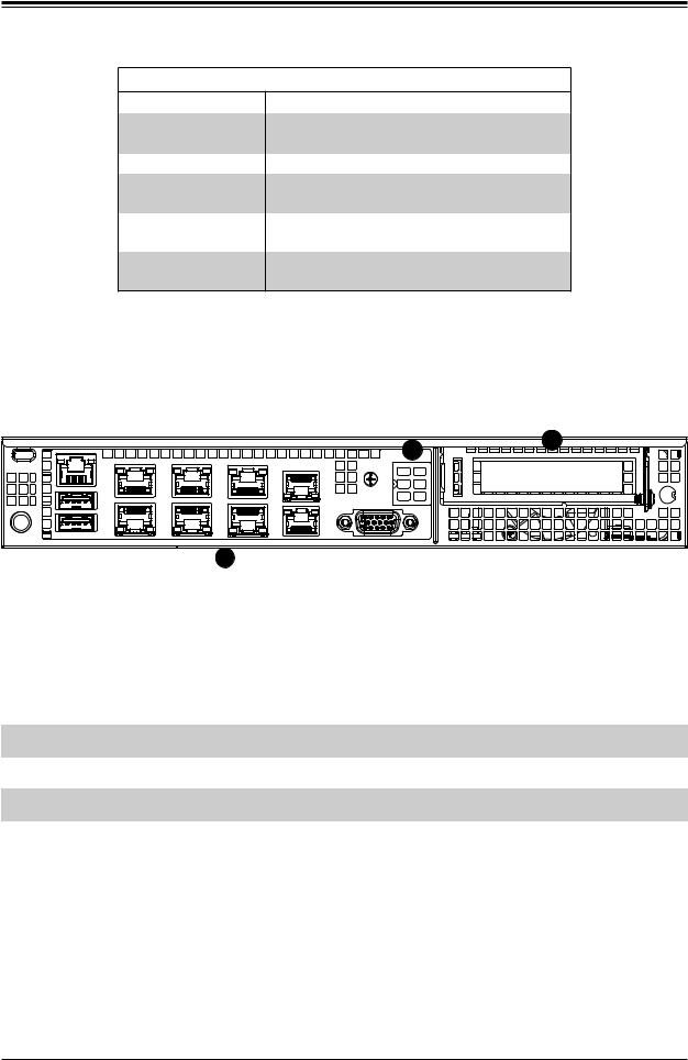
Front Features
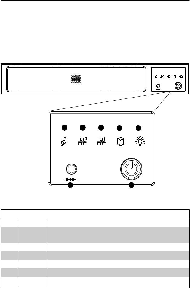
The control panel for the system is located on front of the chassis.
3 |
4 |
5 |
6 |
7 |
2 |
1 |
Figure 1-1. Chassis Front and Control Panel
Control Panel Features
Item Features Description
The main power switch applies or removes primary power from the power supply 1 Power button to the server but maintains standby power. To perform most maintenance tasks,
unplug the system to remove all power.
2Reset button
3Information LED
4and 5 NIC LED
6HDD LED
7Power LED
Resets the system.
Alerts operator to several states, as noted in the table below.
Indicates network activity on the LAN when flashing.
Indicates hard disk drive activity when flashing.
Indicates power is being supplied to the system power supply units. This LED is illuminated when the system is operating normally.
9
SuperServer E300-9D-4CN8TP/E300-9D-8CN8TP User's Manual
Information LED
Status
Continuously on and red
Blinking red (1Hz)
Blinking red (0.25Hz)
Solid blue
Blinking blue
Description
An overheat condition has occurred.
(This may be caused by cable congestion.) Fan failure, check for an inoperative fan.
Power failure, check for a non-operational power supply.
UID has been activated locally to locate the server in a rack environment.
UID has been activated using IPMI to locate the server in a rack environment.
Rear Features
The chassis rear holds input/output ports, described in Chapter 3.
2 |
3 |
|
|
1 |
|
Figure 1-2. Rear Chassis View
|
|
Rear Chassis Features |
|
|
|
|
|
Item |
Features |
Description |
|
|
|
|
|
1 |
I/O Ports |
IPMI LAN, USB, LAN, VGA (further described in Chapter 3) |
|
2 |
AOM Window |
Reserved for RJ45 console redirection cable |
|
3 |
PCI Bay |
Bay for low-profile PCI-E add-on card |
|
|
|
|
10
Chapter 1: Introduction
1.4 Motherboard Layout
Below is a layout of the X11SDV-4C-TP8F/8C-TP8F with jumper, connector and LED locations shown. See the table on the following page for descriptions. For detailed descriptions, pin-out information and jumper settings, refer to Chapter 4.
|
|
|
|
JMD1_SRW1 |
|
|
|
|
|
|
||
|
LEDM1 |
|
|
|
|
|
|
|
|
|||
|
SLOT6 |
LEDT2 LEDT3 |
|
|
|
|
|
|
||||
|
JIPMB1 |
|
LAN3/4 |
|
|
|
||||||
|
LEDT4 |
|
|
|
|
|||||||
JPG1 |
SLOT7 |
|
|
|
|
|
|
|||||
|
|
|
|
|
|
|||||||
JMD1 |
|
LED3 |
LEDT1 |
|
|
|
LAN1/2 |
|||||
|
LED2 |
|
|
|
|
|
|
|
|
|||
|
|
|
UID VGA |
LAN7/8 |
LAN5/6 |
|
|
IPMI |
||||
|
|
|
|
|
|
|
|
|
USB4/5 (3.0) |
|||
|
|
|
|
|
|
|
|
|
|
|
|
|
|
|
|
|
|
|
|
|
|
|
|
|
|
|
|
|
|
|
|
|
|
|
|
|
|
|
|
|
|
|
|
|
|
|
|
|
|
|
|
JPB1:(debug only)  1-2:ENABLE
 2-3:DISABLE
JMP1_SRW2 |
|
|
JMP1_SRW1 |
|
1 |
JSMB1 |
1 |
JSMB1JI2C1 |
JI2C1 |
||
JWD1 |
|
|
JI2C2 |
|
JI2C2 |
JPUSB1 |
|
|
JPME2 |
||
|
|
HC-2.JMD1:M / X4 0.3 E-PCI |
|
|
|
2 |
-S |
|
|
|
SATA5 |
|
|
|
SRW1 JMP1 |
|
|
|
SRW2 JMP1 |
|
|
||
|
||
LEDM1
JPG1 


JWD1


JPUSB1


|
1 |
JMP1 PCI-E 3.0 X1 |
JPME2 |
|
|
|
|
|
JMP1 |
|
|
JL1 |
JL1 |
JMD2_SRW1 |
JMD2_SRW1 |
|
|
|
USB 0/1 |
|
USB0/1
|
|
A |
A |
|
|
|
PRESS FIT |
|
|
|
|
|
JPL1: |
|
|
|
|
|
|
|
|
|
|
|
|
1 2 |
|
|
|
|
|
|
|
|
|
|
|
|
|
|
LAN1/2/3/4 2:ENABLE |
|
|
LED3 |
LED2 |
UID |
|
|
|
|
|
|
|
|
- - |
|
|
|
|
|
|
|
|
|
|
3:DISABLE |
|||
|
|
C |
C |
|
|
|
|
|
|
|
|
|
|
|
|
|
|
|
VGA |
|
|
|
|
|
|
|
|
|
|
|
|
|
JMD1 |
|
|
|
|
|
|
|
JPL1 |
|
|
|
|
|
_ |
|
|
|
|
|
|
|
JPL1 |
|
|
|
|
|
SRW1 |
|
|
|
|
LAN 3/4 |
LAN 1/2 |
IPMI_LAN |
|
|
|
|
|
|
|
|
|
|
|
|
|
USB 4/5 (3.0) |
|
CPU |
|
CPU |
|
|
LEDT4 |
|
LEDT1 C |
LAN 5/6 |
|
|
|
||
|
|
|
|
|
|
A |
A |
|
|
|
|
|
|
|
|
|
|
|
|
C |
|
|
|
|
|
|
|
E-PCISLOT6 |
|
E-PCISLOT7 |
|
|
LEDT2 |
A |
A |
|
LEDT3 |
|
|
JPI2C1 |
JPI2C1 |
|
|
|
C |
LAN 7/8 |
C |
|
|
||||||
|
|
|
|
|
|
|
SFP1 |
|
|
|
|
|
|
X16 0.3 |
JIPMB1 |
X8 0.3 |
|
|
|
|
|
|
|
|
|
JPV1 |
JPV1 |
SGPIO1-S JLANLED1 |
|
|
|
|
|
|
|
|
|
|
|
||
JTGLED1 |
|
JNVI2C1 |
|
|
|
|
|
CPU |
|
|
JLANLED1 |
||
|
|
|
|
|
|
|
|
S-SGPIO1 |
|||||
|
|
|
|
|
|
|
|
|
|
|
|
|
JNVI2C1 |
|
|
|
|
|
|
|
|
|
|
|
|
|
JTGLED1 |
JSIM1
USB2/3
JMD2
JTGLED2
S-SATA3 S-SATA2 S-SATA1 S-SATA0
JSTBY1
USB 2/3 |
G4 |
G1 |
|
S1 |
S3 |
JSIM1 |
|
S2 |
S5 |
||
|
S4 |
S6 |
|
|
G3 |
G2 |
|
|
|
|
JMD2 |
M.2-H |
|
|
|
|
|
|
|
|
|
|
|
|
PCI-E 3.0 X2/S-SATA42 |
|
|
|
|
|
|
|
|
|
|||
|
|
|
|
|
|
|
|
JBT1 |
|
|
|
|
|
|
JTGLED2 |
|
|
|
|
|
|
COM1 |
JGP1 |
|
|
|
|
||
SATA0-S |
|
SATA1-S |
SATA2-S |
-S |
JTPM1 |
|
|
|
|
|
||||
|
|
|
JF1 |
|
|
BAR CODE |
|
|||||||
DOM:SUPER |
|
|
|
|
|
DIMME1 |
BT1 |
|||||||
SATA3 |
|
|
|
|
|
|
|
|
||||||
JSTBY1 |
JNS1 |
|
|
|
|
|
|
|
|
|
DIMMD1 |
|
|
|
|
|
|
ON RST X FF |
NIC2 |
NIC1 LED LED |
C A |
|
X11SDV-8C-TP8F |
||||||
|
|
|
|
|
PWR |
OH |
JF1: |
HDD PWR |
|
|
|
|
|
|
|
|
|
|
|
|
|
|
|
|
REV:1.02 |
MADE IN USA |
|||
|
|
|
I-SATA0-3 |
|
I- |
SATA4-7 |
|
|
16 |
|
||||
|
|
|
PRESS FIT |
|
|
PRESS FIT |
|
|
|
|
|
|||
|
JD1 |
|
FANB |
|
|
|
|
|
LED1 |
|
|
|
||
JSD1 |
|
|
|
|
|
|
FANA |
:LEDPWR |
|
|
|
|
||
LED 3:PWR-1 7:SPEAKER-4 |
|
|
|
|
|
|
|
|
|
FAN4 |
FAN3 |
|||
JPW1 |
JPW1 |
|
DIMME1 |
||
|
||
|
DIMMD1 |
|
DIMMB1 DIMMA1 |
DIMMB1 |
|
DIMMA1 |
||
|
||
JPH1 FAN2 FAN1 |
|
|
|
FAN1 |
|
|
|
|
|
|
JF1 |
|
|
BT1 |
|
|
|
|
|
|
|
|
|
|
|
|
|
|
|
|
|
|||
|
|
|
|
|
|
|
|
|
|
FAN2 |
||||
JSD1 |
|
|
|
|
|
LED1 |
JBT1 |
FAN4 |
|
|
JPH1 |
|||
|
FAN3 |
|||||||||||||
JD1 |
|
|
FANA |
|
|
|
|
|
||||||
|
|
JGP1 |
|
|
|
|
|
|
|
|
||||
JNS1 |
|
|
|
|
|
|
|
|
|
|
||||
|
|
COM1 |
|
|
|
|
|
|
|
|
||||
FANB |
|
I |
-SATA4-7 |
|
|
|
|
|
|
|
|
|||
|
|
I-SATA0 |
-3 |
|
|
|
|
|
|
|
|
|||
|
|
|
JTPM1 |
|
|
|
|
|
|
|
|
|||
Figure 1-3. Motherboard Layout
Notes:
•" " indicates the location of pin 1.
•Jumpers/LED indicators not indicated are used for testing only.
•The X11SDV-4C-TP8F has the same layout as the X11SDV-8C-TP8F (pictured) but features a different embedded processor.
11
SuperServer E300-9D-4CN8TP/E300-9D-8CN8TP User's Manual
Quick Reference Table
Jumper |
Description |
Default Setting |
|
JBT1 |
CMOS Clear |
Open: Normal, Closed: Clear CMOS |
|
JI2C1, JI2C2 |
SMB to PCI-E Slots Enable/Disable |
Pins 2-3 (Disabled) |
|
JNS1 |
Mini-SAS HDD NVMe/SATA Mode Select |
Pins 1-2: SATA (Default), Pins 2-3: NVMe |
|
JPG1 |
Onboard VGA Enable |
Pins 1-2 (Enabled) |
|
JPL1 |
LAN1/2/3/4 Enable |
Pins 1-2 |
(Enabled) |
JPME2 |
Manufacturing Mode Select |
Pins 1-2 |
(Normal) |
JPUSB1 |
USB Wake Up |
Pins 1-2 |
(Enabled) |
JWD1 |
Watch Dog |
Pins 1-2 |
(Reset) |
LED |
Description |
Status |
|
LED1 |
Power LED |
Solid Green: Power On |
|
LED2 |
UID LED |
Solid Blue: Unit Identified |
|
LED3 |
Overheat/PWR Fail/Fan Fail |
Solid Red: Overheat |
|
Blinking Red: PWR Fail or Fan Fail |
|||
|
|
||
LEDM1 |
BMC Heartbeat |
Blinking Green: BMC Normal |
Connector |
Description |
|
BT1 |
Onboard Battery |
|
COM1 |
COM Header |
|
FAN1 - FAN4, FANA, FANB |
System/CPU Fan Headers |
|
IPMI_LAN |
Dedicated IPMI LAN Port |
|
I-SATA0-3, I-SATA4-7 |
Eight Intel® PCH SATA 3.0 Ports or Two NVMe U.2 Ports |
|
(See jumper JNS1 setting) |
||
|
||
JD1 |
PWR LED/Buzzer Header (Pins 1-4: PWR LED, Pins 5-7: Buzzer) |
|
JF1 |
Front Control Panel Header |
|
JGP1 |
General Purpose I/O Header |
|
JIPMB1 |
System Management Bus Header (for IPMI only) |
|
JL1 |
Chassis Intrusion Header |
|
JLANLED1 |
LAN1 - LAN4 Activity LED Header |
|
JMD1 |
M.2 PCI-E 3.0 x4/S-SATA5 Connector (M-Key 2280) |
|
JMD2 |
M.2 PCI-E 3.0 x2/S-SATA4 Connector (B-Key 3042) |
|
JMD1_SRW1, JMD2_SRW1 |
M.2 Holding Screws |
|
JMP1 |
Mini PCI-E x1 Connector |
|
JMP1_SRW1 |
Mini PCI-E x1 Connector Holding Screw |
|
JNVI2C1 |
NVMe I2C Header |
|
JPI2C1 |
Power I2C System Management Bus (Power SMB) Header |
|
JPH1 |
4-pin Power Connector for HDD use |
12
Chapter 1: Introduction
Connector
JPW1
JPV1
JSD1
JSIM1
JSMB1
JSTBY1
JTGLED1
JTGLED2
JTPM1
LAN1 - LAN4
LAN5 - LAN6
LAN7 - LAN8 S-SATA0 - S-SATA3
S-SGPIO1
SLOT6
SLOT7
UID
USB0/1, USB2/3
USB4/5
VGA
Description
24-pin ATX Main Power Connector
12V 8-pin DC Power Connector (Required to provide extra power to CPU, or as alternative power for special enclosure when the 24 pin ATX power is not in use)
SATA Disk On Module (DOM) Power Connector
Nano SIM Slot for M.2 B-Key WAN card support
System Management Bus Header
+5V Standby Power Header
LAN7/LAN8 Activity LED Header
LAN5/LAN6 Activity LED Header
Trusted Platform Module (TPM)/Port 80 Connector
1GbE (RJ45) LAN Ports
10GbE (RJ45) LAN Ports
10G SFP+ LAN Ports
SATA 3.0 Ports
Serial General Purpose I/O Header for S-SATA0-3
CPU PCI-E 3.0 x16 Slot
CPU PCI-E 3.0 x8 Slot
Unit Identifier Button
Front Accessible USB 2.0 Headers
Back Panel USB 3.0 Ports
VGA Port
13
SuperServer E300-9D-4CN8TP/E300-9D-8CN8TP User's Manual
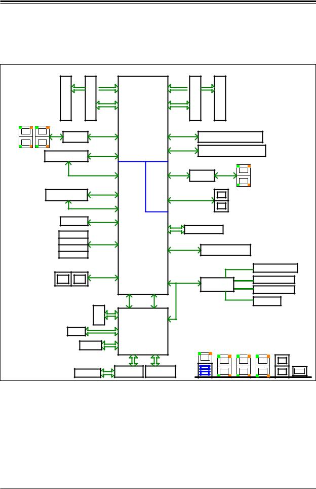
Chipset Block Diagram
|
DDR4 1866/2133/2400 |
|
|
|
|
DDR4 1866/2133/2400 |
|
|
||||
|
E1 |
E |
D1 |
|
U1 |
|
|
A1 |
B |
B1 |
|
|
|
DIMM |
|
DIMM |
D |
SoC |
A |
DIMM |
|
DIMM |
|
|
|
|
DDR4 |
|
DDR4 |
CPU |
DDR4 |
|
DDR4 |
|
|
|||
|
|
|
|
|
|
|
||||||
JLAN2 |
JLAN1 |
|
|
|
|
|
|
|
|
|
|
|
|
I350 AM4 |
PCIE 3.0 x4 |
PE2[15:12] |
PE2[7:0] |
PCIE 3.0 x8 |
JPCIE1 SLOT7 PCIE 3.0 x8 |
|
|||||
|
|
|
|
|
|
|||||||
|
|
|
|
|
|
|
|
|||||
|
|
|
|
|
|
PE1[15:0] |
PCIE 3.0 x16 |
JPCIE2 SLOT6 PCIE 3.0 x16 |
|
|||
|
|
|
PCIE 3.0 x4 |
|
|
|
|
|||||
|
M.2(M-key)CONN |
PE2[11:8] |
|
|
|
|
||||||
|
|
|
|
|
|
|
|
|
|
|||
|
|
|
|
|
|
|
|
JLAN3 |
|
|
||
|
|
|
|
|
PCH |
10G PHY |
|
|
|
|
|
|
|
|
|
SATA3.0#5 |
|
|
|
|
|
|
|||
|
|
|
Flexible I/O |
KR |
|
X557-AT2 |
|
|
|
|||
|
|
|
|
|
|
|
|
|
||||
|
|
|
|
|
17 |
|
|
|
|
|
|
|
|
|
|
PCIE 3.0 x2 |
|
|
|
|
|
SFP+ |
|
|
|
|
M.2(B-key)CONN |
Flexible I/O |
|
|
|
|
|
|
|
|||
|
|
|
|
|
|
|
|
|
|
|||
|
|
|
|
|
8,9 |
SFI |
|
|
|
|
|
|
|
|
|
SATA3.0#4 |
|
|
|
|
|
|
|
||
|
|
|
Flexible I/O |
|
|
|
|
|
|
|
||
|
|
|
|
|
|
|
|
|
|
|
|
|
|
|
|
|
|
16 |
|
|
|
|
|
|
|
|
miniPCIe |
PCIE 3.0 x1 |
Flexible I/O |
|
SPI |
|
|
|
|
|
||
|
|
|
|
|
|
|
|
|
||||
|
|
|
|
|
11 |
|
JTPM1 Header |
|
|
|||
|
SATA3.0#3 |
|
|
|
|
|
|
|
||||
|
|
|
|
|
|
|
|
|
|
|
||
|
SATA3.0#2 |
SATA3.0 |
Flexible I/O |
|
USB 3.0/2.0 |
|
|
|
|
|||
|
SATA3.0#1 |
|
|
12~15 |
Flexible I/O |
USB 3.0 Rear I/O |
|
|
||||
|
|
|
|
6,7 |
|
|
|
|
||||
|
SATA3.0#0 |
|
|
|
|
|
|
|
|
|||
|
|
|
|
|
|
|
|
|
|
|
||
|
MINI-SAS HD / U.2 |
PCIE 3.0 x8 / |
|
|
|
|
|
|
M.2(B-key)CONN |
|||
|
SATA GEN3 x8 |
Flexible I/O |
|
|
|
|
|
|||||
|
|
|
|
|
|
|
|
|
|
|
|
|
|
|
|
|
|
18~25 |
|
USB 2.0 |
|
|
USB 2.0 Header |
||
|
|
|
|
|
|
|
USB2.0 HUB |
|||||
|
|
|
|
|
|
|
|
|
|
|
||
|
|
|
|
|
Flexible I/O |
eSPI |
|
|
GL854G |
USB 2.0 Header |
||
|
|
|
|
|
10 |
|
|
|
|
|
||
|
|
|
|
PCIE 3.0 x1 |
|
|
|
|
|
miniPCIe |
|
|
|
|
|
DDR 3 |
|
BMC |
|
|
|
|
|
|
|
|
|
|
|
|
|
|
|
|
|
|
||
|
|
COM1 |
|
SPI |
AST2500 |
|
3rd LAN |
REAR IO |
|
|||
|
|
|
|
|
|
|
|
|
|
|||
|
|
FLASH |
|
|
|
|
|
+ |
|
|
|
|
|
|
|
|
|
|
USB3.0 1G LAN 1G LAN 10G LAN |
SFP+ |
|||||
|
|
|
|
|
|
|
|
|||||
|
|
|
|
|
PHY |
|
|
|
|
|
|
VGA |
|
|
IPMI LAN |
|
VGA CONN |
|
|
|
|
|
|||
|
|
|
RTL8211F |
|
|
|
|
|
||||
Figure 1-4. System Block Diagram
Note: This is a general block diagram and may not exactly represent the features on your motherboard. See the System Specifications appendix for the actual specifications of your motherboard.
14

Chapter 1: Introduction
1-5 Server Installation and Setup
The server is shipped with the onboard processor and the motherboard installed in the chassis. Several steps are necessary to begin using your server. You must add memory, mount the hard disk drive, and mount the system in place.
Unpacking the System
Inspect the box in which the system was shipped and note if it was damaged. If the server itself shows damage, file a damage claim with the carrier.
Warnings and Precautions
•Use a regulating uninterruptible power supply (UPS) to protect the server from power surges, voltage spikes and to keep your system operating in case of a power failure.
•Review the electrical and general safety precautions in Appendix B.
Adding Components to your System
•Memory: If your system is not already fully integrated with system memory, refer to Chapter 2 for details on compatible types of memory and the installation procedure.
•Drives and Storage: To add storage capabilities to your server, see Chapter 2.
•Input/Output: See Chapter 3 for I/O ports and connect them as needed.
•Software: See Chapter 4 for description and procedures for installing software, including drivers and monitoring programs.
15
SuperServer E300-9D-4CN8TP/E300-9D-8CN8TP User's Manual
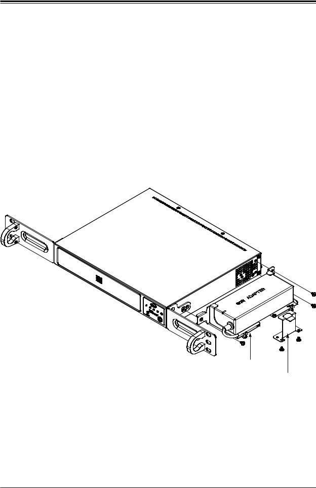
Installing Rack Mounting Brackets
The chassis can be mounted in a rack using two rack brackets and a two-part power adapter shelf bracket (optional, MCP-290-30002-0B).
1.Attach the rack brackets using three screws through the holes in each bracket to secure the bracket to the chassis.
2.Install the handles, using two screws through the bracket and into each handle.
3.If you are using the optional power adapter bracket, install the power adapter on its bracket. Place it as shown, then add the retention bracket using two screws.
4.Mount the power adapter bracket assembly on the right side of the chassis using three screws.
Rack Bracket
Rack Bracket
Power Adapter
Bracket
Power Adapter
Retention Bracket
Figure 1-5. Installing Rack Mounting Brackets
16

Chapter 2 Maintenance and Component Installation
Chapter 2
Maintenance and Component Installation
This chapter provides instructions on installing and replacing main system components. To prevent compatibility issues, only use components that match the specifications and/or part numbers given.
Installation or replacement of most components require that power first be removed from the system. Please follow the procedures given in each section.
2.1 Removing Power
Use the following procedure to ensure that power has been removed from the system. This step is necessary when removing or installing non hot-swap components or when replacing a non-redundant power supply.
1.Use the operating system to power down the system.
2.After the system has completely shut-down, disconnect the AC adapter power cord from the power source.
3.Disconnect the power cord from the chassis.
17
SuperServer E300-9D-4CN8TP/E300-9D-8CN8TP User's Manual
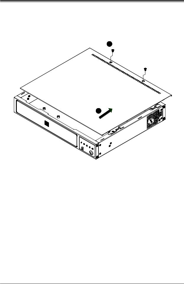
2.2 Accessing the System
The SCE300 features a removable top cover to access to the inside of the chassis.
2
3
Figure 2-1. Removing the Chassis Cover
Removing the Top Cover
1.Power down the system as described in section 2.1.
2.Remove the two screws that hold the cover in place.
3.Slide the cover sideways as illustrated above to release the front and rear cover hooks from the chassis.
4.Lift the cover up and off the chassis.
Caution: Except for short periods of time, do not operate the server without the cover in place. The chassis cover must be in place to allow proper airflow and prevent overheating.
18
Chapter 2 Maintenance and Component Installation
2.3 Motherboard Components
Processor
The E300 - 9D - 4CN8TP/E300 - 9D - 8CN8TP system features an embedded Intel® Xeon® D-2123IT, 4-core/D-2146NT, 8-core processor.
Memory Support
The X11SDV-4C-TP8F/8C-TP8F motherboard supports up to 512GB of DDR4-2666/2400/2133 ECC LRDIMM or up to 256GB of DDR4-2666/2400/2133 ECC/non-ECC RDIMM memory in four DIMM slots. Populating these DIMM slots with memory modules of the same type and size will result in interleaved memory, which will improve memory performance.
Note: Check the Supermicro website for recommended memory modules.
Memory Population (Balanced)
DIMMA1 |
DIMMB1 |
DIMMD1 |
DIMME1 |
Total System |
|
Memory |
|||||
|
|
|
|
||
|
|
|
|
|
|
4GB |
4GB |
|
|
8GB |
|
|
|
|
|
|
|
4GB |
4GB |
4GB |
4GB |
16GB |
|
|
|
|
|
|
|
8GB |
8GB |
|
|
16GB |
|
|
|
|
|
|
|
8GB |
8GB |
8GB |
8GB |
32GB |
|
|
|
|
|
|
|
16GB |
16GB |
|
|
32GB |
|
|
|
|
|
|
|
16GB |
16GB |
16GB |
16GB |
64GB |
|
|
|
|
|
|
|
32GB |
32GB |
|
|
64GB |
|
|
|
|
|
|
|
32GB |
32GB |
32GB |
32GB |
128GB |
|
|
|
|
|
|
|
64GB |
64GB |
|
|
128GB |
|
|
|
|
|
|
|
64GB |
64GB |
64GB |
64GB |
256GB |
|
|
|
|
|
|
|
128GB |
128GB |
|
|
256GB |
|
|
|
|
|
|
|
128GB |
128GB |
128GB |
128GB |
512GB |
|
|
|
|
|
|
19
SuperServer E300-9D-4CN8TP/E300-9D-8CN8TP User's Manual
Installing Memory
When installing memory modules, the DIMM slots should be populated in the following order: DIMMB1, DIMMA1, DIMME1 DIMMD1.
•Always use DDR4 DIMM modules of the same size, type and speed. Mixing memory modules of different types and speeds is not allowed.
•The motherboard will support one DIMM module installed. However, for best memory performance, install DIMM modules in pairs.
Caution: Exercise extreme care when installing or removing DIMM modules to prevent damage.
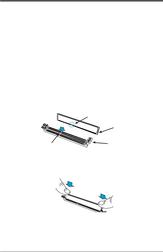
Installing Memory
Begin by removing power from the system as described in Section 2.1.
1.Starting with DIMMB1, push the release tabs outwards on both ends of the DIMM slot to unlock it.
|
Module Key |
|
Module Notch |
Socket Key |
Locking Clip |
|
2.Align the key of the DIMM with the receptive point on the memory slot and with your thumbs on both ends of the module, press it straight down into the slot until the module snaps into place.
3.Press the release tabs to the locked position to secure the DIMM module into the slot. Repeat for other DIMM slots as needed in the order given above:
To remove a DIMM, unlock the release tabs then pull the DIMM from the memory slot.
20
Chapter 2 Maintenance and Component Installation
Solid State Storage
This motherboard supports four internally mounted solid state storage cards:
•Four SATA 3.0 ports(SATA/SAS HDD/SSD).
•Two ports can be used as U.2 NVMe ports or Mini-SAS HD ports.
Figure 2-2. Installing a SATA HDD/SSD or a PCI-E NVMe SSD
21
SuperServer E300-9D-4CN8TP/E300-9D-8CN8TP User's Manual
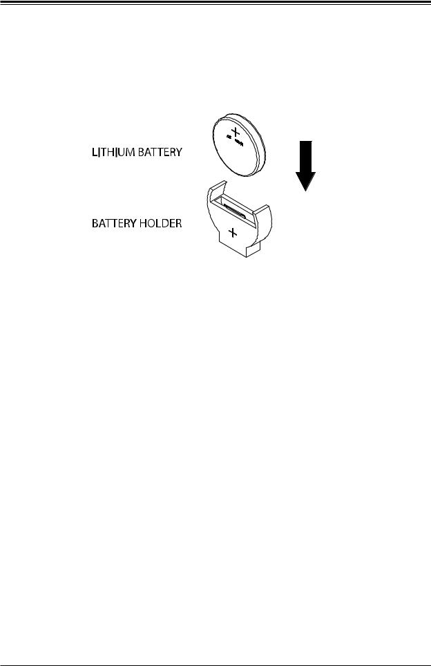
Motherboard Battery
The motherboard uses non-volatile memory to retain system information when system power is removed. This memory is powered by a lithium battery residing on the motherboard.
Figure 2-3. Installing the Onboard Battery
Replacing the Battery
1.Remove power from the system as described in section 3.1.
2.Push aside the small clamp that covers the edge of the battery. When the battery is released, lift it out of the holder.
3.To insert a new battery, slide one edge under the lip of the holder with the positive (+) side facing up. Then push the other side down until the clamp snaps over it.
Note: Handle used batteries carefully. Do not damage the battery in any way; a damaged battery may release hazardous materials into the environment. Do not discard a used battery in the garbage or a public landfill. Please comply with the regulations of your local hazardous waste management agency to dispose of your used battery properly.
Warning: There is a danger of explosion if the onboard battery is installed upside down (which reverses its polarities). This battery must be replaced only with the same or an equivalent type recommended by the manufacturer (CR2032).
22
Chapter 2 Maintenance and Component Installation
2.4 Chassis Components
Installing the Storage Drive
The SCE300 can accommodate a single fixed 2.5" storage drive. It is installed to a mounting tray inside the chassis. Use an enterprise quality drive.
Figure 2-4. Installing the Hard Drive
Installing the Hard Drive
The motherboard should be installed before installing the drive.
1.Make sure there is no power to the system as described in section 2.1 and remove the chassis cover.
2.Remove the screws securing the hard drive tray to the support bracket and set them aside for later use. Lift the tray out.
3.Place the drive into the tray and secure it to the tray with the screws provided with drive.
23

SuperServer E300-9D-4CN8TP/E300-9D-8CN8TP User's Manual
4.Return the drive tray assembly into the chassis, aligning the tabs of the tray with the slots in the chassis. Secure the tray to the chassis support bracket with the screws previously set aside.
5.Attach the cable SATA connector and to the motherboard connector. This cable carries both the SATA signal and the SATA power.
6.Reinstall the chassis cover and power up the system.
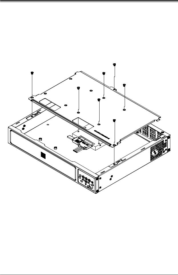
Installing the Riser Card
The system can support one PCI-E x8 expansion card by means of an optional riser card. The riser card is inserted in the expansion slot on the motherboard. Installation of the riser card and riser card bracket is pictured below.
Riser Card Bracket
Riser Card
Figure 2-5. Installing the Riser Card
24
Chapter 2 Maintenance and Component Installation
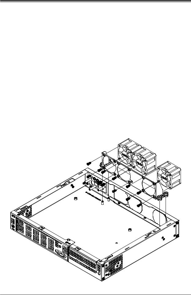
System Cooling
The SCE300 may have up to three 4-cm fans installed. The fans are optional parts.
Replacing the System Fan
1.Power down the system as described in section 2.1 and remove the AC power cord and the chassis cover.
2.Remove the failed fan power cable from motherboard.
3.Remove the screws securing the fan to the chassis wall and save them.
4.Lift the fan out of the chassis.
5.Align the replacement fan with the holes in the wall of the chassis.
6.Secure the fan to the chassis wall using the screws previously set aside.
7.Reconnect the fan cable to motherboard.
8.Reinstall the chassis top cover, reconnect the AC power cord and power up the system.
Figure 2-6. System Fans (third fan optional)
25
SuperServer E300-9D-4CN8TP/E300-9D-8CN8TP User's Manual
Chapter 3
Motherboard Connections
This section describes the connections on the X11SDV-4C-TP8F/8C-TP8F motherboard and provides pinout definitions. Note that depending on how the system is configured, not all connections are required. The LEDs on the motherboard are also described here. A motherboard layout indicating component locations may be found in Chapter 1.
Please review the safety precautions in Appendix B before installing or removing components.
3.1 Power Connections
Main ATX Power Supply Connector
The primary power supply connector (JPW1) meets the ATX SSI EPS 12V specification.
Main ATX Power Supply Connector
The primary power supply connector (JPW1) meets the ATX SSI EPS 12V specification.
ATX Power 24-pin Connector
Pin Definitions
Pin# |
|
Definition |
Pin# |
|
Definition |
13 |
|
+3.3V |
1 |
|
+3.3V |
|
|
||||
14 |
|
-12V |
2 |
|
+3.3V |
15 |
|
Ground |
3 |
|
Ground |
16 |
|
PS_ON |
4 |
|
+5V |
17 |
|
Ground |
5 |
|
Ground |
18 |
|
Ground |
6 |
|
+5V |
19 |
|
Ground |
7 |
|
Ground |
20 |
|
Res (NC) |
8 |
|
PWR_OK |
21 |
|
+5V |
9 |
|
5VSB |
22 |
|
+5V |
10 |
|
+12V |
23 |
|
+5V |
11 |
|
+12V |
24 |
|
Ground |
12 |
|
+3.3V |
|
|
|
|
|
|
26
Chapter 3 Motherboard Connections
Secondary Power Connector
JPV1 must also be connected to the power supply. This connector is used to power the process and provides alternative power for special enclosure when the 24-pin ATX power is not in use.
+12V 8-pin Power
Pin Definitions
Pin# Definition
1 - 4 Ground
5 - 8 +12V
Required Connection
HDD Power Connector
JPH1 is a 4-pin power connector for HDD use. It provides power from the motherboard to the onboard HDD.
+12V 8-pin Power
Pin Definitions
Pin# Definition
1 12V
2-3 GND
45V
3.2Headers and Connectors
Fan Headers
The X11SDV-16C/-12C/-8C-TP8F has six 4-pin fan headers (FAN1 ~ FAN4, FANA, FANB). These headers are backwards-compatible with the traditional 3-pin fans. However, fan speed control is available for 4-pin fans only by Thermal Management via the IPMI 2.0 interface.
Refer to the table below for pin definitions.
Fan Header
Pin Definitions
Pin# Definition
1Ground (Black)
22.5A/+12V (Red)
3Tachometer
4PWM_Control
27
SuperServer E300-9D-4CN8TP/E300-9D-8CN8TP User's Manual
Power LED/Buzzer Header
On the JD1 header, pins 1-4 are for the Power LED and pins 5-7 are for the buzzer.
Speaker Connector
Pin Definitions
Pin Setting |
|
Definition |
Pins 1-4 |
|
Speaker |
|
||
Pins 3-4 |
|
Buzzer |
Chassis Intrusion
A Chassis Intrusion header is located at JL1 on the motherboard. Attach the appropriate cable from the chassis to inform you of a chassis intrusion when the chassis is opened. Refer to the table below for pin definitions.
Chassis Intrusion
Pin Definitions
Pin# Definition
1Intrusion Input
2Ground
Mini PCI-E x1 Connector
This connector can support storage devices such as a mini PCI-E SSD hard drive.
General Purpose I/O Header
The JGP1 (General Purpose Input/Output) header is a general purpose I/O expander on a pin header via the SMBus. Refer to the table below for pin definitions.
SGPIO Header
Pin Definitions
Pin# |
|
Definition |
Pin# |
|
Definition |
1 |
|
+5V Power |
2 |
|
GND |
|
|
||||
3 |
|
GP0 |
4 |
|
GP1 |
5 |
|
GP2 |
6 |
|
GP3 |
7 |
|
GP5 |
8 |
|
GP5 |
9 |
|
GP6 |
10 |
|
GP7 |
|
|
|
|
|
|
Serial General Purpose I/O Header
One S-SGPIO (Serial Link General Purpose Input/Output) header is at S-SGPIO1 on the motherboard. Refer to the table below for pin definitions.
SGPIO Header
Pin Definitions
Pin# |
|
Definition |
Pin# |
|
Definition |
1 |
|
NC |
2 |
|
NC |
|
|
||||
3 |
|
GND |
4 |
|
Data |
5 |
|
Load |
6 |
|
GND |
7 |
|
Clock |
8 |
|
NC |
|
|
|
|
|
|
NC = No Connection
28
Chapter 3 Motherboard Connections
Standby Power
The +5V Standby Power header is located at JSTBY1 on the motherboard. You must have a card with a Standby Power connector and a cable to use this feature. Refer to the table below for pin definitions.
Standby Power
Pin Definitions
Pin# Definition
1+5V Standby
2Ground
3NC
Disk On Module Power Connector
One power connector for a SATA DOM (Disk On Module) device is located at JSD1. Connect the appropriate cable here to provide power support for your Serial Link DOM device.
DOM Power
Pin Definitions
Pin# Definition
15V
2Ground
3Ground
SMBus Header
A System Management Bus header for IPMI 2.0 is located at JIPMB1. Connect the appropriate cable here to use the IPMB I2C connection on your system. Refer to the table below for pin definitions.
External I2C Header
Pin Definitions
Pin# Definition
1Data
2GND
3Clock
4NC
Power SMB (I2C) Header
The Power System Management Bus (I2C) connector (JPI2C1) monitors the power supply, fan, and system temperatures. Refer to the table below for pin definitions.
Power SMB Header
Pin Definitions
Pin# Definition
1Clock
2Data
3PMBUS_Alert
4Ground
5+3.3V
29
SuperServer E300-9D-4CN8TP/E300-9D-8CN8TP User's Manual
TPM/Port 80 Header
A Trusted Platform Module (TPM)/Port 80 header is located at JTPM1 to provide TPM support and a Port 80 connection. Use this header to enhance system performance and data security.
Refer to the table below for pin definitions.
Trusted Platform Module Header
Pin Definitions
Pin# |
Definition |
Pin# |
Definition |
1 |
+3.3V |
2 |
SPI_CS# |
3 |
RESET# |
4 |
SPI_MISO |
5 |
SPI_CLK |
6 |
GND |
7 |
SPI_MOSI |
8 |
|
9 |
+3.3V Stby |
10 |
SPI_IRQ# |
System Management Bus Header
A System Management Bus header for additional slave devices or sensors is located at
JSMB1. See the table below for pin definitions.
External I2C Header
Pin Definitions
Pin# Definition
1Data
2Ground
3Clock
4NC
LAN Activity Header
JLANLED1 is the activity LED header for LAN1 through LAN4.
LAN Activity LED
Pin Definitions
Pin# Definition
13V3 Stby
2LAN3_ACT_N
33V3 Stby
4LAN4_ACT_N
SATA Ports
Twelve SATA 3.0 ports, supported by the Intel SoC chipset, are located on the X11SDV-16C/-12C/-8C-TP8F motherboard. These SATA ports support RAID 0, 1, 5, and 10. SATA ports provide serial-link signal connections. Two additional SATA connections are availabe via the M.2 connector.
30
Loading...