


 Loading...
X12SCZ-TLN4F/QF/F
USER'S MANUAL
Revision 1.0

The information in this user’s manual has been carefully reviewed and is believed to be accurate. The manufacturer assumes no responsibility for any inaccuracies that may be contained in this document, and makes no commitment to update or to keep current the information in this manual, or to notify any person or organization of the updates.
Please Note: For the most up-to-date version of this manual, please see our website at www.supermicro.com.
Super Micro Computer, Inc. ("Supermicro") reserves the right to make changes to the product described in this manual at any time and without notice. This product, including software and documentation, is the property of Supermicro and/ or its licensors, and is supplied only under a license. Any use or reproduction of this product is not allowed, except as expressly permitted by the terms of said license.
IN NO EVENT WILL Super Micro Computer, Inc. BE LIABLE FOR DIRECT, INDIRECT, SPECIAL, INCIDENTAL, SPECULATIVE OR CONSEQUENTIAL DAMAGES ARISING FROM THE USE OR INABILITY TO USE THIS PRODUCT OR DOCUMENTATION, EVEN IF ADVISED OF THE POSSIBILITY OF SUCH DAMAGES. IN PARTICULAR, SUPER MICRO COMPUTER, INC. SHALL NOT HAVE LIABILITY FOR ANY HARDWARE, SOFTWARE, OR DATA STORED OR USED WITH THE PRODUCT, INCLUDING THE COSTS OF REPAIRING, REPLACING, INTEGRATING, INSTALLING OR RECOVERING SUCH HARDWARE, SOFTWARE, OR DATA.
Any disputes arising between manufacturer and customer shall be governed by the laws of Santa Clara County in the State of California, USA. The State of California, County of Santa Clara shall be the exclusive venue for the resolution of any such disputes. Supermicro's total liability for all claims will not exceed the price paid for the hardware product.
FCC Statement: This equipment has been tested and found to comply with the limits for a Class A digital device pursuant to Part 15 of the FCC Rules. These limits are designed to provide reasonable protection against harmful interference when the equipment is operated in a commercial environment. This equipment generates, uses, and can radiate radio frequency energy and, if not installed and used in accordance with the manufacturer’s instruction manual, may cause harmful interference with radio communications. Operation of this equipment in a residential area is likely to cause harmful interference, in which case you will be required to correct the interference at your own expense.
California Best Management Practices Regulations for Perchlorate Materials: This Perchlorate warning applies only to products containing CR (Manganese Dioxide) Lithium coin cells. “Perchlorate Material-special handling may apply. See www.dtsc.ca.gov/hazardouswaste/perchlorate”.
WARNING: This product can expose you to chemicals including
!lead, known to the State of California to cause cancer and birth defects or other reproductive harm. For more information, go to www.P65Warnings.ca.gov.
The products sold by Supermicro are not intended for and will not be used in life support systems, medical equipment, nuclear facilities or systems, aircraft, aircraft devices, aircraft/emergency communication devices or other critical systems whose failure to perform be reasonably expected to result in significant injury or loss of life or catastrophic property damage. Accordingly, Supermicro disclaims any and all liability, and should buyer use or sell such products for use in such ultra-hazardous applications, it does so entirely at its own risk. Furthermore, buyer agrees to fully indemnify, defend and hold Supermicro harmless for and against any and all claims, demands, actions, litigation, and proceedings of any kind arising out of or related to such ultra-hazardous use or sale.
Manual Revision 1.0
Release Date: July 30, 2020
Unless you request and receive written permission from Super Micro Computer, Inc., you may not copy any part of this document. Information in this document is subject to change without notice. Other products and companies referred to herein are trademarks or registered trademarks of their respective companies or mark holders.
Copyright © 2020 by Super Micro Computer, Inc.
All rights reserved.
Printed in the United States of America
Preface
Preface
About This Manual
This manual is written for system integrators, IT technicians and knowledgeable end users. It provides information for the installation and use of the X12SCZ-TLN4F/QF/F motherboard.
About This Motherboard
The X12SCZ series comes in different model variations with different CPU support. The
X12SCZ-TLN4F/F supports Intel® Xeon W-1200 series, 10th Generation Core i9/i7/i5/i3, Pentium, and Celeron processors in an LGA1200 socket, while the X12SCZ-QF supports Intel 10th Generation Core i9/i7/i5/i3, Pentium, and Celeron processors in an LGA1200 socket. The X12SCZ-TLN4F/F features the W480E chipset and support for ECC and NonECC DDR4 UDIMM memory, while the X12SCZ-QF features the Q470E chipset and support for Non-ECC only. The X12SCZ series motherboards include the PCI Express 3.0 interface, four SATA 3.0 ports, IPMI 2.0, 12V DC power source, GPU add-on card power connector, dual 10GbE LAN option (on -TLN4F), HD Graphic outputs, and a combination of USB 2.0 and 3.2 ports. The motherboards also provide security-enhancing technologies such as Intel Software Guard Extensions (Intel SGX), Intel vPro, and Intel Trusted Execution Technology
(TXT). The X12SCZ-TLN4F/QF/F offers exceptional system performance for entry server, data storage, network security, and embedded applications.
Conventions Used in the Manual
Special attention should be given to the following symbols for proper installation and to prevent damage done to the components or injury to yourself:
Warning! Indicates important information given to prevent equipment/property damage or personal injury.
 Warning! Indicates high voltage may be encountered while performing a procedure.
Important: Important information given to ensure proper system installation or to relay safety precautions.
Note: Additional Information given to differentiate various models or provides information for proper system setup.
3

Super X12SCZ-TLN4F/QF/F User's Manual
Contacting Supermicro
Headquarters |
|
Address: |
Super Micro Computer, Inc. |
|
980 Rock Ave. |
|
San Jose, CA 95131 U.S.A. |
Tel: |
+1 (408) 503-8000 |
Fax: |
+1 (408) 503-8008 |
Email: |
marketing@supermicro.com (General Information) |
|
support@supermicro.com (Technical Support) |
Website: |
www.supermicro.com |
Europe |
|
Address: |
Super Micro Computer B.V. |
|
Het Sterrenbeeld 28, 5215 ML |
|
's-Hertogenbosch, The Netherlands |
Tel: |
+31 (0) 73-6400390 |
Fax: |
+31 (0) 73-6416525 |
Email: |
sales@supermicro.nl (General Information) |
|
support@supermicro.nl (Technical Support) |
|
rma@supermicro.nl (Customer Support) |
Website: |
www.supermicro.nl |
Asia-Pacific |
|
Address: |
Super Micro Computer, Inc. |
|
3F, No. 150, Jian 1st Rd. |
|
Zhonghe Dist., New Taipei City 235 |
|
Taiwan (R.O.C) |
Tel: |
+886-(2) 8226-3990 |
Fax: |
+886-(2) 8226-3992 |
Email: |
support@supermicro.com.tw |
Website: |
www.supermicro.com.tw |
4

Preface
|
Table of Contents |
|
Chapter 1 Introduction |
|
|
1.1 |
Checklist................................................................................................................................ |
8 |
|
Quick Reference................................................................................................................ |
11 |
|
Quick Reference Table...................................................................................................... |
12 |
|
Motherboard Features....................................................................................................... |
14 |
1.2 |
Processor and Chipset Overview....................................................................................... |
18 |
1.3 |
Special Features................................................................................................................. |
19 |
|
Recovery from AC Power Loss......................................................................................... |
19 |
1.4 |
System Health Monitoring................................................................................................... |
19 |
|
Onboard Voltage Monitors................................................................................................. |
19 |
|
Fan Status Monitor with Firmware Control........................................................................ |
19 |
|
Environmental Temperature Control.................................................................................. |
19 |
|
System Resource Alert...................................................................................................... |
20 |
1.5 |
ACPI Features.................................................................................................................... |
20 |
1.6 Power Supply....................................................................................................................... |
20 |
|
1.7 |
Serial Port........................................................................................................................... |
21 |
Chapter 2 Installation |
|
|
2.1 |
Static-Sensitive Devices..................................................................................................... |
22 |
|
Precautions........................................................................................................................ |
22 |
|
Unpacking.......................................................................................................................... |
22 |
2.2 |
Processor and Heatsink Installation................................................................................... |
23 |
|
Installing the LGA1200 Processor..................................................................................... |
23 |
|
Installing an Active CPU Heatsink with Fan...................................................................... |
25 |
|
Removing the Heatsink...................................................................................................... |
27 |
2.3 |
Motherboard Installation..................................................................................................... |
28 |
|
Tools Needed..................................................................................................................... |
28 |
|
Location of Mounting Holes............................................................................................... |
28 |
|
Installing the Motherboard................................................................................................. |
29 |
2.4 |
Memory Support and Installation........................................................................................ |
30 |
|
Memory Support................................................................................................................ |
30 |
|
DIMM Module Population Configuration............................................................................ |
30 |
5

Super X12SCZ-TLN4F/QF/F User's Manual
|
General Guidelines for Optimizing Memory Performance................................................. |
31 |
|
DIMM Installation............................................................................................................... |
32 |
|
DIMM Removal.................................................................................................................. |
32 |
2.5 |
Rear I/O Ports..................................................................................................................... |
33 |
2.6 |
Front Control Panel............................................................................................................. |
39 |
2.7 |
Connectors.......................................................................................................................... |
44 |
|
Power Connections............................................................................................................ |
44 |
|
Headers............................................................................................................................. |
47 |
2.8 |
Jumper Settings.................................................................................................................. |
57 |
|
How Jumpers Work........................................................................................................... |
57 |
2.9 |
LED Indicators.................................................................................................................... |
64 |
Chapter 3 Troubleshooting |
|
|
3.1 |
Troubleshooting Procedures............................................................................................... |
66 |
|
Before Power On............................................................................................................... |
66 |
|
No Power........................................................................................................................... |
66 |
|
No Video............................................................................................................................ |
67 |
|
System Boot Failure ........................................................................................................ |
67 |
|
Memory Errors................................................................................................................... |
67 |
|
Losing the System's Setup Configuration.......................................................................... |
68 |
|
When the System Becomes Unstable............................................................................... |
68 |
3.2 |
Technical Support Procedures............................................................................................ |
70 |
3.3 |
Frequently Asked Questions............................................................................................... |
71 |
3.4 |
Battery Removal and Installation........................................................................................ |
72 |
|
Battery Removal................................................................................................................ |
72 |
|
Proper Battery Disposal..................................................................................................... |
72 |
|
Battery Installation............................................................................................................. |
72 |
3.5 |
Returning Merchandise for Service.................................................................................... |
73 |
Chapter 4 UEFI BIOS |
|
|
4.1 |
Introduction......................................................................................................................... |
74 |
4.2 |
Main Setup.......................................................................................................................... |
75 |
4.3 |
Advanced Setup Configurations......................................................................................... |
77 |
4.4 |
Event Logs........................................................................................................................ |
111 |
4.5 |
IPMI................................................................................................................................... |
113 |
6

Preface
4.6 |
Security............................................................................................................................. |
116 |
4.7 |
Boot................................................................................................................................... |
123 |
4.8 |
Save & Exit....................................................................................................................... |
126 |
Appendix A BIOS Codes |
|
|
A.1 |
BIOS Error POST (Beep) Codes...................................................................................... |
128 |
A.2 |
Additional BIOS POST Codes.......................................................................................... |
129 |
Appendix B Software |
|
|
B.1 |
Microsoft Windows OS Installation................................................................................... |
130 |
B.2 |
Driver Installation.............................................................................................................. |
132 |
B.3 |
SuperDoctor® 5................................................................................................................. |
133 |
B.4 |
IPMI................................................................................................................................... |
134 |
Appendix C Standardized Warning Statements |
|
|
Appendix D UEFI BIOS Recovery |
|
|
D.1 |
Overview........................................................................................................................... |
138 |
D.2 |
Recovering the UEFI BIOS Image.................................................................................... |
138 |
D.3 |
Recovering the BIOS Block with a USB Device............................................................... |
138 |
7
Super X12SCZ-TLN4F/QF/F User's Manual
Chapter 1
Introduction
Congratulations on purchasing your computer motherboard from an industry leader. Supermicro motherboards are designed to provide you with the highest standards in quality and performance.
In additon to the motherboard, several important parts that are included in the retail box are listed below. If anything listed is damaged or missing, please contact your retailer.
1.1 Checklist
Main Parts List
Description |
Part Number |
Quantity |
Supermicro Motherboard |
X12SCZ-TLN4F/QF/F |
1 |
I/O Shield |
MCP-260-00093-0N |
1 |
SATA Cables |
CBL-0044L |
4 |
Quick Reference Guide |
MNL-2257-QRG |
1 |
|
|
|
Important Links
For your system to work properly, please follow the links below to download all necessary drivers/utilities and the user’s manual for your server.
•Supermicro product manuals: http://www.supermicro.com/support/manuals/
•Product drivers and utilities: https://www.supermicro.com/wftp/driver
•Product safety info: http://www.supermicro.com/about/policies/safety_information.cfm
•A secure data deletion tool designed to fully erase all data from storage devices can be found at our website: https://www.supermicro.com/about/policies/disclaimer.cfm?url=/wftp/ utility/Lot9_Secure_Data_Deletion_Utility/
•If you have any questions, please contact our support team at: support@supermicro.com
This manual may be periodically updated without notice. Please check the Supermicro website for possible updates to the manual revision level.
8

Chapter 1: Introduction
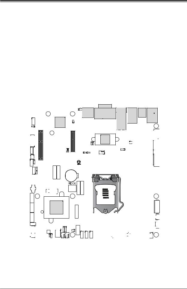
Figure 1-1. X12SCZ-TLN4F Motherboard Image
Note 1: LAN ports 3/4 are only available on X12SCZ-TLN4F.
 Note 2: All graphics shown in this manual were based upon the latest PCB revision available at the time of publication of the manual. The motherboard you received may or may not look exactly the same as the graphics shown in this manual.
9
Super X12SCZ-TLN4F/QF/F User's Manual
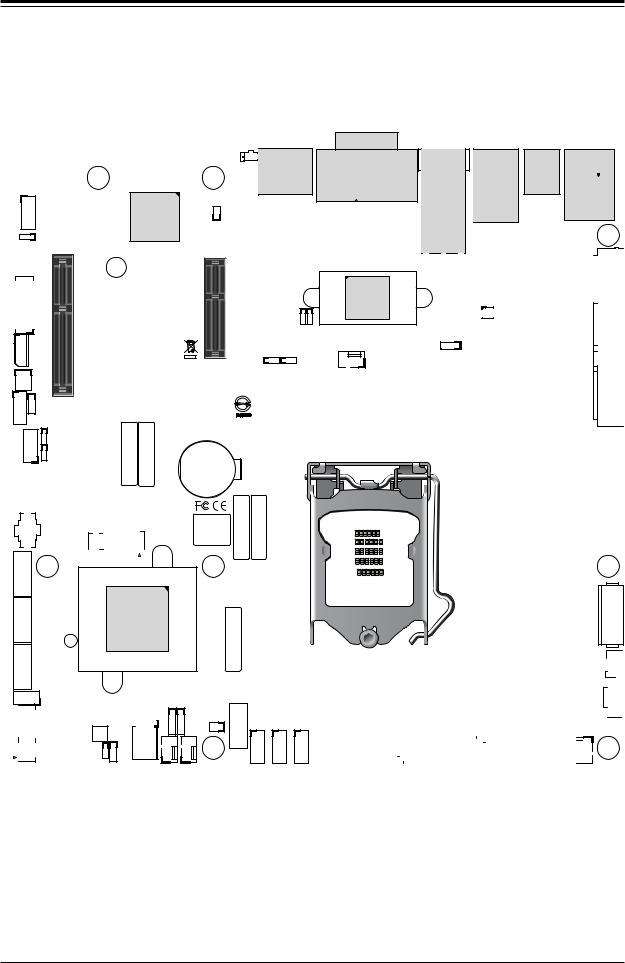
Figure 1-2. X12SCZ-QF Motherboard Layout
(not drawn to scale)
AUDIO FP |
MH8 |
LED1UID |
SWUID |
|
|
MH4 |
|
|
|
|
DP++1/2 |
|
|
JBM1 |
|
JPAC1 |
|
|
|
COM1/2 |
PCH |
|
X8) (IN X4 0.3 PCIe SLOT4 |
||
JIPMB1 |
||
J18 |
|
|
JPME2 |
||
JGP1 |
|
|
JTPM1 |
JPG1 |
|
JPT1 |
||
USB10/11 (3.2 10Gb)
MH1
SLT4JPCIE |
SRW4 |
LED1HB BMC |
|
|
SRW2
CODE BAR
CODE SAN
ART1
JMD2
JPCIE6
X16 0.3 PCIe SLOT6 CPU
CODE BAR
SLOT7 PCH |
SLT7 JPCIE |
X4 0.3 PCIe |
|
JPL1 JPL2
JPTG1 PWR_J10G
JPL3/4:LAN3/4 1-2:ENABLE 2-3:DISABLE
BT1
+
|
BAR |
BAR |
BIOS LICENSE |
CODE |
CODE |
-I |
|
SATA3 |
MH5 |
|
-I |
|
|
Intel |
|
BAR |
SATA2 |
|
JBT1 |
W480/Q470 |
||
|
|
|
|
||
SATA1-I |
SP1 |
|
|
|
CODE |
|
|
|
|
|
|
|
I-SGPIO1 |
|
JSMB1 JD1 |
I-SATA0 |
|
|
|
|
|||
|
|
|
JPWR1 |
FANB |
JL1 |
JMD1 |
|
FANA |
|||
|
|
SRW3 |
|
|
JSD1 |
|
|
JWD1 |
|
|
|
|
|
JRF1 |
|
MH7 |
|
|
|
|
|
||
USB0/1 |
USB2/3 |
USB4/5 |
DVI-D/VGA
JLAN1/2
JLAN3/4
JBM2
JVRM1
FAN4
USB6/7 (3.2 10G)
IPMI_LAN USB8/9(3.2 10G) 


MH3 


 JPW1 JPV1
X12SCZ-QF
REV:1.01
DESIGNED IN USA
|
|
|
|
|
|
|
|
|
|
|
|
|
|
|
|
|
|
|
|
|
|
|
|
|
|
|
|
|
|
|
|
JF1: |
|
|
|
|
|
|
|
|
|
|
|
|
|
|
ON |
RST |
X |
FF |
NIC2 |
NIC1 |
LED |
LED |
NMI |
|
|
|
|
|
|
PWR |
|
|
OH |
|
|
HDD |
PWR |
|
|
|
|
|
|
|
|
|
|
|
|
|
|
|
|
LED1 |
|
FAN3 |
|
|
|
|
|
|
|
|
|
JF1 |
|
|
|
|||
|
|
|
|
|
|
|
|
|
|
|
|
|
|
|
DIMMB2
DIMMB1
DIMMA2
DIMMA1
MH2
JPH1
 JPI2C1 FAN1
 MH6 FAN2


Note 1: LAN ports 3/4 are only available on X12SCZ-TLN4F.
 Note 2: Components not documented are for internal testing only.
10
Chapter 1: Introduction
|
|
|
|
|
|
|
|
|
|
|
|
Quick Reference |
|
|
|
|
|
|
||||||
|
AUDIO FP |
SRW4 |
|
|
|
|
JBM1 UID_LED1 |
|
|
|
|
|
JLAN1/2 |
|
IPMI_LAN |
|||||||||
|
|
|
|
|
SLOT7 |
|
UID SW |
DVI-D/VGA |
|
|
|
|
||||||||||||
|
|
|
|
|
|
|
|
|
|
|
|
|
USB6/7 |
USB8/9 |
|
|||||||||
|
|
|
|
|
|
|
|
|
|
|
|
|
DP++1/2 |
|
|
JLAN3/4 |
|
|||||||
|
|
|
|
|
SLOT6 |
|
|
|
|
|
|
|
|
|||||||||||
|
|
|
|
|
|
|
|
|
|
|
|
|
|
|
||||||||||
|
|
|
|
|
|
|
|
|
|
|
|
|
|
|
|
|
|
|
|
|
||||
|
AUDIO FP |
MH8 |
|
|
|
|
MH4 |
LED1UID |
SWUID |
|
|
|
|
|
|
|
|
|
|
|
||||
|
|
|
|
|
|
|
|
|
|
|
|
|
|
|
|
|
|
|
|
|
|
|
||
|
|
|
|
|
|
|
|
|
|
|
|
|
DP++1/2 |
|
DVI-D/VGA |
|
|
|
|
USB6/7 |
|
|
||
|
|
|
|
|
|
|
|
|
|
JBM1 |
|
|
|
|
|
|
|
|
(3.2 10G) |
|
|
|||
|
|
|
|
|
|
|
|
|
|
|
|
|
|
|
|
|
|
|
|
|
|
|
||
|
|
|
|
|
|
|
|
|
|
|
|
|
|
|
|
|
|
|
|
JLAN1/2 |
|
IPMI_LAN |
|
|
JPAC1 |
|
JPAC1 |
|
|
|
|
|
|
|
|
|
|
|
|
|
|
|
|
|
USB8/9(3.2 10G) |
|
|||
|
|
|
|
|
|
|
|
|
|
|
|
|
|
|
|
|
|
|
|
|||||
|
|
|
|
|
|
|
|
|
|
|
|
|
|
|
|
|
|
|
|
MH3 |
|
|||
|
|
|
|
|
|
|
|
|
|
|
|
|
|
|
|
|
|
|
|
|
|
|
||
|
|
|
|
|
SLT4 JPCIE X8)(INX40.3 PCIe SLOT4 PCH |
|
LED1 HB BMC |
JPCIE6 |
|
|
SLT7 JPCIE X40.3 PCIe SLOT7 PCH |
|
|
|
|
|
|
JLAN3/4 |
|
|
|
|
|
|
|
|
JIPMB1 |
|
|
|
X160.3PCIeSLOT6CPU |
|
|
|
|
|
PWR |
|
|
|
|
|
|
JPW1 |
JVRM1 |
||||
|
|
|
|
|
|
|
|
2-3:DISABLE |
|
|
|
|
|
|
|
|
||||||||
|
COM1/2 |
|
|
|
|
|
|
|
|
|
|
|
|
|
|
|
|
|
|
|
|
JPV1 |
JPV1 |
|
COM1/2 |
|
|
|
|
SRW4 |
|
|
|
|
|
|
|
|
|
|
|
|
|
|
|
|
|
J10G_PWR |
|
|
|
|
|
|
|
|
|
|
|
|
|
|
|
|
|
|
|
|
JBM2 |
|
|
|
||
SLOT4 |
|
|
|
|
|
|
|
|
|
|
|
|
|
|
J10G |
|
|
|
|
|
|
|
|
JBM2 |
|
|
|
|
|
|
|
|
|
|
|
|
|
|
|
|
|
|
|
|
|
|
JPTG1 |
||
|
|
|
|
|
|
|
|
|
|
|
|
|
|
|
|
|
|
JVRM1 |
|
|
|
|
||
|
|
|
|
|
|
|
|
|
|
|
|
|
|
|
JPTG1 |
FAN4 |
|
|
|
|
|
|
|
JPW1 |
JIPMB1 |
|
|
|
|
|
|
|
|
|
|
|
|
JPL1 JPL2 |
|
|
|
|
|
|
|
|
|||
|
|
|
|
|
|
|
|
|
|
|
|
|
|
|
|
|
|
|
|
|
||||
|
|
|
|
|
|
|
|
|
|
|
|
|
|
|
|
|
|
|
|
|
|
|
||
J18 |
|
J18 |
|
SRW2 |
|
|
|
|
|
|
JPL3/4:LAN3/4 |
|
|
|
|
|
|
|
|
|
|
|
||
|
|
|
|
|
|
|
|
|
|
|
|
|
|
|
|
|
|
|
|
|
||||
|
|
|
|
|
|
|
|
|
|
|
|
|
1-2:ENABLE |
|
|
|
|
|
|
|
|
|
|
|
JGP1 |
|
JPME2 |
|
|
|
|
|
|
|
|
|
|
|
|
X12SCZ-QF |
|
|
|
|
|
FAN4 |
|||
JPME2 |
|
|
|
|
|
|
|
|
|
|
|
|
|
|
|
|
|
|
||||||
|
JGP1 |
|
|
|
|
|
|
|
|
|
|
|
|
|
|
|
|
|
|
|||||
JPG1 |
|
|
JPG1 |
CODESAN |
CODEBAR |
CODEBAR |
|
|
|
|
|
|
|
REV:1.01 |
|
|
|
|
|
|
|
JPL2 |
||
JTPM1 |
|
|
|
|
|
|
|
|
DESIGNED IN USA |
|
|
|
|
|
|
|||||||||
|
|
|
|
|
|
|
|
|
|
|
|
|
|
|
|
|
|
|||||||
JTPM1 |
|
JPT1 |
|
|
|
|
|
|
|
|
|
|
|
|
|
|
|
JPL1 |
||||||
|
|
|
|
|
|
|
|
|
|
|
|
|
|
|
|
|
|
|
|
|
||||
|
|
|
|
|
|
|
|
|
|
|
|
|
|
|
|
|
|
|
|
|
|
|
||
JPT1 |
|
|
|
|
|
|
|
|
|
|
|
BT1 |
|
|
|
|
|
|
|
|
|
|
BT1 |
|
|
|
|
|
ART1 |
|
|
|
|
|
|
+ |
BAR |
|
|
|
|
|
|
|
|
|
DIMMB2 DIMMB1 DIMMA2 DIMMA1 |
||
ART1 |
|
|
|
|
|
|
|
|
|
|
BAR |
|
|
|
|
|
|
|
|
|
DIMMA1 |
|||
|
|
|
|
|
|
|
|
|
|
|
|
|
|
|
|
|
|
|
|
|
|
|||
USB10/11 (3.2 10Gb) |
|
|
|
|
|
|
|
|
|
|
|
|
|
|
|
|
|
|
||||||
USB10/11 |
|
|
|
|
|
|
|
|
|
|
|
|
|
|
|
|
|
|
||||||
|
|
|
|
JMD2 |
|
|
|
|
BIOS LICENSE |
CODE |
CODE |
|
|
|
|
|
|
|
|
|
|
DIMMA2 |
||
JMD2 |
|
|
|
|
|
|
|
|
|
|
|
|
|
|
|
|
|
|
||||||
|
MH1 |
|
|
|
|
|
|
|
|
|
|
|
|
|
|
|
|
|
MH2 |
DIMMB1 |
||||
|
|
|
|
|
|
|
|
|
|
|
|
|
|
|
|
|
|
|
|
|||||
|
|
|
|
|
|
|
|
|
|
|
|
|
|
|
|
|
|
|
|
|
||||
I-SATA3 |
|
-I |
|
|
|
|
|
|
|
|
|
|
|
|
|
|
|
|
|
|
|
|
|
DIMMB2 |
|
SATA3 |
|
|
|
|
|
|
|
|
MH5 |
|
|
|
|
|
|
|
|
|
|
|
|
|
|
I-SATA2 |
|
|
|
|
|
|
|
|
|
|
|
|
|
|
|
|
|
|
|
|
|
|
JPH1 |
|
|
SATA2-I |
|
|
|
|
Intel |
|
|
|
BAR |
|
|
|
|
|
|
|
|
|
|
JPH1 |
|||
JBT1 |
|
|
JBT1 |
W480/Q470 |
|
|
|
|
|
|
|
|
|
|
|
|
|
|||||||
|
|
|
|
|
|
|
|
|
|
|
|
|
|
|
|
|
|
|
|
|||||
I-SATA1 |
|
SATA1-I |
SP1 |
|
|
|
|
|
|
|
|
CODE |
|
|
|
|
|
|
|
|
|
|
FAN1 |
|
SP1 |
|
|
|
|
|
|
|
|
|
|
|
|
|
|
|
|
|
|
|
|
FAN1 |
|||
JSMB1 |
|
|
|
|
|
|
|
|
JSMB1 JD1 |
|
|
|
|
|
|
|
|
|
|
|
|
JPI2C1 |
JPI1C1 |
|
I-SGPIO1 |
|
|
I-SGPIO1 |
|
|
JPWR1 |
I-SATA0 |
|
|
JF1: |
|
|
|
|
|
|
||||||||
JD1 |
|
|
|
|
|
|
|
|
JL1 |
|
|
|
|
ON |
FF |
LED LED |
|
|
|
|
|
|
||
|
|
JMD1 |
|
|
JWD1 |
|
|
FANB |
FANA |
|
USB0/1 |
USB2/3 |
USB4/5 |
PWR RST X |
OH NIC2 NIC1 |
HDD PWR |
X NMI |
|
|
|
|
|
||
|
|
|
|
|
|
|
|
|
|
|
LED1 |
|
|
|
|
|
||||||||
JMD1 |
|
|
|
SRW3 |
|
|
|
|
JSD1 |
|
|
|
|
|
|
|
|
FAN3 |
|
|
MH6 |
|
||
|
|
|
|
|
|
|
|
|
|
|
|
|
|
|
JF1 |
|
|
|
||||||
|
|
|
|
JRF1 |
|
|
|
|
|
MH7 |
|
|
|
|
|
|
|
FAN2 |
|
|||||
|
|
|
|
|
|
|
|
|
|
|
|
|
|
|
|
|
|
|
|
|||||
|
|
|
|
JRF1 |
|
|
|
|
|
|
|
|
USB4/5 |
|
JF1 |
|
FAN3 |
|
|
FAN2 |
|
|||
|
|
SRW3 |
JWD1 |
|
|
|
|
|
USB2/3 |
|
|
|
|
|
|
|
|
|
||||||
|
|
|
|
|
|
|
USB0/1 |
|
|
|
|
LED1 |
|
|
|
|
||||||||
|
|
|
|
|
JPWR1 |
|
|
|
|
|
|
|
|
|
|
|
||||||||
|
|
|
|
|
|
|
|
FANB |
|
|
I-SATA0 |
|
|
|
|
|
|
|
|
|
|
|
||
|
|
|
|
|
|
|
|
|
FANA |
JSD1 |
|
|
|
|
|
|
|
|
|
|
|
|
||
|
|
|
|
|
|
|
|
|
|
JL1 |
|
|
|
|
|
|
|
|
|
|
|
|
|
|
Notes:
 • See Chapter 2 for detailed information on jumpers, I/O ports, and JF1 front panel connections.
•
•
•
" " indicates the location of Pin 1.
Jumpers/LED indicators not indicated are used for testing only.
Use only the correct type of onboard CMOS battery as specified by the manufacturer. Do not install the onboard battery upside down to avoid possible explosion.
11

Super X12SCZ-TLN4F/QF/F User's Manual
Quick Reference Table
Jumper |
Description |
Default Setting (*) |
|
J10G_PWR |
LAN3/LAN4 Power Option |
*Pins 1-2: Standby Power |
|
Pins 2-3: Normal Power |
|||
|
|
||
JBM1 |
IPMI Share LAN Feature |
Pins 1-2 Open (Enabled) |
|
JBM2 |
IPMI LAN Enable/Disable |
*Pins 1-3 Short (Enabled) |
|
Pins 1-2 Short (Disabled) |
|||
|
|
||
JBT1 |
CMOS Clear |
Open (Normal) |
|
JPAC1 |
Front Panel Audio EnableDisable |
Pins 1-2 (Enabled) |
|
JPG1 |
VGA Enable/Disable |
Pins 1-2 (Enabled) |
|
JPL1 |
LAN1 Enable/Disable |
Pins 1-2 (Enabled) |
|
JPL2 |
LAN2 Enable/Disable |
Pins 1-2 (Enabled) |
|
JPME2 |
Manufacturing Mode Select |
Pins 1-2 (Normal) |
|
JRF1 |
Slot6 PCIe Bifurcation Option |
*Pins 1-2 (x16) |
|
Pins 2-3 (x8x8) |
|||
|
|
||
JPT1 |
Onboard TPM Module Enable/Disable |
Pins 2-3 (Disabled) |
|
JPTG1 |
LAN3/LAN4 Enable/Disable |
Pins 1-2 (Enabled) |
|
JWD1 |
Watch Dog Timer |
Pins 1-2 (Reset) |
LED |
Description |
Status |
|
BMC_HB_LED1 |
BMC Heartbeat LED |
Blinking Green: BMC Normal |
|
UID_LED1 |
Unit Identifier (UID) LED |
Solid Blue: Unit Identified |
|
LED1 |
Power LED |
Solid Green: Power On |
|
Blinking Green: S3 Status |
|||
|
|
Connector |
Description |
ART1 |
M.2 M-Key Temperature Sensor |
AUDIO_FP |
Front Panel Audio Header |
BT1 |
Onboard Battery |
COM1/2 |
COM Header (supports RS-232) |
DP++ 1/2 |
DisplayPorts 1 and 2 |
DVI-D/VGA |
DVI-D/VGA port |
FAN1 - FAN4, FANA, FANB |
CPU/System Fan Headers (FAN1: CPU Fan) |
IPMI_LAN |
Dedicated IPMI LAN Port |
I-SATA0 - I-SATA3 |
Intel® PCH SATA 3.0 Ports (I-SATA0: SATA DOM) |
I-SGPIO1 |
Serial Link General Purpose I/O Header |
J18 |
Extended CMOS Battery Connector |
JD1 |
Speaker Header (Pins 1-4: Speaker, Pins 3-4: Buzzer) |
JF1 |
Front Control Panel Header |
JGP1 |
General Purpose I/O Header |
 Note: Table is continued on the next page.
12

Chapter 1: Introduction
Connector |
Description |
|
JIPMB1 |
4-pin BMC External I2C Header (for an IPMI card) |
|
JL1 |
Chassis Intrusion Header |
|
JLAN1/2 |
1G Base-T LAN Ports |
|
JLAN3/4 |
10G Base-T LAN Ports |
|
JMD1 |
M.2 E-Key 2230 (CNVi/CNV) Slot |
|
JMD2 |
M.2 M-Key 2280/22110 Slot |
|
JPCIE_SLT4 |
PCH PCIe 3.0 x4 (in x8) Slot |
|
JPCIE6 |
CPU PCIe 3.0 x16 Slot |
|
JPCIE_SLT7 |
PCH PCIe 3.0 x4 Slot |
|
JPH1 |
4-pin HDD Power Connector |
|
JPI2C1 |
Power System Management Bus (SMB) I2C Header |
|
JPV1 |
8-pin 12V DC Power Connector for CPU (Required) or alternative single power for special |
|
enclosure when the 24-pin ATX power is not in use |
||
|
||
JPW1 |
24-pin ATX Power Connector |
|
JPWR1 |
4-pin 12V Power Connector for GPU card requiring extra 12V power (up to 75W) |
|
JSD1 |
SATA DOM Power Connector |
|
JSMB1 |
System Management Bus Header |
|
JTPM1 |
Trusted Platform Module/Port 80 Connector |
|
SP1 |
Internal Buzzer |
|
SRW2 |
M.2 Holding Screws for M-Key Type 2280 |
|
SRW3 |
M.2 Holding Screws for E-Key Type 2230 |
|
SRW4 |
M.2 Holding Screws for M-Key Type 22110 |
|
UID SW |
Unit Identifier Switch |
|
USB0/1, 2/3, 3/4 |
USB 2.0 Headers |
|
USB6/7, 8/9 |
Back Panel USB 3.2 (10Gb) Ports |
|
USB10/11 |
USB 3.2 (10Gb) Type-A Header |
13
Super X12SCZ-TLN4F/QF/F User's Manual
Motherboard Features
Motherboard Features
CPU
•X12SCZ-TLN4F/F: Intel 10th Generation Core i9/i7/i5/i3, Pentium, Celeron, and Xeon W-1200 series processors in an LGA1200 socket.
•X12SCZ-QF: Intel 10th Generation Core i9/i7/i5/i3, Pentium, and Celeron processor in an LGA1200 socket.
Memory
•X12SCZ-TLN4F/F: Integrated memory controller supports up to 128GB Unbuffered ECC/Non-ECC UDIMM, DDR4-
2933MHz, in four DIMM slots.
•X12SCZ-QF: Integrated memory controller supports up to 128GB Unbuffered Non-ECC UDIMM, DDR4-2933MHz, in four
DIMM slots.
DIMM Size
•4GB, 8GB, 16GB, 32GB at 1.2V
Note: For the latest CPU/memory updates, please refer to our website at http://www.supermicro.com/products/ motherboard.
Chipset
•X12SCZ-F/TLN4F: Intel PCH W480E
•X12SCZ-QF: Intel PCH Q470E
Expansion Slots
•One PCIe 3.0 x4 Slot (IN x8) (PCH SLOT4)
•One PCIe 3.0 x16 Slot (CPU SLOT6) (Supports PCI-E x8x8 bifurcation by riser card)
•One PCIe 3.0 x4 Slot (PCH SLOT7)
Network
•Intel I219LM Gigabit Ethernet PHY (LAN1): Intel AMT Management Port
•Intel I210-AT Gigabit Ethernet Controller (LAN2): IPMI Shared LAN Port
•Intel X550 Dual 10GbE Ethernet Controller (LAN3/4, TLN4F SKU Only)
Baseboard Management Controller (BMC)
•ASpeed AST 2500 Baseboard Controller (BMC) supports IPMI 2.0
•One Dedicated IPMI LAN located on the rear IO back panel
Graphics
•Intel HD Graphics (DVI-D, DisplayPort1/DisplayPort2 Version 1.4) with three independent displays
•Graphics controller via ASpeed 2500 BMC (VGA)
I/O Devices
• |
Serial (COM) Header |
• One front accessible header for dual serial ports (COM1/2) |
|
• |
I-SATA 3.0 |
• Four SATA 3.0 ports with lock (I-SATA0 - I-SATA3) |
|
• |
Video (VGA) Port |
• One VGA connection on the rear I/O panel |
|
• |
DVI-D |
• One Digital Visual Interface (Digital signal only) |
|
• |
DisplayPort |
• |
Two DisplayPorts |
• |
Audio |
• |
One Audio Front Panel |
 Note: The table above is continued on the next page.
14
Chapter 1: Introduction
Motherboard Features
USB
•Four Back Panel USB 3.2 (10Gb) ports (USB6/7, USB8/9)
•Three Front Accessible USB 2.0 headers (USB0/1, USB2/3, USB4/5)
•One USB 3.2 (10Gb) header (USB10/11)
BIOS
•256Mb AMI BIOS® SPI Flash BIOS
•ACPI 6.0, Plug and Play (PnP), riser card auto detection support, SPI dual/quad speed support, and RTC (Real Time Clock wakeup
Power Management
•ACPI power management
•S3, S4, S5
•Power button override mechanism
•Power-on mode for AC power recovery
•Wake-on-LAN (JWOL)
•Power supply monitoring
System Health Monitoring
•Onboard voltage monitoring for +12V, +5V, +3.3V, +5V stdby, +3.3V stdby, Vcore, CPU temperature, PCH temperature, system temperature, M.2 NvMe (M-Key) temperature and memory temperature
•3 CPU power, 1 PCH power, 1 BMC power
•CPU thermal trip support
•Platform Environment Control Interface (PECI)/TSI
Fan Control
•Fan status monitoring via IPMI connections
•Low-noise fan speed control
•Six 4-pin fan headers
System Management
•IPMI Vieew, SMCIPMITOOL, IPMICFG
•Trusted Platform Module (TPM) support
•SuperDoctor® 5
•Redundant power supply unit detection sensor
•Chassis intrusion header and detection (Note: Please connect a cable from the Chassis Intrusion header at JD1 to the chassis to receive an alert via IPMI.)
•Client Platform Service
 Note: The table above is continued on the next page.
15

Super X12SCZ-TLN4F/QF/F User's Manual
Motherboard Features
LED Indicators
•CPU/system overheat LED
•Power/suspend-state indicator LED
•Fan failed LED
•UID/remote UID
•HDD activity LED
•LAN activity LED
Dimensions
• uATX 9.6" (W) x 9.6" (L) (243.84mm x 243.84mm)
Note 1: The CPU maximum thermal design power (TDP) is subject to chassis and  heatsink cooling restrictions. For proper thermal management, please check the chassis and heatsink specifications for proper CPU TDP sizing.
Note 2: For IPMI configuration instructions, please refer to the Embedded IPMI Configuration User's Guide available at http://www.supermicro.com/support/manuals/.
16
Chapter 1: Introduction
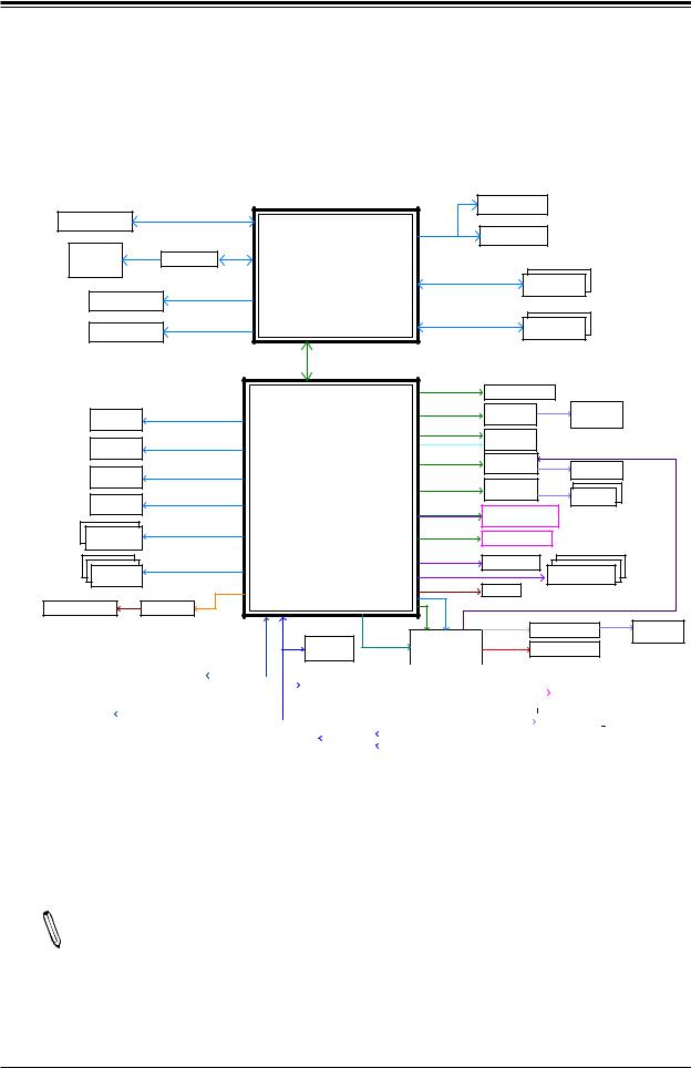
Figure 1-3.
System Block Diagram
|
|
PCIe3.0_x16/ PCIe3.0 x8x8 |
|
|
|
|
|
|
IMVP8-VGT |
INFINEON |
|
|
|||
PCIe x16 SLOT |
|
|
|
|
|
|
|
|
|
|
|
|
|||
|
8.0GT/s |
|
|
|
|
|
SVID |
|
|
|
|
|
|
||
|
|
|
|
|
|
|
|
IMVP8-Vcore |
INFINEON |
|
|
||||
|
|
|
|
|
|
|
|
|
|
|
|
||||
|
DVI-D |
TMDS |
ASM1442K |
DDI 1 |
INTEL LGA1200 |
DDR4 (CHA) |
DIMMA1 |
|
|
|
|||||
|
|
|
|
|
|
(Socket-H4) |
|
|
|
||||||
|
Display Port++ |
Digital port 3 |
DDI 3 |
|
2933MHzECC |
DIMMA2 |
|
|
|
||||||
|
|
|
|
|
|
|
|
|
|
|
|
|
|||
|
Display Port++ |
Digital port 2 |
|
|
|
|
|
DDR4 (CHB) |
DIMMB1 |
|
|
|
|||
|
DDI 2 |
|
|
|
|
2933MHzECC |
DIMMB2 |
|
|
|
|||||
|
|
|
|
|
|
|
|
|
|
||||||
|
|
|
|
|
|
|
|
|
|
|
|
|
|
||
|
|
|
|
|
|
x4 DMI |
|
|
|
|
|
|
|
|
|
|
|
|
|
|
|
8 GT/s |
|
|
|
|
|
|
|
|
|
|
|
|
|
|
|
|
|
PCIE[1:4] |
PCIe3.0 x4 |
PCIe x4 Slot 4 |
|
|
|
||
|
|
|
|
|
|
|
|
|
|
|
Rear I/O |
||||
|
USB3.2 |
|
Gen2 10 GT/s |
|
|
|
|
|
1250 Mbps-Phy |
GLAN1 |
MDI |
RJ45 |
|
||
Rear I/O |
|
USB 3.2[1] |
|
PCIE[5]-GbE |
|
|
|||||||||
|
|
|
I219LM |
|
|
1G-Base |
|
||||||||
Type-A |
|
|
USB 2.0[1] |
|
|
|
PCIe3.0 x1 |
|
|
|
|||||
|
|
|
|
|
PCIE[8] |
M.2 2230 |
|
|
|
|
|
||||
|
|
|
|
|
|
Intel |
|
|
|
|
|
|
|||
Rear I/O |
USB3.2 |
|
Gen2 10 GT/s |
|
|
|
|
|
|
|
|
|
|||
|
USB 3.2[2] |
|
CNVI |
|
E-Key |
|
|
|
|
Rear I/O |
|||||
|
Type-A |
|
|
USB 2.0[2] |
PCH-H |
|
PCIE[6] |
PCIe3.0 x1 |
GLAN2 |
MDI |
|
|
|||
|
|
|
|
|
|
|
RJ45 |
|
|
||||||
Rear I/O |
USB3.2 |
|
Gen2 10 GT/s |
USB 3.2[3] |
|
|
|
|
I210-AT |
|
|
|
|
||
|
|
|
|
|
GLAN3 |
|
|
1G-Base |
|
||||||
|
Type-A |
|
|
USB 2.0[3] W480E/Q470E |
PCIe3.0 x4 |
MDI |
RJ45x2 |
|
|
||||||
Rear I/O |
USB3.2 |
|
Gen2 10 GT/s |
|
|
|
PCIE[21-24] |
PCIe3.0 x4 |
X550-AT2 |
|
|
||||
|
USB 3.2[4] |
|
|
|
|
|
10G-Base |
|
|||||||
|
Type-A |
|
|
USB 2.0[4] |
|
|
|
SATA 6 Gb/s |
M.2 2280/22110 — x2 and x4 PCIe* NVMe SSD |
|
|||||
|
|
|
|
|
|
|
PCIE[17:20] |
|
M-Key |
|
— x2 and x4 Next Generation IntelR Optane Memory |
||||
|
USB3.2x2 |
Gen2 10 GT/s |
USB 3.2[5:6] |
|
|
SATA[4] |
|
|
|
|
|
|
|||
Internal Header |
|
|
|
PCIe3.0 x4 |
PCIe x4 Slot 7 |
IntelR Rapid Storage Technology |
|
||||||||
|
USB 2.0[5:6] |
|
|
PCIE[9-12] |
— x2 and x4 PCIe* NVMe SSD |
|
|
||||||||
Type-A |
|
|
|
|
|
— x2 and x4 Next Generation IntelR Optane Memory |
|||||||||
|
|
|
|
|
|
|
|
|
|
|
|
|
|
|
|
Internal Header |
USB2.0 |
480 MT/s |
USB 2.0[7:12] |
|
|
SATA[0B] |
SATA 6 Gb/s |
SATA-DOM |
SATA*3 Conn. |
|
|||||
|
|
SATA[1B:3] |
SATA 6 Gb/s |
|
|
|
|||||||||
|
x6 |
|
|
|
|
|
|
SGPIO |
|
|
|
|
|
||
|
|
|
|
SMBDAT/CLK_RSM |
USB 2.0[13] |
|
|
|
|
|
|
||||
|
|
|
|
|
|
|
NC-SI |
|
|
|
|
|
|||
8 bit-GPIO P/H |
PCA9554 |
|
SPI |
|
eSPI |
PCIE[7] |
|
|
|
|
|
||||
|
|
|
|
|
|
|
|
|
|
|
|
||||
|
|
|
|
|
|
|
|
|
|
RGMII |
RTL8211F-CG |
MDI |
RJ45 |
||
|
|
|
|
|
|
80 Port |
|
|
BMC |
|
|
1G-Base |
|||
|
|
|
|
|
|
|
|
RGB |
|
|
|
|
|||
|
|
|
|
|
|
|
|
VGA Conn. |
|
|
|||||
|
|
|
|
|
|
TPM P/H |
|
|
AST2500 |
|
|
|
|||
|
|
|
|
|
HD-A |
|
|
|
|
|
|
|
|
|
|
|
|
|
|
|
|
|||
|
Realtek ALC888S-VD2 |
|
|
|
|
|
|
|
|
|
|
|
|
|
|
|
|
|||||||
|
|
|
|
|
TPM 2.0 |
|
|
|
|
|
|
|
|
PWM , TACH |
|
|
|
|||||||
|
|
|
|
|
|
|
|
|
SLB9670VQ20FW785 |
|
|
|
|
|
|
FAN1~4, A,B |
||||||||
|
|
|
|
|
|
|
|
|
|
|
|
|
|
|
|
|
|
|
|
|
|
|
||
|
|
|
|
|
|
|
|
|
|
|
|
|
|
|
|
|
|
|
|
|
|
|||
|
|
|
|
|
|
|
|
|
|
|
|
|
|
|
|
|
|
|
|
|
|
|
|
|
Audio FP |
|
|
|
|
|
|
|
|
|
|
|
|
|
|
|
|
UART |
|
|
|
|
|||
|
|
|
|
|
|
|
|
|
|
|
CS0# |
|
|
|
|
|
|
|
|
|
|
RS-232 *2 |
|
|
|
|
|
|
|
|
|
|
|
|
|
|
|
|
|
|
|
|
|
|
|
|
|||
|
|
|
|
|
|
|
FLASH |
|
|
SW |
|
|
|
|
|
|
|
|
|
|
|
|
||
|
|
|
|
|
|
SPI 256Mb |
|
|
|
|
|
|
|
|
|
|
|
|
|
|
||||
|
|
|
|
|
|
|
|
|
|
|
|
|
|
|
|
|
|
|
|
|
||||
|
|
|
|
|
|
|
|
|
|
|
|
|
|
|
|
|
|
|
|
|
|
|
|
|
Note 1: This is a general block diagram and may not exactly represent the features  on your motherboard. See the previous pages for the actual specifications of your motherboard.
Note 2: The dual 10G LAN ports are only available on -TLN4F.
17

Super X12SCZ-TLN4F/QF/F User's Manual
1.2 Processor and Chipset Overview
The X12SCZ series comes in different model variations with different CPU support. The
X12SCZ-TLN4F/F supports Intel® Xeon W-1200 series, 10th Generation Core i9/i7/i5/i3, Pentium, and Celeron processors in an LGA1200 socket, while the X12SCZ-QF supports Intel 10th Generation Core i9/i7/i5/i3, Pentium, and Celeron processors in an LGA1200 socket. The X12SCZ-TLN4F/F features the W480E chipset and support for ECC and Non-ECC DDR4 UDIMM memory, while the X12SCZ-QF features the Q470E chipset and support for Non-ECC only. The X12SCZ series motherboards include the PCI Express 3.0 interface, four SATA 3.0 ports, IPMI 2.0, 12V DC power source, GPU add-on card power connector, dual 10GbE LAN option, HD Graphic outputs, and a combination of USB 2.0 and 3.2 ports. The motherboards also provide security-enhancing technologies such as Intel Software Guard Extensions (Intel SGX), Intel vPro, and Intel Trusted Execution Technology (TXT). The X12SCZ-TLN4F/QF/F offers exceptional system performance for entry server, data storage, network security, embedded applications, and cloud computing platforms.
The Intel PCH W480E chipset in conjunction with the new Intel Xeon W-1200 series processor, and the Intel Q470E chipset in conjunction with the new Intel 10th Gen. Core i series supports the following features:
•Intel Rapid Storage Technology
•Intel Rapid Storage Technology enterprise (Intel RST)
•Support for Management Engine (ME)
•Improved I/O capabilities to high-storage-capacity configurations
•Intel Virtualization Technology (Intel VT) and Trusted Execution Technology (Intel TXT)
•Intel Streaming SIMD Extensions 4.2 (Intel SSE4.2), Intel AVX2, and Advanced Encryption Standard New Instructions (Intel AES-NI)
•Intel 64 Architecture, Execute Disable Bit, Turbo Boost Technology 2.0, Hyper-Threading Technology (Intel HT Technology)
•PCI Express 3.0, SATA 3.0, USB 3.2
18

Chapter 1: Introduction
1.3 Special Features
Recovery from AC Power Loss
The Basic I/O System (BIOS) provides a setting that determines how the system will respond when AC power is lost and then restored to the system. You can choose for the system to remain powered off (in which case you must press the power switch to turn it back on), or for it to automatically return to the power-on state. See the Advanced BIOS Setup section for this setting. The default setting is Last State.
1.4 System Health Monitoring
This section describes the health monitoring features of the X12SCZ-TLN4F/QF/F motherboard. The motherboard has an onboard System Hardware Monitoring chip that supports system health monitoring.
Onboard Voltage Monitors
An onboard voltage monitor will scan the voltages of the onboard chipset, memory, CPU, and battery continuously. Once a voltage becomes unstable, a warning is given, or an error message is sent to the screen. The user can adjust the voltage thresholds to define the sensitivity of the voltage monitor.
Fan Status Monitor with Firmware Control
The system health monitor embedded in the BMC chip can check the RPM status of the cooling fans. The CPU and chassis fans are controlled via lPMI.
Environmental Temperature Control
System Health sensors monitor temperatures and voltage settings of onboard processors and the system in real time via the IPMI interface. Whenever the temperature of the CPU or the system exceeds a user-defined threshold, system/CPU cooling fans will be turned on to prevent the CPU or the system from overheating.
Note: To avoid possible system overheating, please be sure to provide adequate air-  flow to your system.
19

Super X12SCZ-TLN4F/QF/F User's Manual
System Resource Alert
This feature is available when used with SuperDoctor 5® in the Windows OS or in the Linux environment. SuperDoctor is used to notify the user of certain system events. For example, you can configure SuperDoctor to provide you with warnings when the system temperature, CPU temperatures, voltages and fan speeds go beyond a predefined range.
1.5 ACPI Features
ACPI stands forAdvanced Configuration and Power Interface. TheACPI specification defines a flexible and abstract hardware interface that provides a standard way to integrate power management features throughout a computer system, including its hardware, operating system and application software. This enables the system to automatically turn on and off peripherals such as CD-ROMs, network cards, hard disk drives and printers.
In addition to enabling operating system-directed power management, ACPI also provides a generic system event mechanism for Plug and Play, and an operating system-independent interface for configuration control. ACPI leverages the Plug and Play BIOS data structures, while providing a processor architecture-independent implementation that is compatible with appropriate Windows operating systems. For detailed information regarding OS support, please refer to the Supermicro website.
1.6 Power Supply
As with all computer products, a stable power source is necessary for proper and reliable operation. It is even more important for processors that have high CPU clock rates where noisy power transmission is present.
This motherboard accommodates a 24-pin ATX power supply. Although most power supplies generally meet the specifications required by the CPU, some are inadequate. In addition, one
12V 8-pin power connection is also required to ensure adequate power supply to the system.
Warning: To avoid damaging the power supply or the motherboard, be sure to use a power supply that contains a 24-pin and an 8-pin power connector. Be sure to connect the power supplies to the 24-pin power connector (JPW1), and the 8-pin power connector (JPV1) on the motherboard. Failure in doing so may void the manufacturer warranty on your power supply and motherboard.
Note 1: The X12SCZ Series motherboard alternatively supports an 8-pin 12V DC  input power only at JPV1 for embedded applications. The 12V DC input is limited to 30A by design. It provides up to 360W power input to the motherboard. Please keep the onboard power usage within the power limits specified above. Overcurrent power
usage may cause damage to the motherboard.
20
Chapter 1: Introduction
Note 2: Please connect both the 8-pin DC power at JPV1 to make sure the CPU re-  ceives enough power for normal operation when using the ATX power supply.
It is strongly recommended that you use a high quality power supply that meets ATX power supply Specification 2.02 or above. It must also be SSI compliant. (For more information, please refer to the website at http://www.ssiforum.org/).
1.7 Serial Port
This motherboard supports two serial communication connections. COM headers 1 and 2 can be used for input/output. The UART provides legacy speeds with a baud rate of up to 115.2 Kbps as well as an advanced speed with baud rates of 250 K, 500 K, or 1 Mb/s, which support high-speed serial communication devices.
21

Super X12SCZ-TLN4F/QF/F User's Manual
Chapter 2
Installation
2.1 Static-Sensitive Devices
Electrostatic Discharge (ESD) can damage electronic components. To avoid damaging your system board, it is important to handle it very carefully. The following measures are generally sufficient to protect your equipment from ESD.
Precautions
•Use a grounded wrist strap designed to prevent static discharge.
•Touch a grounded metal object before removing the board from the antistatic bag.
•Handle the motherboard by its edges only; do not touch its components, peripheral chips, memory modules or gold contacts.
•When handling chips or modules, avoid touching their pins.
•Put the motherboard and peripherals back into their antistatic bags when not in use.
•For grounding purposes, make sure that your computer chassis provides excellent conductivity between the power supply, the case, the mounting fasteners and the motherboard.
•Use only the correct type of onboard CMOS battery. Do not install the onboard battery upside down to avoid possible explosion.
Unpacking
The motherboard is shipped in antistatic packaging to avoid static damage. When unpacking the motherboard, make sure that the person handling it is static protected.
22
Chapter 2: Installation
2.2 Processor and Heatsink Installation
Warning: When handling the processor package, avoid placing direct pressure on the label area of the fan.
 Important:
•Use ESD protection.
•Unplug the AC power cord from all power supplies after shutting down the system.
•Check that the plastic protective cover is on the CPU socket and none of the socket pins are bent. If they are, contact your retailer.
•When handling the processor, avoid touching or placing direct pressure on the LGA lands (gold contacts). Improper installation or socket misalignment can cause serious damage to the processor or CPU socket, which may require manufacturer repairs.
•Thermal grease is pre-applied on a new heatsink. No additional thermal grease is needed.
•Refer to the Supermicro website for updates on processor support.
•All graphics in this manual are for illustrations only. Your components may look different.
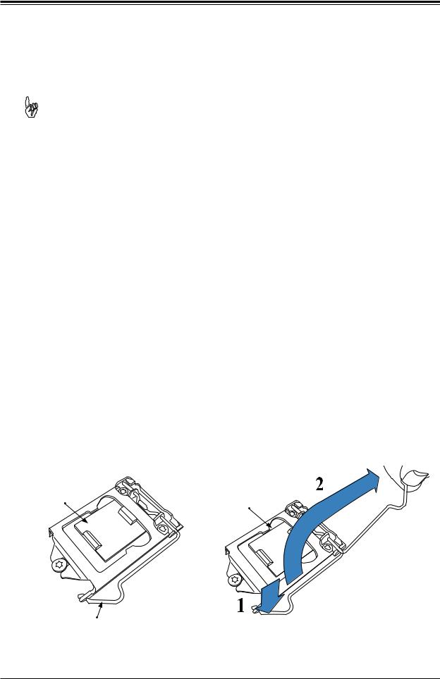
Installing the LGA1200 Processor
1. Press the load lever down to release the load plate from its locking position.
Plastic Protective |
Load Plate |
Cover |
Load Lever
23
Super X12SCZ-TLN4F/QF/F User's Manual
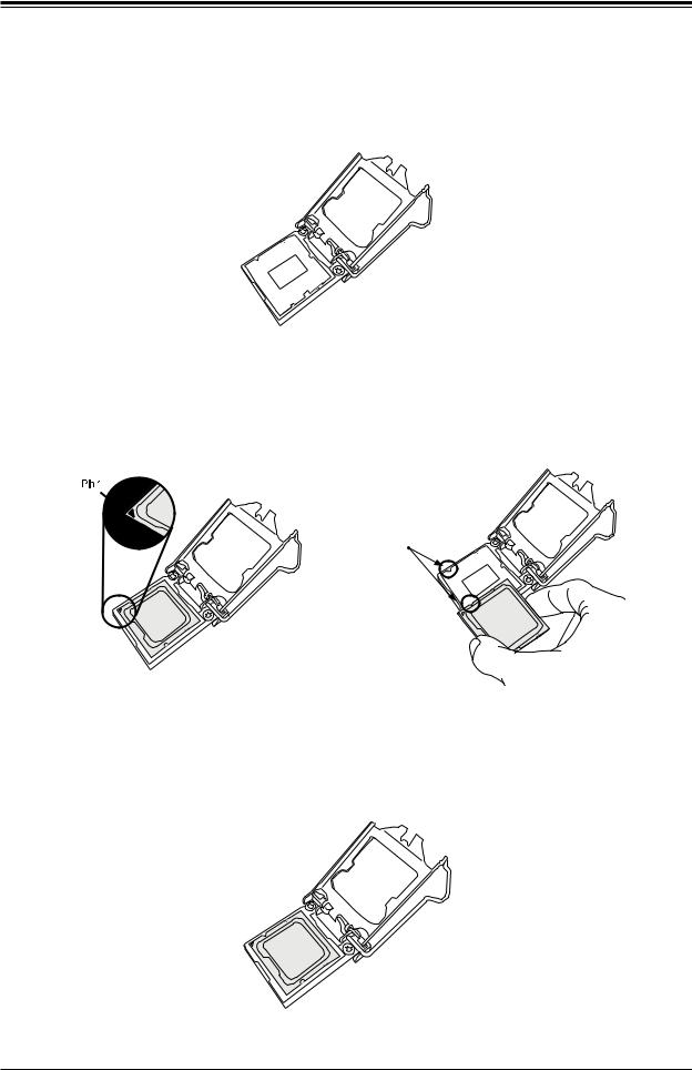
2.Gently lift the load lever to open the load plate. Remove the plastic protective cover. Do not touch the CPU socket contacts.
3.Locate the triangle on the CPU and CPU socket, which indicates the location of Pin 1.
Holding the CPU by the edges with your thumb and index finger, align the triangle on the CPU with the triangle on the socket. The CPU keys (the semi-circle cutouts) may also be aligned against the socket keys as a guide.
CPU / Socket Keys
4.Carefully lower the CPU straight down into the socket. Do not drop the CPU on the socket, or move it horizontally or vertically to avoid damaging the CPU or socket. Inspect the four corners of the CPU to make sure that the CPU is properly installed.
24
Chapter 2: Installation
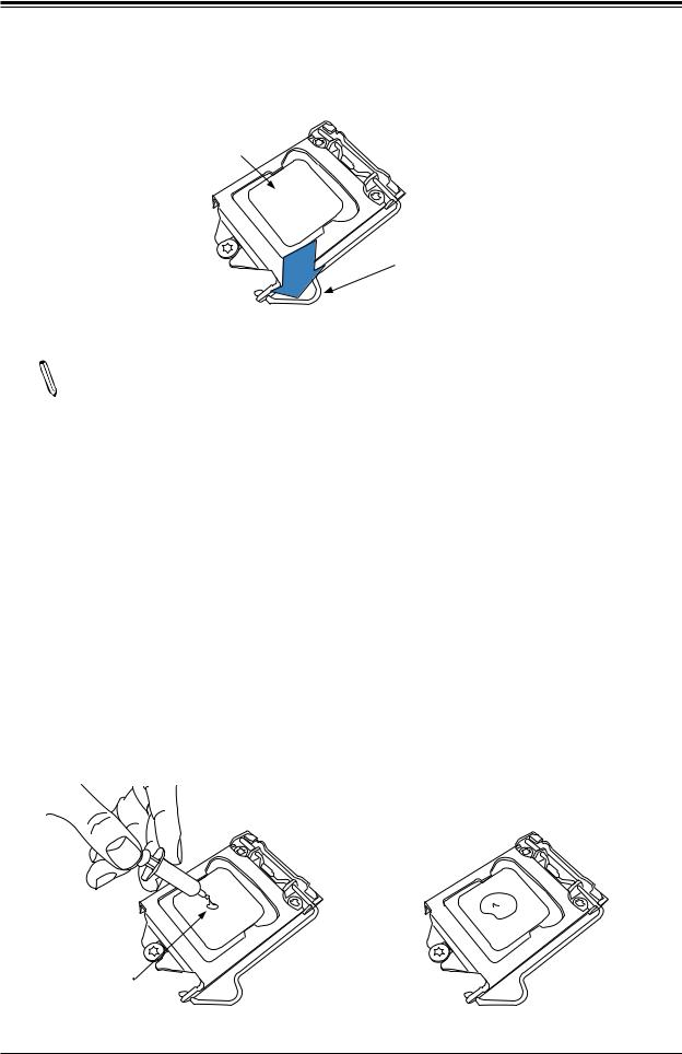
5. Close the load plate, then gently push down the load lever into its locking position.
CPU properly installed 
Load lever locked  into place
Note: You can only install the CPU in one direction. Make sure it is properly inserted into the socket before closing the load plate. If it doesn't close properly, do not force it as it may damage your CPU. Instead, open the load plate again and double-check that the CPU is properly aligned.
Installing an Active CPU Heatsink with Fan
1.Locate the CPU fan header on the motherboard (FAN1: CPU FAN).
2.Position the heatsink so that the heatsink fan wires are closest to the CPU fan header and are not interfering with other components.
3.Inspect the CPU fan wires to make sure they are routed through the bottom of the heatsink.
4.Remove the thin layer of protective film from the heatsink. CPU overheating may occur if the protective film is not removed from the heatsink.
5.Apply the proper amount of thermal grease on the CPU. If your heatsink came with a thermal pad, please ignore this step.
Thermal Grease
25
Super X12SCZ-TLN4F/QF/F User's Manual
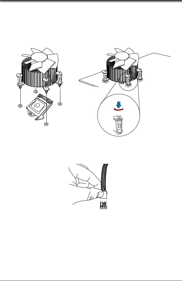
6.Align the four heatsink fasteners with the mounting holes on the motherboard. Gently push down the fasteners in a diagonal order (Example: #1 and #2, then #3 and #4) into the mounting holes until you hear a click. Then lock the fasteners by turning each one 90° clockwise.
2
4
3
 1
1
Push down
Lock
 Unlock
7.Once all four fasteners are secured, connect the heatsink fan wire connector to the CPU fan header.
26
Chapter 2: Installation
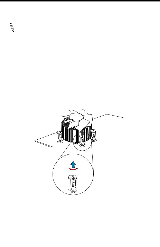
Removing the Heatsink
Note: We do not recommend that the CPU or heatsink be removed. However, if you  do need to remove the heatsink, please follow the instructions below to remove the
heatsink and prevent damage done to the CPU or other components.
1.Unplug the power connector from the power supply.
2.Disconnect the heatsink fan connector from the CPU fan header.
3.Gently press down each fastener cap and turn them 90°counter clockwise, then pull the fasteners upwards to loosen them.
4.Remove the heatsink from the CPU.
Pull up
Lock
 Unlock
27
Super X12SCZ-TLN4F/QF/F User's Manual
2.3 Motherboard Installation
All motherboards have standard mounting holes to fit different types of chassis. Make sure that the locations of all the mounting holes for both the motherboard and the chassis match. Although a chassis may have both plastic and metal mounting fasteners, metal ones are highly recommended because they ground the motherboard to the chassis. Make sure that the metal standoffs click in or are screwed in tightly.
Tools Needed
Phillips |
Phillips Screws |
Standoffs (8) |
Screwdriver |
(8) |
Only if Needed |
(1) |
|
|
AUDIO FP |
MH8 |
LED1UID |
SWUID |
|
|
MH4 |
|
|
|
|
DP++1/2 |
|
|
JBM1 |
|
JPAC1 |
|
|
|
COM1/2 |
PCH |
|
X8) (IN X4 0.3 PCIe SLOT4 |
||
JIPMB1 |
||
J18 |
|
|
JPME2 |
||
JGP1 |
|
|
JTPM1 |
JPG1 |
|
JPT1 |
||
USB10/11 (3.2 10Gb)
MH1
SLT4JPCIE |
SRW4 |
LED1HB BMC |
|
|
SRW2
CODE BAR
CODE SAN
ART1
JMD2
JPCIE6
X16 0.3 PCIe SLOT6 CPU
CODE BAR
|
SLT7 JPCIE SLOT7 PCH |
|
|
|
|
X4 0.3 PCIe |
|
|
JPTG1 J10G |
|
|
JPL1 |
JPL2 |
PWR |
|
|
|
||
|
|
JPL3/4:LAN3/4 |
|
|
|
|
1-2:ENABLE |
|
|
|
|
2-3:DISABLE |
|
|
|
BT1 |
|
|
|
|
+ |
|
|
|
|
BAR |
BAR |
|
|
BIOS LICENSE |
CODE |
CODE |
|
|
-I |
|
|
|
|
|
SATA3 |
|
|
|
|
MH5 |
|
|
|
|
|
|
-I |
|
|
Intel |
|
BAR |
SATA2 |
|
JBT1 |
W480/Q470 |
||
|
|
|
|
||
SATA1-I |
SP1 |
|
|
|
CODE |
|
|
|
|
|
|
|
I-SGPIO1 |
|
JSMB1 JD1 |
I-SATA0 |
|
|
|
|
JPWR1 |
FANB |
JL1 |
JMD1 |
|
FANA |
|||
|
|
SRW3 |
|
|
JSD1 |
|
|
JWD1 |
|
|
|
|
|
JRF1 |
|
MH7 |
|
|
|
|
|
||
USB0/1 |
USB2/3 |
USB4/5 |
DVI-D/VGA
JLAN1/2
JLAN3/4
JBM2
JVRM1
FAN4
USB6/7 (3.2 10G)
IPMI_LAN USB8/9(3.2 10G) 


MH3 


 JPW1 JPV1
X12SCZ-QF
REV:1.01
DESIGNED IN USA
|
|
|
|
|
|
|
|
|
|
|
|
|
|
|
|
|
|
|
|
|
|
|
|
|
|
|
|
|
|
|
|
JF1: |
|
|
|
|
|
|
|
|
|
|
|
|
|
|
ON |
|
RST |
FF |
NIC2 |
NIC1 |
LED |
LED |
NMI |
|
|
|
|
|
|
PWR |
|
OHX |
HDD |
PWR |
|
|
|
|
||||
|
|
|
|
|
|
|
|
|
|
|
LED1 |
|
FAN3 |
|
|
|
|
|
|
|
|
|
JF1 |
|
|
|
|||
|
|
|
|
|
|
|
|
|
|
|
|
|
|
|
DIMMB2
DIMMB1
DIMMA2
DIMMA1
MH2
JPH1


 JPI2C1 FAN1
 MH6 FAN2


Location of Mounting Holes
Note: 1) To avoid damaging the motherboard and its components, please do not use a force greater than 8 lbf-in on each mounting screw during motherboard installation. 2) Some components are very close to the mounting holes. Please take precautionary measures to avoid damaging these components when installing the motherboard to the chassis.
28
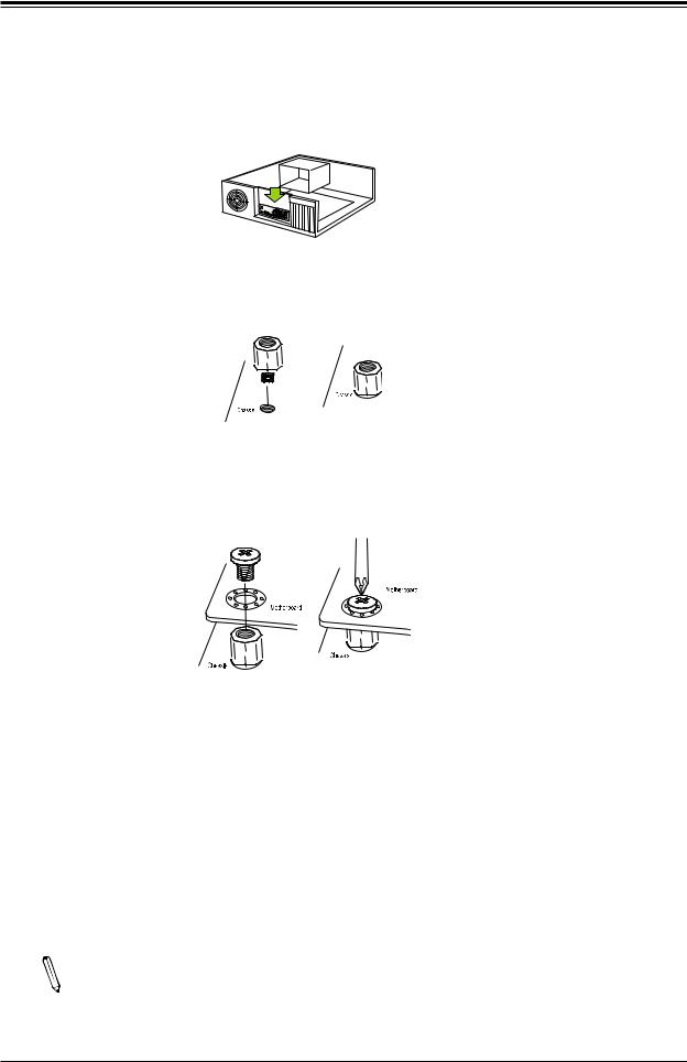
Chapter 2: Installation
Installing the Motherboard
1.Install the I/O shield into the back of the chassis, if applicable.
2.Locate the mounting holes on the motherboard. See the previous page for the location.
3.Locate the matching mounting holes on the chassis. Align the mounting holes on the motherboard against the mounting holes on the chassis.
4.Install standoffs in the chassis as needed.
5.Install the motherboard into the chassis carefully to avoid damaging other motherboard components.
6.Using the Phillips screwdriver, insert a pan head #6 screw into a mounting hole on the motherboard and its matching mounting hole on the chassis.
7.Repeat Step 5 to insert #6 screws into all mounting holes.
8.Make sure that the motherboard is securely placed in the chassis.
Note: Images displayed are for illustration only. Your chassis or components might  look different from those shown in this manual.
29
Super X12SCZ-TLN4F/QF/F User's Manual
2.4 Memory Support and Installation
Note: Check the Supermicro website for recommended memory modules. Important: Exercise extreme care when installing or removing DIMM modules to prevent any possible damage.
Memory Support
The X12SCZ-TLN4F/F supports up to 128GB of ECC or Non-ECC DDR4 UDIMM memory with speeds of up to 2933MHz in four memory slots. The X12SCZ-QF does not support ECC memory. Refer to the tables below for the recommended DIMM population order and additional memory information.
DIMM Module Population Configuration
For optimal memory performance, follow the table below when populating memory.
Recommended Population (Balanced)
DIMMA1 |
DIMMB1 |
DIMMA2 |
DIMMB2 |
Total System Memory |
|
|
|
|
|
|
|
4GB |
4GB |
8GB |
|
|
|
|
|
4GB |
4GB |
4GB |
4GB |
16GB |
|
|
|
|
|
|
|
8GB |
8GB |
16GB |
|
|
|
|
|
8GB |
8GB |
8GB |
8GB |
32GB |
|
|
|
|
|
|
|
16GB |
16GB |
32GB |
|
|
|
|
|
16GB |
16GB |
16GB |
16GB |
64GB |
|
|
|
|
|
|
|
32GB |
32GB |
64GB |
|
|
|
|
|
32GB |
32GB |
32GB |
32GB |
128GB |
|
|
|
|
|
30
Loading...