


 X8SIL
X8SIL


 X8SIL-F


 X8SIL-V
USER’S MANUAL
Revision 1.2a

The information in this User’s Manual has been carefully reviewed and is believed to be accurate. The vendor assumes no responsibility for any inaccuracies that may be contained in this document, makes no commitment to update or to keep current the information in this manual, or to notify any person or organization of the updates. Please Note: For the most up-to-date version of this manual, please see our web site at www.supermicro.com.
Super Micro Computer, Inc. ("Supermicro") reserves the right to make changes to the product described in this manual at any time and without notice. This product, including software and documentation, is the property of Supermicro and/or its licensors, and is supplied only under a license. Any use or reproduction of this product is not allowed, except as expressly permitted by the terms of said license.
IN NO EVENT WILL SUPER MICRO COMPUTER, INC. BE LIABLE FOR DIRECT, INDIRECT, SPECIAL, INCIDENTAL, SPECULATIVE OR CONSEQUENTIAL DAMAGES ARISING FROM THE USE OR INABILITY TO USE THIS PRODUCT OR DOCUMENTATION, EVEN IF ADVISED OF THE POSSIBILITY OF SUCH DAMAGES. IN PARTICULAR, SUPER MICRO COMPUTER, INC. SHALL NOT HAVE LIABILITY FOR ANY HARDWARE, SOFTWARE, OR DATA STORED OR USED WITH THE PRODUCT, INCLUDING THE COSTS OF REPAIRING, REPLACING, INTEGRATING, INSTALLING OR RECOVERING SUCH HARDWARE, SOFTWARE, OR DATA.
Any disputes arising between manufacturer and customer shall be governed by the laws of Santa Clara County in the State of California, USA. The State of California, County of Santa Clara shall be the exclusive venue for the resolution of any such disputes. Supermicro's total liability for all claims will not exceed the price paid for the hardware product.
FCC Statement: This equipment has been tested and found to comply with the limits for a Class A digital device pursuant to Part 15 of the FCC Rules. These limits are designed to provide reasonable protection against harmful interference when the equipment is operated in a commercial environment. This equipment generates, uses, and can radiate radio frequency energy and, if not installed and used in accordance with the manufacturer’s instruction manual, may cause harmful interference with radio communications. Operation of this equipment in a residential area is likely to cause harmful interference, in which case you will be required to correct the interference at your own expense.
California Best Management Practices Regulations for Perchlorate Materials: This Perchlorate warning applies only to products containing CR (Manganese Dioxide) Lithium coin cells. “Perchlorate Material-special handling may apply. See www.dtsc.ca.gov/hazardouswaste/perchlorate”.
WARNING: Handling of lead solder materials used in this product may expose you to lead, a chemical known to the State of California to cause birth defects and other reproductive harm.
Manual Revision 1.2a
Release Date: August 30, 2013
Unless you request and receive written permission from Super Micro Computer, Inc., you may not copy any part of this document.
Information in this document is subject to change without notice. Other products and companies referred to herein are trademarks or registered trademarks of their respective companies or mark holders.
Copyright © 2013 by Super Micro Computer, Inc. All rights reserved.
Printed in the United States of America
Preface
Preface
This manual is written for system integrators, PC technicians and knowledgeable PC users. It provides information for the installation and use of the 


 X8SIL/X8SIL-F/X8SIL-V motherboard.
About This Motherboard
The 


 X8SIL/X8SIL-F/X8SIL-V supports the Intel® Xeon® 3400 series processors in an LGA 1156 socket. With the Intel 3400/3420 chipset built-in, the X8SIL/ X8SIL-F/X8SIL-V offers substantial enhancements in price/system performance ratio in a cost-effective, small form-factor package. Please refer to our web site (http://www.supermicro.com/products/) for updates on supported processors. This product is intended to be installed and serviced by professional technicians.
Manual Organization
Chapter 1 describes the features, specifications and performance of the motherboard and provides detailed information about the chipset.
Chapter 2 provides hardware installation instructions. Read this chapter when installing the processor, memory modules and other hardware components into the system. If you encounter any problems, see Chapter 3, which describes troubleshooting procedures for video, memory and system setup stored in the CMOS.
Chapter 4 includes an introduction to the BIOS and provides detailed information on running the CMOS Setup utility.
Appendix A provides BIOS Error Beep Codes.
Appendix B lists Other Software Program Installation Instructions. Appendix C contains the BIOS Recovery Instructions.
Conventions Used in the Manual:
Special attention should be given to the following symbols for proper installation and to prevent damage done to the components or injury to yourself:
Danger/Caution: Instructions to be strictly followed to prevent catastrophic system failure or to avoid bodily injury
Warning: Important information given to ensure proper system installation or to prevent damage to the components
Note: Additional Information given to differentiate various models or provides information for correct system setup.
iii

Contacting Supermicro
Contacting Supermicro
Headquarters |
|
Address: |
Super Micro Computer, Inc. |
|
980 Rock Ave. |
|
San Jose, CA 95131 U.S.A. |
Tel: |
+1 (408) 503-8000 |
Fax: |
+1 (408) 503-8008 |
Email: |
marketing@supermicro.com (General Information) |
|
support@supermicro.com (Technical Support) |
Web Site: |
www.supermicro.com |
Europe |
|
Address: |
Super Micro Computer B.V. |
|
Het Sterrenbeeld 28, 5215 ML |
|
's-Hertogenbosch, The Netherlands |
Tel: |
+31 (0) 73-6400390 |
Fax: |
+31 (0) 73-6416525 |
Email: |
sales@supermicro.nl (General Information) |
|
support@supermicro.nl (Technical Support) |
|
rma@supermicro.nl (Customer Support) |
Asia-Pacific |
|
Address: |
Super Micro Computer, Inc. |
|
3F, No. 150, Jian 1st Rd. |
|
Zhonghe Dist., New Taipei City 23511 |
|
Taiwan (R.O.C) |
Tel: |
+886-(2) 8226-3990 |
Fax: |
+886-(2) 8226-3992 |
Web Site: |
www.supermicro.com.tw |
Technical Support: |
|
Email: |
support@supermicro.com.tw |
Tel: |
+886-(2)-8226-3990 |
v


 X8SIL/X8SIL-F/X8SIL-V User’s Manual
Table of Contents
Preface
Chapter 1 Introduction
1-1 |
Overview.......................................................................................................... |
1-1 |
1-2 |
Chipset Overview ......................................................................................... |
1-10 |
1-3 |
PC Health Monitoring..................................................................................... |
1-11 |
1-4 |
Power Configuration Settings......................................................................... |
1-11 |
1-5 |
Power Supply................................................................................................. |
1-12 |
1-6 |
Super I/O....................................................................................................... |
1-13 |
1-7 |
iSCSI Support................................................................................................ |
1-13 |
1-8 |
Overview of the Nuvoton BMC Controller..................................................... |
1-14 |
Chapter 2 Installation
2-1 |
Static-Sensitive Devices.................................................................................. |
2-1 |
|
Precautions...................................................................................................... |
2-1 |
|
Unpacking........................................................................................................ |
2-1 |
2-2 Processor and Heatsink Installation................................................................ |
2-2 |
|
|
Installing the LGA1156 Processor................................................................... |
2-2 |
|
Installing a Passive CPU Heatsink.................................................................. |
2-5 |
|
Removing the Heatsink................................................................................... |
2-6 |
|
Installing an Active Fan CPU Heatsink............................................................ |
2-7 |
2-3 |
Installing DDR3 Memory................................................................................ |
2-10 |
|
DIMM Installation........................................................................................... |
2-10 |
|
Memory Support............................................................................................ |
2-10 |
|
Memory Population Guidelines....................................................................... |
2-11 |
|
Installing and Removing DIMMs.................................................................... |
2-12 |
|
Tools Needed................................................................................................. |
2-14 |
|
Location of Mounting Holes........................................................................... |
2-14 |
2-4 |
Motherboard Installation................................................................................ |
2-14 |
|
Installation Instructions.................................................................................. |
2-15 |
2-5 |
Connectors/IO Ports...................................................................................... |
2-16 |
|
Back Panel Connectors and IO Ports........................................................... |
2-16 |
|
ATX PS/2 Keyboard and PS/2 Mouse Ports............................................ |
2-17 |
|
Universal Serial Bus (USB)...................................................................... |
2-18 |
|
Ethernet Ports........................................................................................... |
2-19 |
|
Serial Ports............................................................................................... |
2-20 |
|
Video Connector....................................................................................... |
2-21 |
|
Front Control Panel....................................................................................... |
2-22 |
vi

|
|
Table of Contents |
|
|
|
|
|
|
|
Front Control Panel Pin Definitions............................................................... |
2-23 |
|
Power LED ............................................................................................... |
2-23 |
|
HDD LED.................................................................................................. |
2-23 |
|
NIC1/NIC2 (LAN1/LAN2).......................................................................... |
2-24 |
|
Overheat (OH)/Fan Fail............................................................................ |
2-24 |
|
Reset Button ............................................................................................ |
2-25 |
|
Power Button ........................................................................................... |
2-25 |
2-6 |
Connecting Cables........................................................................................ |
2-26 |
|
ATX Main PWR & CPU PWR Connectors .............................................. |
2-26 |
|
Fan Headers............................................................................................. |
2-27 |
|
Chassis Intrusion ..................................................................................... |
2-27 |
|
Internal Buzzer.......................................................................................... |
2-28 |
|
Speaker..................................................................................................... |
2-28 |
|
TPM Header.............................................................................................. |
2-28 |
|
Onboard Power LED................................................................................. |
2-29 |
|
Power Supply I2C Connector.................................................................... |
2-29 |
|
DOM PWR Connector............................................................................... |
2-29 |
|
T-SGPIO 0/1 Headers............................................................................... |
2-30 |
2-7 |
Jumper Settings............................................................................................. |
2-31 |
|
Explanation of Jumpers................................................................................. |
2-31 |
|
LAN Port Enable/Disable.......................................................................... |
2-31 |
|
CMOS Clear.............................................................................................. |
2-32 |
|
PCI Slot SMB Enable............................................................................... |
2-32 |
|
VGA Enable.............................................................................................. |
2-33 |
|
Energy Saving Enable.............................................................................. |
2-33 |
|
USB Wake-Up .......................................................................................... |
2-34 |
|
BMC Enable.............................................................................................. |
2-34 |
2-8 |
Onboard Indicators........................................................................................ |
2-35 |
|
LAN 1/LAN 2 LEDs................................................................................... |
2-35 |
|
IPMI Dedicated LAN LEDs ...................................................................... |
2-35 |
|
Onboard Power LED ............................................................................................................. |
2-36 |
|
IPMI Heartbeat LED (X8SIL-F Only)........................................................ |
2-36 |
|
Unsupported Memory LED....................................................................... |
2-36 |
2-9 SATA and Floppy Drive Connections............................................................ |
2-37 |
|
|
SATA Connections.................................................................................... |
2-37 |
|
Floppy Connector...................................................................................... |
2-38 |
Chapter 3 Troubleshooting |
|
|
3-1 |
Troubleshooting Procedures............................................................................ |
3-1 |
3-2 |
Technical Support Procedures......................................................................... |
3-2 |
vii


 X8SIL/X8SIL-F/X8SIL-V User’s Manual
3-3 |
Frequently Asked Questions............................................................................ |
3-3 |
3-4 |
Battery Removal and Installation..................................................................... |
3-6 |
3-5 |
Returning Merchandise for Service................................................................. |
3-7 |
Chapter 4 BIOS
4-1 |
Introduction...................................................................................................... |
4-1 |
4-2 |
Main Setup....................................................................................................... |
4-2 |
4-3 |
Advanced Setup Configurations...................................................................... |
4-4 |
4-4 |
Security Settings............................................................................................ |
4-22 |
4-5 |
Boot Settings................................................................................................. |
4-23 |
4-6 |
Exit Options................................................................................................... |
4-24 |
Appendix A POST Error Beep Codes |
|
|
Recoverable POST Error Beep Codes....................................................................... |
A-1 |
|
Appendix B Software Installation Instructions |
|
|
B-1 |
Installing Drivers.............................................................................................. |
B-1 |
B-2 |
Configuring SuperDoctor® III.......................................................................... |
B-2 |
Appendix C BIOS Recovery |
|
|
C-1 Recovery Process from a USB Device/Drive (Recommended Method)............. |
C-1 |
|
C-2 Recovery Process from an IDE/SATA ATAPI Disc Drive..................................... |
C-2 |
|
viii

Chapter 1: Introduction
Chapter 1
Introduction
1-1 Overview
Checklist
Congratulations on purchasing your computer motherboard from an acknowledged leader in the industry. Supermicro boards are designed with the utmost attention to detail to provide you with the highest standards in quality and performance.
Please check that the following items have all been included with your motherboard. If anything listed here is damaged or missing, contact your retailer.
The following items are included in the retail box.
•One (1) Supermicro Mainboard
•Six (6) SATA cables (CBL-0044L)
•One (1) floppy drive ribbon cable (CBL-022L)
•One (1) I/O shield (MCP-260-00027-ON)
•One (1) Supermicro CD containing drivers and utilities (CDR-X8-UP)
•One (1) User's Manual (MNL-1130)
1-1


 X8SIL/X8SIL-F/X8SIL-V User’s Manual


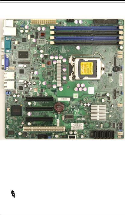
 Motherboard Image (X8SIL-F Shown)
Note: All graphics shown in this manual were based upon the latest PCB Revision available at the time of publishing of the manual. The motherboard you've received may or may not look exactly the same as the graphics shown in this manual.
1-2
|
|
|
Chapter 1: Introduction |
|
|
|
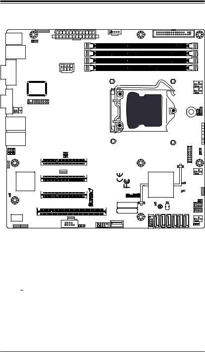
Motherboard Layout |
|
|
KB/MOUSE |
JPUSB1:B/P USB WAKE UP |
JPI2C:PWR I2C |
JPI2C |
|
2-3:DISABLE |
|
|
||
|
1-2:ENABLE |
|
|
|
|
|
|
FLOPPY |
requiredUDIMM/RDIMM1066/1333DDR3 |
COM1 |
1 |
JPW1 |
DIMM1BDIMM2ADIMM2BDIMM1A |
|
|
JPUSB1 |
|
|
|
VGA |
|
1 |
FAN5 |
LAN1
JLAN2 JLAN1
JPB 1 |
JPL11 |
JPL21 |
JPB:BMC 1-2:ENABLE 2-3:DISABLE |
|
|
LE7 |
|
|
U61
JPL2:LAN2 JPL1:LAN1 1-2:ENABLE 1-2:ENABLE 2-3:DISABLE 2-3:DISABLE
|
|
FAN1 |
|
|
|
|
FAN2 |
|
|
JTPM |
|
U26 |
JLED1:Power LED |
JD1:Buzzer/Speaker |
|
|
|
1 |
1 |
|
|
SPKR1 |
JLED1 |
JD1 |
|
|
|
|
PWR LED |
|
|
|
|
HDD LED |
|
|
|
|
NIC1 |
|
|
CPU |
|
NIC2 |
|
|
|
OH/FF |
|
|
|
|
|
X |
|
|
|
|
RST |
|
|
|
|
PWR ON |
JI2C1 |
1 |
JF1 |
|
1 JPES |
JI2C2 1 |
|
|
|
|
J6 |
SLOT7 PCI-E X8 GEN2 |
JI2C1/JI2C2
ON:Enable
OFF:Disable
J5 |
SLOT6 PCI-E X8 GEN2 |
J8 |
|
|
REV:1.00 |
USA |
|
SLOT5 PCI-E X4 on X8 |
|
|
IN |
|
|
|
X8SIL DESIGNED |
|
|||
SLOT4 PCI 33MHZ |
|
MAC CODE |
|||
|
|
|
|
|
BAR CODE |
|
JPG1: VGA |
|
|
|
|
|
1-2:Enable |
|
|
|
|
J16 |
2-3:Disable |
JL1:CHASSIS INTRUSION |
USB 10/11 |
J24 |
|
COM2 |
|
|
|||
|
JPG1 |
J14 |
|
USB4 |
|
|
|
|
|
|
|
LE4
LE3
U2
LE2 |
JBT1 |
|
JBT1:CMOS CLEAR
|
I-SATA5 |
I-SATA1 |
I-SATA3 |
||
J13 |
I-SATA4 |
I-SATA0 |
I-SATA2 |
||
USB2/3 |
1 |
|
FAN3 |
|
JPT1:TPM 1-2:Enable 2-3:Disable |
SGPIO2 |
JL1 |
T- |
|
T-SGPIO1 |
|
|
FAN4 |
DOM PWR
Important Notes to the User
•See Chapter 2 for detailed information on jumpers, I/O ports and JF1 front panel connections.
•"  " indicates the location of "Pin 1".
•Jumpers not indicated are for testing only.
•When LE2 (Onboard Power LED Indicator) is on, system power is on. Unplug the power cable before installing or removing any components.
1-3


 X8SIL/X8SIL-F/X8SIL-V User’s Manual
1 |
1 |
1 |
1 |
1 |
38 |
37 |
36 |
35 |
34 |
|
KB/MOUSE |
JPUSB1:B/P USB WAKE UP |
JPI2C:PWR I2C |
JPI2C |
|
2:ENABLE |
|||
|
12--3:DISABLE |
|||
1 |
|
|
|
|
|
|
|
FLOPPY |
|
|
1 |
JPW1 |
|
|
1 |
|
JPUSB1 |
|
|
2 |
|
|
|
|
|
|
|
|
|
1 |
|
|
|
|
3 |
|
|
|
|
1 |
COM1 |
|
|
|
4 |
|
|
|
|
|
|
|
|
|
1 |
|
|
|
|
16 

17
18
19
101
111
121
131
141
151
1 VGA
JPB 1 |
JPL11 |
JPL21 |
JPB:BMC 1-2:ENABLE 2-3:DISABLE |
|
|
LE7 |
|
|
|
U61 |
|
JPL2:LAN2 1-2:ENABLE 2-3:DISABLE
FAN5
LAN1
JLAN2 JLAN1
JPL1:LAN1 1-2:ENABLE 2-3:DISABLE
|
39 |
JTPM |
1 |
JI2C1 1
JI2C2 1
J6 |
SLOT7 PCI-E X8 GEN2 |
CPU
401
411
JI2C1/JI2C2
ON:Enable
OFF:Disable
J5 |
SLOT6 PCI-E X8 GEN2 |
J8 |
|
|
REV:1.00 |
USA |
|
SLOT5 PCI-E X4 on X8 |
|
|
IN |
|
|
|
X8SIL DESIGNED |
|
|||
SLOT4 PCI 33MHZ |
|
MAC CODE |
|||
|
|
|
|
|
BAR CODE |
|
JPG1: VGA |
|
|
|
|
|
1-2:Enable |
|
|
|
|
J16 |
2-3:Disable |
JL1:CHASSIS INTRUSION |
USB 10/11 |
J24 |
|
COM2 |
|
|
|
|
|
|
JPG1 |
J14 |
|
USB4 |
|
U26
|
|
|
|
|
1 |
|
|
|
|
|
43 |
JF1 |
|
|
|
|
|
|
|
|
|
|
1 |
|
|
|
|
|
|
42 |
|
|
|
LE4 |
|
|
|
|
|
|
LE3 |
U2 |
|
|
|
|
|
|
|
LE2 |
JBT1 |
|
|
|
|
|
|
|
|
|
|
|
JBT1:CMOS CLEAR |
|
|
|
|
||
|
I-SATA5 |
I-SATA1 |
I-SATA3 |
|||
J13 |
|
I-SATA4 |
I-SATA0 |
I-SATA2 |
||
USB2/3 |
1 |
|
|
|
|
|
1 |
1 |
1 |
1 |
1 |
1 |
16 |
17 |
18 |
19 |
20 |
21 |
|
|
DIMM1B DIMM1A DIMM2B DIMM2A DDR3 1066/1333 UDIMM/RDIMM required |
1 |
|
|
|
|
FAN2FAN1 |
|
|
33 |
|
|
1 |
|
|
|
|
32 |
|
|
JD1:Buzzer/Speaker |
1 |
|
JLED1:PowerLED |
31 |
|
|
1 |
||
|
1 |
1 |
30 |
SPKR1 |
JLED1 |
JD1 |
|
|
|
PWR LED |
|
|
|
HDD LED |
1 |
|
|
X |
|
|
|
NIC1 |
29 |
|
|
NIC2 |
|
|
|
OH/FF |
|
|
|
RST |
|
|
|
PWR ON |
|
|
|
JPES |
1 |
|
|
|
|
|
|
1 |
28 |
|
|
|
1 |
|
FAN3 |
|
27 |
|
|
1 |
|
|
|
|
|
|
|
|
26 |
|
|
JPT1:TPM 1-2:Enable 2-3:Disable |
1 |
|
|
|
|
SGPIO2 |
JL1 |
|
25 |
T- |
|
|
|
T-SGPIO1 |
|
|
|
|
|
FAN4 |
|
|
DOM PWR |
1 |
|
|
22 |
||
|
1 |
|
23 |
|
|
|
|
X8SIL/X8SIL-F/X8SIL-V Quick Reference
X8SIL/X8SIL-F/X8SIL-V Jumpers
Number |
Jumper |
Description |
Default |
|
38 |
JPUSB1 |
BP USB0/1 Wake-up |
Pins 1-2 (Enabled) |
|
|
|
|
|
|
42 |
JBT1 |
CMOS Clear |
(See Chpt. 2) |
|
|
|
|
|
|
40 |
JPES |
Energy Saving Feature |
Pins 2-3 |
(Disabled) |
|
|
|
|
|
13,14 |
JI2C1/JI2C2 |
SMB to PCI Slots |
(See Chpt. 2) |
|
17 |
JPG1 |
Onboard VGA Enable |
Pins 1-2 |
(Enabled) |
|
|
|
|
|
11,12 |
JPL1/JPL2 |
LAN1/LAN2 Enable |
Pins 1-2 |
(Enabled) |
10 |
JPB |
BMC Enable |
Pins 1-2 |
(Enabled) |
|
|
|
|
|
1-4

|
|
|
|
|
|
|
|
Chapter 1: Introduction |
|
|
|
|
|
|
|
|
|
|
|
|
|
|
|
|
|
|
|
|
|
|
|
|
|
|
|
|
|||
|
|
|
|
X8SIL/X8SIL-F/X8SIL-V Headers/Connectors |
|
||||
|
Number |
|
Connector |
Description |
|
|
|||
|
4,16 |
|
|
COM1/COM2 |
COM1/2 Serial connection headers |
|
|||
|
|
|
|
|
|
||||
|
33,32,27,23,7 |
|
Fans 1~5 |
System/CPU fan headers |
|
||||
|
|
|
|
|
|
|
|
||
|
34 |
|
|
Floppy |
|
Floppy Disk Drive connector |
|
||
|
|
|
|
|
|
|
|||
|
30 |
|
|
JD1 |
|
Speaker header (Pins 3/4: Internal, 1~4:External) |
|||
|
|
|
|
|
|
|
|
||
|
28 |
|
|
JF1 |
|
Front Panel Control header |
|
||
|
|
|
|
|
|
|
|
||
|
41 |
|
|
JL1 |
|
Chassis Intrusion header |
|
||
|
|
|
|
|
|
|
|
||
|
29 |
|
|
JLED |
|
Power LED Indicator header |
|
||
|
37 |
|
|
JPW1 |
|
24-pin ATX main power connector (required) |
|||
|
|
|
|
|
|
|
|||
|
36 |
|
|
JPW2 |
|
+12V 8-pin CPU power connector (required) |
|||
|
|
|
|
|
|
|
|||
|
1 |
|
|
KB/Mouse |
Keyboard/mouse connectors |
|
|||
|
|
|
|
|
|
||||
|
8,9 |
|
|
LAN1~LAN2, |
Gigabit Ethernet (RJ45) ports (LAN1/LAN2) |
||||
|
|
|
|
|
|
||||
|
21 |
|
|
I-SATA 0~5 |
Serial ATA ports (X8SIL has 4 Serial ATA Ports) |
||||
|
|
|
|
|
|
|
|||
|
2 |
|
|
IPMI LAN |
IPMI LAN Port (X8SIL-F Only) |
|
|||
|
|
|
|
|
|
|
|||
|
35 |
|
|
JPI2C |
|
PWR supply (I2C) System Management Bus |
|||
|
31 |
|
|
SPKR1 |
|
Internal speaker/buzzer |
|
||
|
|
|
|
|
|
||||
|
25 |
|
|
T-SGPIO-0/1 |
Serial General Purpose IO headers (for SATA) |
||||
|
|
|
|
|
|
||||
|
3,20 |
|
|
USB0/1, USB 2/3 |
Backpanel USB 0/1, Front panel accessible USB 2/3 |
||||
|
|
|
|
|
|
|
|
||
|
19 |
|
|
USB 4 |
|
Type A USB Connector |
|
||
|
|
|
|
|
|
||||
|
18 |
|
|
USB 10/11 |
Front Panel USB header (X8SIL-F/X8SIL-V Only) |
||||
|
|
|
|
|
|
||||
|
22 |
|
|
DOM PWR |
Disk-On-Module (DOM) Power Connector |
||||
|
|
|
|
|
|
|
|||
|
39 |
|
|
JTPM |
|
Trusted Platform Module (TPM) Header |
|||
|
|
|
|
|
|
|
|
||
|
6 |
|
|
VGA |
|
Onboard Video Port |
|
||
|
|
|
|
|
|
|
|
|
|
|
|
|
|
|
|
|
|
|
|
|
|
|
|
|
|
X8SIL/X8SIL-F/X8SIL-V LED Indicators |
|
||
|
Number |
|
LED |
|
Description |
|
Color/State |
Status |
|
|
|
|
|
|
|
|
|
|
|
|
43 |
|
LE3 |
|
Unsupported Memory Installed |
Yellow: Blinking |
Unsupported |
||
|
|
|
Indicator |
|
Memory Installed |
||||
|
|
|
|
|
|
|
|
||
|
|
|
|
|
|
|
|
|
|
|
26 |
|
LE4 |
|
Onboard Standby PWR LED |
Green: Solid on |
PWR On |
||
|
|
|
|
|
|
|
|
|
|
|
15 |
|
LE7 |
|
IPMI Heartbeat LED (X8SIL-F Only) |
Green: Blinking |
IPMI: Normal |
||
|
|
|
|
|
|
|
|
|
|
1-5


 X8SIL/X8SIL-F/X8SIL-V User’s Manual
Motherboard Features
CPU |
Single Intel® Xeon® 3400 series processor in an LGA1156 |
|||
|
socket. |
|
||
|
|
|
|
|
Memory |
Four (4) 240-pin, DDR3 SDRAM DIMM sockets with sup- |
|||
|
port for up to 16GB of UDIMM or up to 32GB of RDIMM |
|||
|
memory (ECC/DDR3 1333/1066/800 MHz memory only.) |
|||
|
|
|
|
|
|
Supports dual-channel memory bus |
|||
|
|
|
|
|
|
DIMM sizes |
|
||
|
UDIMM |
|
|
1 GB, 2 GB, and 4GB |
|
|
|
|
|
|
RDIMM |
|
|
1 GB, 2GB, 4GB, and 8GB |
|
|
|
|
|
Chipset |
Intel® 3420 Chipset (X8SIL-F/X8SIL-V) |
|||
|
Intel® 3400 Chipset (X8SIL) |
|||
|
|
|
|
|
Expansion Slots |
Two (2) PCI Express 2.0 (x8) slot |
|||
|
One (1) PCI Express x4 (x8) slot |
|||
|
|
|
|
|
|
One (1) 32-bit PCI 33MHz slot (5.0V on board revision 1.01 |
|||
|
and below, 3.3V on board revision 1.02 and above) |
|||
|
|
|
|
|
Integrated Graphics |
Matrox® G200eW |
|
||
Network Connections |
Two Intel 82574L Gigabit (10/100/1000 Mb/s) Ethernet |
|||
|
Controllers for LAN 1 and LAN 2 ports. |
|||
|
Two (2) RJ-45 Rear IO Panel Connectors with Link and |
|||
|
Activity LEDs |
|
||
|
Single Realtek RTL8201N PHY to support IPMI 2.0 |
|||
|
(X8SIL-F Only) |
|
||
I/O Devices |
SATA Connections (X8SIL-F/X8SIL-V Only) |
|||
|
SATA Ports |
|
Six (6) |
|
|
|
|
|
|
|
RAID (Windows) |
|
RAID 0, 1, 5, 10 |
|
|
|
|
|
|
|
RAID (Linux) |
|
RAID 0, 1, 10 |
|
|
|
|
|
|
|
SATA Connections (X8SIL Only) |
|||
|
SATA Ports |
Four (4) |
||
|
|
|
|
|
|
Integrated IPMI 2.0 (X8SIL-F Only) |
|||
|
IPMI 2.0 supported by the WPCM450 Server BMC |
|||
|
|
|
|
|
|
Floppy Disk Drive |
|
||
|
One (1) floppy drive interface (up to 1.44 MB) |
|||
|
|
|
|
|
|
USB Devices (X8SIL Only) |
|||
|
Two (2) USB ports on the rear IO panel |
|||
|
Two (2) USB header connectors for front access |
|||
|
|
|
||
|
One (1) Type A internal connector |
|||
1-6

|
Chapter 1: Introduction |
|
|
|
|
|
|
I/O Devices |
USB Devices (X8SIL-F/X8SIL-V Only) |
(Continued) |
|
|
Two (2) USB ports on the rear IO panel |
|
|
|
Four (4) USB header connectors for front access |
|
One (1) Type A internal connector |
|
|
|
Keyboard/Mouse |
|
PS/2 Keyboard/Mouse ports on the I/O backpanel |
|
|
|
Serial (COM) Ports |
|
Two (2) Fast UART 16550 Connections: one 9-pin RS-232 |
|
port and one header |
|
Super I/O |
|
Winbond Super I/O 83627DHG-P |
BIOS |
32 Mb SPI AMI BIOS® SM Flash BIOS |
|
DMI 2.3, PCI 2.3, ACPI 1.0/2.0/3.0, USB Keyboard and |
|
SMBIOS 2.5 |
Power Configuration |
ACPI/ACPM Power Management |
|
Main switch override mechanism |
|
|
|
Keyboard Wake-up from Soft-Off |
|
Internal/External moder ring-on |
|
|
|
Power-on mode for AC power recovery |
|
|
PC Health Monitoring |
CPU Monitoring |
|
Onboard voltage monitors for CPU core, +3.3V, +5V, +/- |
|
12V, +3.3V Stdby, VBAT, Memory, VCORE for CPU |
|
CPU 3-Phase switching voltage regulator |
|
|
|
CPU/System overheat LED and control |
|
|
|
CPU Thermal Trip support |
|
|
|
Thermal Monitor 2 (TM2) support |
|
|
|
Fan Control |
|
Fan status monitoring with firmware 4-pin (Pulse Width |
|
Modulation) fan speed control |
|
Low noise fan speed control |
|
|
System Management |
PECI (Platform Environment Configuration Interface) 2.0 |
|
support |
|
System resource alert via SuperDoctor® III |
|
|
|
SuperDoctor® III, Watch Dog |
|
|
|
Chassis Intrusion Header and Detection |
|
|
1-7


 X8SIL/X8SIL-F/X8SIL-V User’s Manual
CD Utilities |
BIOS flash upgrade utility |
|
Drivers and software for Intel® 3400/3420 chipset utilities |
Other |
ROHS 6/6 (Full Compliance, Lead Free) |
Dimensions |
Micro ATX form factor, 9.6" x 9.6" |
Note: For IPMI Configuration Instructions, please refer to the Embedded IPMI Configuration User's Guide available @ http://www.supermicro.com/ support/manuals/.
1-8
Chapter 1: Introduction
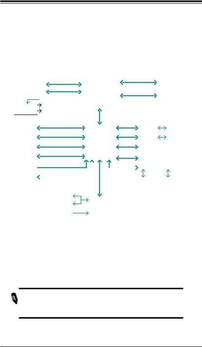
BLOCK DIAGRAM RoHS 6/6
P5-8
|
|
|
|
|
|
|
|
|
|
|
|
|
|
|
|
|
|
|
|
|
|
DDR3 (CHA) |
P9 |
|
|||||||||
P19 |
|
PCIe x8 SLOT |
PCIe2.0_x8 |
|
Xeon 3400 Series |
|
DIMM1(Far) |
|
|||||||||||||||||||||||||
|
|
|
|
|
|
|
|
DIMM2 |
|
||||||||||||||||||||||||
|
|
|
|
5.0Gb |
|
|
(Lynnfield) |
1333/1066MHz |
|
4 UDIMM |
|||||||||||||||||||||||
|
|
|
|
|
|
|
|
|
|
|
|
|
|
|
|||||||||||||||||||
P19 |
PCIe x8 SLOT |
PCIe2.0_x8 |
|
|
|
|
|
|
|
DDR3 (CHB) |
P10 |
4 RDIMM |
|||||||||||||||||||||
|
|
|
|
|
|
|
VID[0-7] |
|
|
5.0Gb |
|
|
Clarkdale |
|
DIMM1(Far) |
(4 Quad rank |
|||||||||||||||||
|
|
|
|
|
|
|
|
|
|
|
|
|
|
|
|
|
|
1333/1066MHz |
|
DIMM2 |
RDIMM run on |
||||||||||||
|
|
|
|
P28-29 |
|
|
|
|
|
|
|
|
|
|
|
|
|
|
|
|
|
|
|
|
|
|
800MHz) |
||||||
|
|
|
|
|
VRM 11.1 |
|
|
|
|
|
|
|
|
|
|
|
|
|
|
|
|
|
|
|
|
|
|
|
|
|
|||
|
|
|
|
|
MISC |
VRs |
|
|
|
|
|
|
|
|
|
DMIx4 2.5Gb |
|
|
|
|
|
|
|
|
|
|
|
|
|||||
|
|
|
|
P26-27 |
|
|
|
|
|
|
|
|
|
|
|
|
|
|
|
|
|
|
|
|
|
|
|
|
|
|
|
||
|
|
|
|
|
|
|
|
|
|
PCIe_x4 |
|
|
|
|
|
PCIe_x1 |
|
|
|
|
|
|
|
|
|
|
|||||||
|
|
P18PCIe x8 SLOT |
|
|
|
P11-14 |
|
GLAN1 |
|
|
|
|
|
|
|
||||||||||||||||||
|
|
|
|
|
|
RJ45 |
P16 |
||||||||||||||||||||||||||
|
|
|
|
|
|
|
|
|
|
|
|
2.5Gbps |
|
|
|
|
|
|
2.5Gbps |
82574L |
|
|
|
|
|
|
|
||||||
|
|
|
|
|
|
|
|
|
|
PCI 32 |
|
|
IBexPeak |
|
PCIe_x1 |
|
|
|
|
|
|
|
|
|
|
||||||||
|
|
P181 PCI 32 SLOT |
|
|
|
GLAN2 |
|
|
|
RJ45 |
P17 |
||||||||||||||||||||||
|
|
|
|
|
|
|
|
|
|
|
|
|
|
|
|
Intel 3400/3420 |
|
2.5Gbps |
82574L |
|
|
|
|
|
|
|
|||||||
|
|
|
|
|
|
|
|
|
|
|
|
SATA-II |
|
LPC |
|
|
|
|
P15(option) |
|
|||||||||||||
|
P124/6 |
|
SATA PORTS |
|
|
|
|
|
PCH |
|
TPM1.2 |
|
|
||||||||||||||||||||
|
|
|
|
|
|
|
|
|
|
|
|
300MB/s |
|
|
|
|
|
|
|
|
|
|
|
|
|
|
|
|
|
|
|||
|
|
|
|
|
|
|
|
|
|
|
|
USB2.0 |
|
|
|
|
|
|
|
|
P30-32 |
|
|
|
|
|
|
|
|||||
|
P21 |
|
|
|
|
|
|
|
|
|
|
|
|
|
|
|
|
|
|
|
PCI32 |
|
|
|
|
|
|
|
|
|
|
|
|
|
|
|
5/7 USB PORTS |
|
|
|
480Mbps |
|
|
|
|
|
|
|
HERMON WPCM450 |
|
|
|
|||||||||||||||
|
|
|
|
|
|
|
|
|
|
|
|
|
|
|
|
|
|
|
|
|
|
|
|
|
|
||||||||
|
|
|
|
|
|
|
|
|
|
|
|
|
|
|
|
|
|
|
|
|
|
|
|
|
|||||||||
|
|
|
|
|
P4 |
CK505 |
|
|
CLOCK |
|
|
|
|
|
|
LPC |
|
WINBOND |
|
|
|
|
|
|
|
||||||||
|
|
|
|
|
|
Rev1.0 |
|
|
|
|
|
|
|
|
|
|
|
|
|
|
|
|
|
|
|
|
|
|
|
|
|
||
|
|
|
|
|
|
|
|
|
SPI |
|
|
|
|
|
|
|
|
|
RMII |
|
|
|
|
|
|
|
|||||||
|
|
|
|
|
|
|
|
|
|
|
|
|
|
|
|
|
|
|
|
|
|
|
|
|
|
|
|
||||||
|
|
|
|
|
P15 |
FLASH |
|
|
|
|
|
|
|
|
|
|
|
|
|
|
|
|
|
|
|||||||||
|
|
|
|
|
|
SPI 16Mb |
|
|
|
|
|
|
|
|
|
|
|
|
|
|
|
RTL8201N |
|
|
VGA |
|
|||||||
|
|
|
|
|
|
|
|
|
|
|
|
|
|
|
|
|
|
LPC |
|
|
P33 |
|
|
P34 |
|
|
|||||||
|
|
|
|
|
|
|
|
|
|
|
|
|
|
|
|
|
|
|
|
PHY |
|
|
PORT |
|
|
||||||||
|
|
|
|
|
|
|
|
|
|
|
P23 |
|
|
|
|
|
|
|
|
|
|
|
|
|
|
|
|
|
|
|
|
|
|
|
|
|
|
|
|
|
|
|
|
|
COM1,2 |
|
|
P20 |
|
|
|
|
P33 |
|
|
|
|
|
|
|
|
|
|||||
|
|
|
|
|
|
|
|
|
|
|
P21 |
|
|
|
|
|
|
|
|
|
|
|
|
RJ45 |
|
|
|
|
|
|
|
|
|
|
|
|
|
|
|
|
|
|
|
|
P/S2 |
|
|
|
W83627DHG |
|
|
|
|
|
|
|
|
|
|
|
|
|
|
||||
|
|
|
|
|
|
|
|
|
|
|
|
|
|
|
|
|
LPC I/O |
|
|
|
|
|
|
|
|
|
|
|
|
|
|||
|
|
|
|
|
|
|
|
|
|
|
|
|
HEALTH |
|
|
|
|
|
|
|
|
|
|
|
|
|
|
|
|
|
|
||
|
|
|
|
|
|
|
|
|
|
|
|
|
INFO |
|
|
|
|
|
|
|
|
|
|
|
|
|
|
|
|
|
|
|
|
X8SIL/X8SIL-F/X8SIL-V System Block Diagram
 Note: This is a general block diagram and may not exactly represent
  the features on your motherboard. See the Motherboard Features
pages for the actual specifications of each motherboard.
1-9


 X8SIL/X8SIL-F/X8SIL-V User’s Manual
1-2 Chipset Overview
The X8SIL/X8SIL-F/X8SIL-V supports the Intel® Xeon® 3400 processor series.
Built upon the functionality and the capability of the single-chip Intel 3400 chipset, the X8SIL/X8SIL-F/X8SIL-V motherboard provides the performance and feature set required for single-processor-based systems with configuration options optimized for entry-level server platforms.
The high-speed Direct Media Interface (DMI) featured in the Intel 3400/3420 chipset enables the X8SIL/X8SIL-F/X8SIL-V motherboard to offer a high-speed Direct Media Interface (DMI) for chip-to-chip true isochronous communication with the processor. This feature allows the X8SIL/X8SIL-F/X8SIL-V to achieve up to 10
Gb/s of software-transparent data transfer on each direction, achieving better performance than comparable systems. The X8SIL/X8SIL-F/X8SIL-V also features a TCO timer (to enable the system to recover from a software/hardware lock), ECC Error Reporting, Function Disable and Intruder Detect.
Intel 3400/3420 Chipset Features
•Direct Media Interface (up 10 Gb/s transfer, Full Duplex)
•Intel® Matrix Storage Technology and Intel Rapid Storage Technology
•Dual NAND Interface
•Intel I/O Virtualization (VT-d) Support
•Intel Trusted Execution Technology Support
•PCI Express 2.0 Interface (up to 5.0 GT/s)
•SATA Controller (up to 3G/s)
•Advanced Host Controller Interface (AHCI)
1-10

Chapter 1: Introduction
1-3 PC Health Monitoring
This section describes the PC health monitoring features of the X8SIL/X8SIL-F/
X8SIL-V. These features are supported by an onboard System Hardware Monitor chip.
Recovery from AC Power Loss
BIOS provides a setting for you to determine how the system will respond when
AC power is lost and then restored to the system. You can choose for the system to remain powered off (in which case you must hit the power switch to turn it back on) or for it to automatically return to a power on state. See the Power Lost Control setting in the BIOS chapter of this manual to change this setting. The default setting is Last State.
Onboard Voltage Monitoring
The onboard voltage monitor will scan the following voltages continuously: CPU core, +3.3V, +5V, +/-12V, +3.3V Stdby, VBAT, Memory, VCORE for CPU. Once a voltage becomes unstable, it will give a warning or send an error message to the screen. Users can adjust the voltage thresholds to define the sensitivity of the voltage monitor by using SD III.
Fan Status Monitor with Software
PC health monitoring can check the RPM status of the cooling fans via Supero Doctor III.
CPU Overheat LED and Control
This feature is available when the user enables the CPU overheat warning feature in the BIOS. This allows the user to define an overheat temperature. When this temperature reaches this pre-defined overheat threshold, the CPU thermal trip feature will be activated and it will send a signal to the buzzer and, at the same time, the
CPU speed will be decreased.
1-4 Power Configuration Settings
This section describes the features of your motherboard that deal with power and power settings.
1-11


 X8SIL/X8SIL-F/X8SIL-V User’s Manual
Slow Blinking LED for Suspend-State Indicator
When the CPU goes into a suspend state, the chassis power LED will start blinking to indicate that the CPU is in the suspend mode. When the user presses any key, the CPU will wake-up and the LED indicator will automatically stop blinking and remain on.
BIOS Support for USB Keyboard
If the USB keyboard is the only keyboard in the system, it will function like a normal keyboard during system boot-up.
Main Switch Override Mechanism
When an ATX power supply is used, the power button can function as a system suspend button. When the user presses the power button, the system will enter a SoftOff state. The monitor will be suspended and the hard drive will spin down. Pressing the power button again to wake-up the whole system. During the SoftOff state, the ATX power supply provides power the system to keep the required circuitry "alive". In case the system malfunctions and you want to turn off the power, just press and hold the power button for 4 seconds. The power will turn off and no power will be provided to the motherboard.
1-5 Power Supply
As with all computer products, a stable power source is necessary for proper and reliable operation. It is even more important for processors that have high CPU clock rates of 1 GHz and faster.
The 


 X8SIL/X8SIL-F/X8SIL-V accommodates ATX12V standard power supplies. Although most power supplies generally meet the specifications required by the CPU, some are inadequate. A 2-Amp of current supply on a 5V Standby rail is strongly recommended.
It is strongly recommended that you use a high quality power supply that meets
ATX12V standard power supply Specification 1.1 or above. It is also required that the 12V 8-pin power connection (JPW2) be used for adequate power supply. In areas where noisy power transmission is present, you may choose to install a line filter to shield the computer from noise. It is recommended that you also install a power surge protector to help avoid problems caused by power surges.
1-12

Chapter 1: Introduction
1-6 Super I/O
The disk drive adapter functions of the Super I/O chip include a floppy disk drive controller that is compatible with industry standard 82077/765, a data separator, write pre-compensation circuitry, decode logic, data rate selection, a clock generator, drive interface control logic and interrupt and DMA logic. The wide range of functions integrated onto the Super I/O greatly reduces the number of components required for interfacing with floppy disk drives. The Super I/O supports two 360 K, 720 K, 1.2 M, 1.44 M or 2.88 M disk drives and data transfer rates of 250 Kb/s, 500 Kb/s or 1 Mb/s.
It also provides two high-speed, 16550-compatible serial communication ports (UARTs). Each UART includes a 16-byte send/receive FIFO, a programmable baud rate generator, complete modem control capability and a processor interrupt system. Both UARTs provide legacy speed with baud rate of up to 115.2 Kbps as well as an advanced speed with baud rates of 250 K, 500 K, or 1 Mb/s, which support higher speed modems.
The Super I/O provides functions that comply with ACPI (Advanced Configuration and Power Interface), which includes support of legacy and ACPI power management through a SMI or SCI function pin. It also features auto power management to reduce power consumption.
1-7 iSCSI Support
The X8SIL/X8SIL-F/X8SIL-V motherboard supports the iSCSI Internet Protocol. iSCSI is an IP networking standard used to link and manage data storage, and transfer data across the internet and private intranets through long distance. iSCSI can be used to transmit data over local area networks (LANs), wide area networks (WANs), or the Internet. It can enable location-independent data storage and retrieval.
iSCSI allow clients to issue SCSI commands to remote SCSI storage devices and allow data centers to consolidate remote storage devices into storage arrays, giving an illusion of locally-attached disks to host servers. Unlike fiber-optic networks that require special cabling, iSCSI can run over long distance using existing networks.
For the X8SIL/X8SIL-F/X8SIL-V motherboard, iSCSI is supported on LAN 1. This can be enabled through the BIOS: Advanced => PCI/PnP Configuration => Onboard
LAN1 Option ROM Select. Please see Chapter 4 for details.
1-13


 X8SIL/X8SIL-F/X8SIL-V User’s Manual
1-8 Overview of the Nuvoton BMC Controller
The NuvotonSM WPCM150 is a combined Baseboard Management Controller and
2D/VGA-compatible Graphics Core with PCI interface, Virtual Media and Keyboard, and a Keyboard/Video/Mouse Redirection (KVMR) module.
The WPCM150 interfaces with the host system via a PCI interface to communicate with the Graphics core. It supports USB 2.0 and 1.1 for remote keyboard/mouse/ virtual media emulation. It also provides an LPC interface to control Super I/O functions and connects to the network via an external Ethernet PHY module or shared NCSI connections.
The Nuvoton BMC communicates with onboard components via six SMBus interfaces, fan control, Platform Environment Control Interface (PECI) buses, and
General Purpose I/O (T-SGPIO) ports.
There are two different versions of the Nuvoton BMC chip that are used in this product series. The Nuvoton WPCM150 (Manufacturer P/N WPCM150GA0BX5) which includes all of the features above, is the chip installed in the X8SIL and X8SIL-V motherboard models. Another version, the Nuvoton WPCM450 (Manufacturer P/N WPCM450RA0BX) also has all the features as described above plus IPMI 2.0 support. This particular chip is installed in the X8SIL-F motherboard.
Note: For more information on IPMI configuration, please refer to the
Embedded IPMI User's Guide posted on our website @ http://www.supermicro.com/support/manuals/. For detailed information regarding Nuvoton BMC products, go to Nuvoton's website at http://www.nuvoton.com and enter the manufacturer part numbers mentioned above in the website's
Product Search.
1-14

Chapter 2: Installation
Chapter 2
Installation
2-1 Static-Sensitive Devices
Electrostatic-Discharge (ESD) can damage electronic components. To prevent damage to your system board, it is important to handle it very carefully. The following measures are generally sufficient to protect your equipment from ESD.
Precautions
•Use a grounded wrist strap designed to prevent static discharge.
•Touch a grounded metal object before removing the board from the antistatic bag.
•Handle the board by its edges only; do not touch its components, peripheral chips, memory modules or gold contacts.
•When handling chips or modules, avoid touching their pins.
•Put the motherboard and peripherals back into their antistatic bags when not in use.
•For grounding purposes, make sure your computer chassis provides excellent conductivity between the power supply, the case, the mounting fasteners and the motherboard.
•Use only the correct type of onboard CMOS battery. Do not install the onboard upside down battery to avoid possible explosion.
Unpacking
The motherboard is shipped in antistatic packaging to avoid static damage. When unpacking the board, make sure the person handling it is static protected.
2-1


 X8SIL/X8SIL-F/X8SIL-V User's Manual
|
2-2 |
Processor and Heatsink Installation |
|
! |
Warning: When handling the processor package, avoid placing direct |
||
pressure on the label area of the fan. |
|||
|
Notes: |
|
|
|
Always connect the power cord last and always remove it before adding, |
||
|
removing or changing any hardware components. Make sure that you in- |
||
|
stall the processor into the CPU socket before you install the CPU heatsink. |
||
|
If you buy a CPU separately, make sure that you use an Intel-certified |
||
|
multi-directional heatsink only. |
||
|
Make sure to install the serverboard into the chassis before you install |
||
|
the CPU heatsinks. |
||
|
When receiving a serverboard without a processor pre-installed, make |
||
|
sure that the plastic CPU socket cap is in place and none of the socket |
||
|
pins are bent; otherwise, contact your retailer immediately. |
||
|
Refer to the Supermicro web site for updates on CPU support. |
||
|
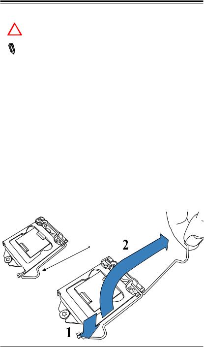
Installing the LGA1156 Processor |
||
|
Press the load lever to release the load plate, which covers the CPU socket, |
||
1 |
|||
from its locking position. |
|||
Load
2-2
Chapter 2: Installation
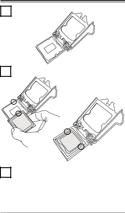
2
3
4
Gently lift the load lever to open the load plate. Remove the plastic cap.
Use your thumb and your index finger to hold the CPU at the top center edge and the bottom center edge of the CPU.
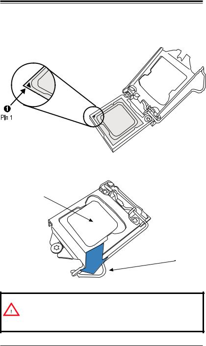
Align the CPU key that is the semi-circle cutouts against the socket keys. Once aligned, carefully lower the CPU straight down to the socket. (Do not drop the CPU on the socket. Do not move the CPU horizontally or vertically.
2-3


 X8SIL/X8SIL-F/X8SIL-V User's Manual
Do not rub the CPU against the surface or against any pins of the socket to avoid damage to the CPU or the socket.)
With the CPU inside the socket, inspect the four corners of the CPU to make sure that the CPU is properly installed.
|
|
|
|
|
|
Use your thumb to gently push the load lever down to the lever lock. |
|
5 |
|||
CPU properly installed 
Load lever locked into place
Warning: The CPU will only seat inside the socket in one direction. Make sure it is properly inserted before closing the load plate. If it doesn't close properly, do not force it as it may damage your CPU. Instead, open the load plate again and double-check that the CPU is aligned properly.
2-4
Chapter 2: Installation
1
2
Installing a Passive CPU Heatsink
Do not apply any thermal grease to the heatsink or the CPU die -- the required amount has already been applied.
Place the heatsink on top of the CPU so that the four mounting holes are aligned with those on the Motherboard's and the Heatsink Bracket underneath.
3 |
Screw in two diagonal screws (i.e., the #1 and the #2 screws) until just snug |
|
|
|
(do not over-tighten the screws to avoid possible damage to the CPU.) |
4 |
Finish the installation by fully tightening all four screws. |
|
Recommended Supermicro heatsink: |
|
SNK-P0046P heatsink with BKT-0028L |
|
bottom bracket |
Screw#1
Screw#2
Motherboard 
Mounting
Holes
Heatsink Bracket 
2-5


 X8SIL/X8SIL-F/X8SIL-V User's Manual
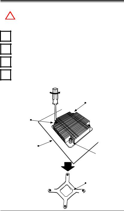
Removing the Heatsink
Warning: We do not recommend that the CPU or the heatsink be removed.
!However, if you do need to uninstall the heatsink, please follow the instructions below to uninstall the heatsink to prevent damage done to the CPU or the CPU socket.
1Unscrew the heatsink screws from the motherboard in the sequence as shown in the illustration below.
2Gently wriggle the heatsink to loosen it from the CPU. (Do not use excessive force when wriggling the heatsink!!)
3Once the CPU is loosened, remove the heatsink from the CPU socket.
4Clean the surface of the CPU and the heatsink, removing the used thermal grease. Reapply the proper amount of thermal grease on the surface before re-installing the CPU and the heatsink.
Loosen screws in se- |
|
quence as shown. |
Screw#4 |
Screw#1

 Screw#2
Motherboard
 Screw#3
Remove the Heatsink Bracket from underneath the motherboard.
2-6
Chapter 2: Installation
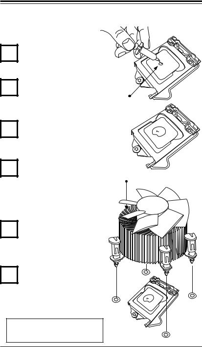
Installing an Active Fan CPU Heatsink
1
2
3
Locate the CPU Fan power connector on the motherboard. (Refer to the layout on the right for the CPU Fan location.)
Position the heatsink so that the |
|
|
heatsink fan wires are closest |
|
|
to the CPU fan power connector |
Thermal Grease |
|
and are not interfered with other |
||
|
||
components. |
|
Inspect the CPU Fan wires to make sure that the wires are routed through the bottom of the heatsink.
4
5
6
Remove the thin layer of the pro- |
|
tective film from the copper core |
Heatsink Fins |
of the heatsink. |
|
(Warning: CPU may overheat if |
|
the protective film is not removed |
|
from the heatsink.) |
|
Apply the proper amount of |
|
thermal grease on the CPU. |
|
(Note: if your heatsink came with |
|
a thermal pad, please ignore this |
|
step.) |
|
If necessary, rearrange the wires |
|
to make sure that the wires are |
|
not pinched between the heatsink |
|
and the CPU. Also make sure to |
|
keep clearance between the fan |
|
wires and the fins of the heatsink. |
|
Recommended Supermicro heatsink: SNK-P0046A4 active heatsink
2-7


 X8SIL/X8SIL-F/X8SIL-V User's Manual
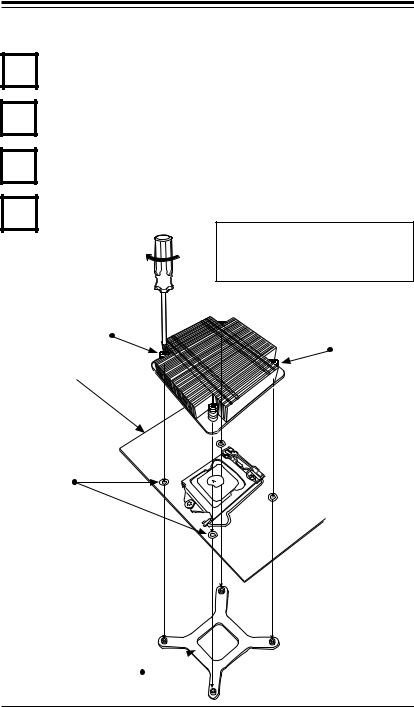
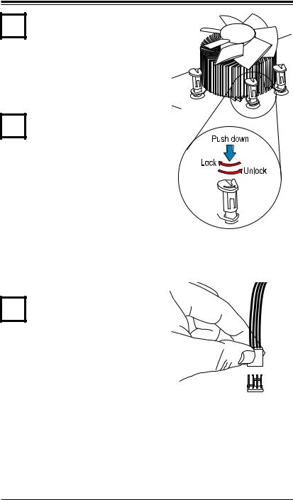
7
8
Align the four heatsink fasteners with the mounting holes on the motherboard. Gently push the pairs of diagonal fasteners (#1 & #2, and #3 & #4) into the mounting holes until you hear a click. (Note: Make sure to orient each fastener so that the narrow end of the groove is pointing outward.)
Repeat Step 7 to insert all four heatsink fasteners into the mounting holes.
9 |
Once all four fasteners are se- |
curely inserted into the mounting |
|
holes and the heatsink is proper- |
ly installed on the motherboard, connect the heatsink fan wires to the CPU Fan connector.
2-8
Chapter 2: Installation
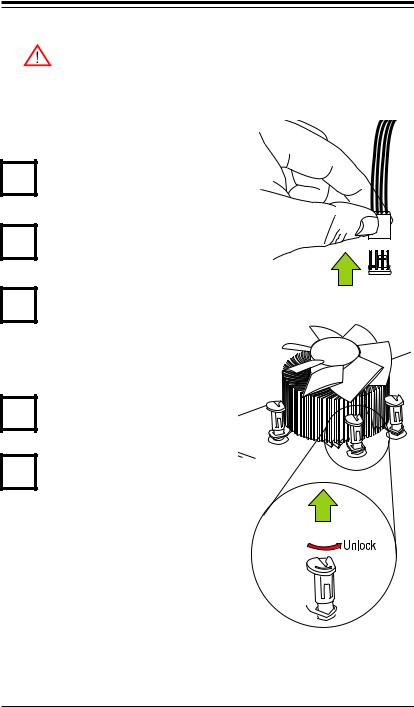
Removing the Heatsink
Warning: We do not recommend that the CPU or the heatsink be removed. However, if you do need to remove the heatsink, please follow the instructions below to uninstall the heatsink and prevent damage to the CPU or other components.
Active Heatsink Removal
1 |
Unplug the power cord from the power |
|
|
|
|
|
supply. |
|
2 |
Disconnect the heatsink fan wires from |
|
the CPU fan header. |
|
|
3 |
Use your finger tips to gently press on |
Remove |
the fastener cap and turn it counter- |
|
|
clockwise to make a 1/4 (900) turn, |
|
and then pull the fastener upward to loosen it.
4
5
Repeat Step 3 to loosen all fasteners from the mounting holes.
With all fasteners loosened, remove the heatsink from the CPU.

 Pull Up
2-9
 Loading...