


SUPER ®
H8DGi
H8DGi-F
H8DG6
H8DG6-F
USER’S MANUAL
Revision 1.1c
The information in this User’s Manual has been carefully reviewed and is believed to be accurate. The vendor assumes no responsibility for any inaccuracies that may be contained in this document, makes no commitment to update or to keep current the information in this manual, or to notify any person or organization of the updates. Please Note: For the most up-to-date version of this manual, please see our web site at www.supermicro.com.
Super Micro Computer, Inc. ("Supermicro") reserves the right to make changes to the product described in this manual at any time and without notice. This product, including software and documentation, is the property of Supermicro and/or its licensors, and is supplied only under a license. Any use or reproduction of this product is not allowed, except as expressly permitted by the terms of said license.
IN NO EVENT WILL SUPERMICRO BE LIABLE FOR DIRECT, INDIRECT, SPECIAL, INCIDENTAL, SPECULATIVE OR CONSEQUENTIAL DAMAGES ARISING FROM THE USE OR INABILITY TO USE THIS PRODUCT OR DOCUMENTATION, EVEN IF ADVISED OF THE POSSIBILITY OF SUCH DAMAGES. IN PARTICULAR, SUPERMICRO SHALL NOT HAVE LIABILITY FOR ANY HARDWARE, SOFTWARE, OR DATA STORED OR USED WITH THE PRODUCT, INCLUDING THE COSTS OF REPAIRING, REPLACING, INTEGRATING, INSTALLING OR RECOVERING SUCH HARDWARE, SOFTWARE, OR DATA.
Any disputes arising between manufacturer and customer shall be governed by the laws of Santa Clara County in the State of California, USA. The State of California, County of Santa Clara shall be the exclusive venue for the resolution of any such disputes. Super Micro's total liability for all claims will not exceed the price paid for the hardware product.
FCC Statement: This equipment has been tested and found to comply with the limits for a Class A digital device pursuant to Part 15 of the FCC Rules. These limits are designed to provide reasonable protection against harmful interference when the equipment is operated in a commercial environment. This equipment generates, uses, and can radiate radio frequency energy and, if not installed and used in accordance with the manufacturer’s instruction manual, may cause harmful interference with radio communications. Operation of this equipment in a residential area is likely to cause harmful interference, in which case you will be required to correct the interference at your own expense.
California Best Management Practices Regulations for Perchlorate Materials: This Perchlorate warning applies only to products containing CR (Manganese Dioxide) Lithium coin cells. “Perchlorate Material-special handling may apply. See www.dtsc.ca.gov/hazardouswaste/perchlorate”
WARNING: Handling of lead solder materials used in this product may expose you to lead, a chemical known to the State of California to cause birth defects and other reproductive harm.
Manual Revision 1.1c
Release Date: August 13, 2012
Unless you request and receive written permission from SUPER MICRO COMPUTER, you may not copy any part of this document.
Information in this document is subject to change without notice. Other products and companies referred to herein are trademarks or registered trademarks of their respective companies or mark holders.
Copyright © 2012 by SUPER MICRO COMPUTER INC.
All rights reserved.
Printed in the United States of America

Preface
Preface
About This Manual
This manual is written for system integrators, PC technicians and knowledgeable PC users. It provides information for the installation and use of the H8DG6/i(-F) serverboard.
The H8DG6/i(-F) serverboard is based on the AMD® Dual SR5690 and one SP5100 chipset and supports two AMD Socket G34 type processor with up to 128 GB of ECC/Non-ECC UDIMM or 512 GB of ECC RDIMM. This board series includes the following serverboards and characteristics:
|
Embeded IPMI |
Onboard SAS2 |
H8DG6 |
|
Yes |
H8DGi |
|
|
H8DG6-F |
Yes |
Yes |
H8DGi-F |
Yes |
|
|
|
|
Please refer to the motherboard specifications pages on our web site for updates on supported processors (http://www.supermicro.com/aplus/). This product is intended to be professionally installed.
Manual Organization
Chapter 1 includes a checklist of what should be included in your motherboard box, describes the features, specifications and performance of the motherboard and provides detailed information about the chipset.
Chapter 2 begins with instructions on handling static-sensitive devices. Read this chapter when installing the processor(s) and memory modules and when installing the motherboard in a chassis. Also refer to this chapter to connect the hard disk drives, the various ports, and the power and reset buttons and the system LEDs.
If you encounter any problems, see Chapter 3, which describes troubleshooting procedures for the video, the memory and the setup configuration stored in CMOS. For quick reference, a general FAQ (Frequently Asked Questions) section is provided. Instructions are also included for contacting technical support. In addition, you can visit our web site for more detailed information.
Chapter 4 includes an introduction to BIOS and provides detailed information on running the CMOS Setup utility.
Appendix A provides BIOS Error Beep Code Messages.
Appendix B lists BIOS POST Checkpoint Codes.
iii

|
|
Table of Contents |
|
|
|
|
Table of Contents |
|
Chapter 1 Introduction |
|
|
1-1 |
Overview ......................................................................................................... |
1-1 |
|
Checklist.......................................................................................................... |
1-1 |
1-2 |
Contacting Supermicro.................................................................................... |
1-2 |
|
H8DG6/i(-F) Quick Reference......................................................................... |
1-5 |
1-3 |
Chipset Overview .......................................................................................... |
1-10 |
|
AMD SR5690/SP5100 Chipset ..................................................................... |
1-10 |
|
HyperTransport Technology .......................................................................... |
1-10 |
1-4 |
PC Health Monitoring.................................................................................... |
1-10 |
1-5 |
Power Configuration Settings......................................................................... |
1-11 |
1-6 |
Power Supply ................................................................................................ |
1-12 |
1-7 |
Super I/O....................................................................................................... |
1-13 |
Chapter 2 Installation |
|
|
2-1 |
Static-Sensitive Devices.................................................................................. |
2-1 |
|
Precautions ..................................................................................................... |
2-1 |
|
Unpacking ....................................................................................................... |
2-1 |
2-2 Processor and Heatsink Installation................................................................ |
2-2 |
|
2-3 Mounting the Motherboard into a Chassis...................................................... |
2-4 |
|
2-4 |
Installing Memory ............................................................................................ |
2-4 |
|
DIMM Module Population Configuration .................................................... |
2-6 |
2-5 |
PCI Expansion Cards...................................................................................... |
2-7 |
2-6 I/O Port and Control Panel Connections ........................................................ |
2-8 |
|
|
Front Control Panel......................................................................................... |
2-8 |
2-7 |
Connector Definitions ..................................................................................... |
2-9 |
|
Power Connectors ..................................................................................... |
2-9 |
|
Power LED Connector ............................................................................... |
2-9 |
|
HDD/FP UID Switch ................................................................................... |
2-9 |
|
Overheat (OH)/Fan Fail/PWR Fail/UID LED ............................................ |
2-10 |
|
Power Fail LED ........................................................................................ |
2-10 |
|
Reset Connector ...................................................................................... |
2-10 |
|
Power Button............................................................................................ |
2-10 |
|
Serial Ports................................................................................................ |
2-11 |
|
Fan Headers.............................................................................................. |
2-11 |
|
Power LED/Speaker.................................................................................. |
2-11 |
|
Chassis Intrusion ...................................................................................... |
2-11 |
|
Overheat LED........................................................................................... |
2-12 |
v

|
|
Table of Contents |
|
|
|
|
Power I2C................................................................................................. |
2-12 |
|
Trusted Platform Module Header ............................................................. |
2-12 |
|
JSMB1 ...................................................................................................... |
2-12 |
|
Wake-On-LAN .......................................................................................... |
2-13 |
|
LAN1/2 (Ethernet Ports)........................................................................... |
2-13 |
|
ATX PS/2 Keyboard and PS/2 Mouse Ports............................................ |
2-13 |
|
DOM Power Connector ............................................................................ |
2-13 |
|
SGPIO ...................................................................................................... |
2-14 |
|
Unit Identifier Button................................................................................. |
2-14 |
|
Universal Serial Bus Ports ....................................................................... |
2-14 |
|
USB Headers ........................................................................................... |
2-14 |
|
Video Connector....................................................................................... |
2-15 |
|
JIBTN1 Header......................................................................................... |
2-15 |
2-8 |
Jumper Settings ............................................................................................ |
2-16 |
|
Explanation of Jumpers ................................................................................ |
2-16 |
|
CMOS Clear ............................................................................................. |
2-16 |
|
LAN Enable/Disable ................................................................................ |
2-17 |
|
SAS Enable/Disable ................................................................................. |
2-17 |
|
VGA Enable/Disable................................................................................. |
2-17 |
|
I2C to PCI-Express Slot ........................................................................... |
2-17 |
|
BMC Jumper ............................................................................................ |
2-17 |
|
Watch Dog Enable/Disable ...................................................................... |
2-18 |
|
USB Wake-Up ......................................................................................... |
2-18 |
2-9 |
Onboard Indicators........................................................................................ |
2-18 |
|
LAN1/LAN2 LEDs..................................................................................... |
2-18 |
|
Dedicated IPMI LAN LEDs ..................................................................... |
2-18 |
|
BMC Heartbeat LED ................................................................................ |
2-19 |
|
Power LED ............................................................................................... |
2-19 |
|
SAS2008 Heartbeat LED ......................................................................... |
2-19 |
|
UID LED (LE1) ........................................................................................ |
2-19 |
2-10 SAS and SATA Drive Connections ............................................................... |
2-20 |
|
|
SATA Ports ............................................................................................... |
2-20 |
|
SAS Ports................................................................................................. |
2-20 |
vi

H8DG6/i(-F) SERVERBOARD USER'S MANUAL
2-11 |
Enabling SATA RAID..................................................................................... |
2-21 |
|
Serial ATA (SATA).......................................................................................... |
2-21 |
|
Installing the OS/SATA Driver ....................................................................... |
2-21 |
|
Building a Driver Diskette......................................................................... |
2-21 |
|
Enabling SATA RAID in the BIOS................................................................. |
2-22 |
|
Using the Adaptec RAID Utility ..................................................................... |
2-23 |
|
Installing the RAID Driver During OS Installation ......................................... |
2-23 |
2-12 |
Installing Drivers............................................................................................ |
2-24 |
|
Supero Doctor III........................................................................................... |
2-25 |
2-13 |
Serverboard Battery ...................................................................................... |
2-27 |
Chapter 3 Troubleshooting
3-1 |
Troubleshooting Procedures ........................................................................... |
3-1 |
|
Before Power On ............................................................................................ |
3-1 |
|
No Power ........................................................................................................ |
3-1 |
|
No Video ......................................................................................................... |
3-1 |
|
Memory Errors ............................................................................................... |
3-2 |
|
Losing the System’s Setup Configuration....................................................... |
3-2 |
3-2 |
Technical Support Procedures ........................................................................ |
3-2 |
3-3 |
Frequently Asked Questions ........................................................................... |
3-3 |
3-4 |
Returning Merchandise for Service................................................................. |
3-4 |
Chapter 4 BIOS
4-1 |
Introduction...................................................................................................... |
4-1 |
4-2 |
Main Menu ...................................................................................................... |
4-2 |
4-3 |
Advanced Settings Menu ................................................................................ |
4-2 |
4-3 |
Security Menu ............................................................................................... |
4-15 |
4-4 |
Boot Menu..................................................................................................... |
4-16 |
4-5 |
Exit Menu ...................................................................................................... |
4-17 |
Appendix A BIOS Error Beep Codes |
|
|
Appendix B BIOS POST Checkpoint Codes |
|
|
B-1 |
Uncompressed Initialization Codes................................................................. |
B-1 |
B-2 |
Bootblock Recovery Codes............................................................................. |
B-2 |
B-3 |
Uncompressed Initialization Codes................................................................. |
B-3 |
vii

Chapter 1: Introduction
Chapter 1
Introduction
1-1 Overview
Checklist
Congratulations on purchasing your computer motherboard from an acknowledged leader in the industry. Supermicro boards are designed with the utmost attention to detail to provide you with the highest standards in quality and performance.
Please check that the following items have all been included with your motherboard. If anything listed here is damaged or missing, contact your retailer.
•One (1) H8DG6/i(-F) serverboard
•One (1) I/O shield (MCP-260-00027-0N)
•One (1) 9-pin serial port cable (CBL-0010L)
•One (1) 15.7-inch USB 2.0 2-Port with Key cable (CBL-0083L)
•Two (2) 50-cm I-Pass to four SATA PBF cables (CBL-0097L-02) (for H8DG6 and H8DG6-F only)
•Four (4) 2ft. Amphenol, SATA cable (CBL-0044L) (Six for H8DGi or H8DGi-F)
Note: For your system to work properley, please follow the links below to download all necessary drivers/utilities and the user’s manual for your server.
•SMCI product manuals: http://www.supermicro.com/support/manuals/
•Product drivers and utilities: ftp://ftp.supermicro.com
•If you have any questions, please contact our support team at support@ supermicro.com
1-1

H8DG6/i(-F) SERVERBOARD USER'S MANUAL
1-2 Contacting Supermicro
Headquarters
Address: |
Super Micro Computer, Inc. |
|
980 Rock Ave. |
|
San Jose, CA 95131 U.S.A. |
Tel: |
+1 (408) 503-8000 |
Fax: |
+1 (408) 503-8008 |
Email: |
marketing@supermicro.com (General Information) |
|
support@supermicro.com (Technical Support) |
Web Site: |
www.supermicro.com |
Europe
Address: |
Super Micro Computer B.V. |
|
Het Sterrenbeeld 28, 5215 ML |
|
's-Hertogenbosch, The Netherlands |
Tel: |
+31 (0) 73-6400390 |
Fax: |
+31 (0) 73-6416525 |
Email: |
sales@supermicro.nl (General Information) |
|
support@supermicro.nl (Technical Support) |
|
rma@supermicro.nl (Customer Support) |
Asia-Pacific
Address: |
Super Micro Computer, Inc. |
|
4F, No. 232-1, Liancheng Rd. |
|
Chung-Ho Dist., New Taipei City 235 |
|
Taiwan, R.O.C. |
Tel: |
+886-(2) 8226-3990 |
Fax: |
+886-(2) 8226-3991 |
Web Site: |
www.supermicro.com.tw |
Technical Support: |
|
Email: |
support@supermicro.com.tw |
Tel: |
+886-(2) 8226-5990 |
1-2

Chapter 1: Introduction
Figure 1-1. H8DG6/i(-F) Image
1-3

H8DG6/i(-F) SERVERBOARD USER'S MANUAL
Figure 1-2. H8DG6/i(-F) Motherboard Layout
(not drawn to scale)
LE1 |
JPL1 |
VGA |
UID |
|
LAN2
 LAN1
LAN1

DP1 |
|
BMC |
|
INTEL |
|
|
|
FAN5 |
|
Windbond |
|
82576 |
|
|
|
||
JWOL1 |
|
|
|
|
|
|
|
|
JPB1 |
|
|
|
|
|
|
|
FAN7/CPU1 |
|
JPG1 |
|
|
JSMB1 |
|
|
|
|
SGPIO2-TSGPIO1-T USB4/5 USB2/3 |
X8)(IN X4 0.2 E-PCI SLOT1 |
|
|
X8)(IN X4 0.2 E-PCI SLOT5 |
|
|
||
X160.2E-PCI SLOT2 |
X8 0.2 E-PCI SLOT3 |
X160.2E-PCI SLOT4 |
JI2C1 JI2C2 |
X160.2E-PCI SLOT6 |
||||
JWD1 |
|
|
|
|
|
|
|
|
|
|
|
|
|
|
|
|
CPU1 |
BATTERY |
|
|
|
|
|
|
|
|
JBT1
JOH1
AMD
SP5100
SATA0 |
|
SATA1 |
|
AMD |
|
|
|
|
|
|
|
|
|
|
SR5690 |
|
|
|
|
|
|
|
|
||
|
|
|
|
|
|
|
|
|
|
|
|
|
SATA2 |
|
SATA3 |
JPS1 |
|
|
|
|
|
|
|
|
|
|
|
|
|
|
|
|
|
|
|
|
|
|
SATA4 |
|
COM2 |
|
JL1 |
|
|
|
|
|
|
|
|
1 |
|
|
|
|
|
|
|
|
|
|
||
JWF1 |
|
|
|
|
|
|
|
|
|
|
||
SATA5 |
|
|
|
-P2 |
-P2 |
-P2 |
-P2 |
-P2 |
-P2 |
-P2 |
-P2 |
|
LEDS1 |
LSI |
AMD |
DIMM1A |
DIMM1B |
DIMM2A |
DIMM2B |
DIMM3A |
DIMM3B |
DIMM4A |
DIMM4B |
||
|
|
|
2008 |
SR5690 |
|
|
|
|
|
|
|
|
|
|
|
|
|
|
|
|
|
|
|
|
|
USB6 |
|
|
SAS2 |
|
|
|
|
|
|
|
|
|
|
JTPM1 |
|
|
|
|
|
|
|
|
|
|
|
USB7 |
|
|
|
|
|
|
|
|
|
|
|
|
SAS 4~7 |
SAS 0~3 |
|
|
|
|
JIBTN1 |
|
JD1 |
DP3 |
|
|
|
FAN4 |
JF1 |
FAN3 |
FAN2 |
FAN1 |
COM1
FAN6 |
DIMM4B-P1 |
DIMM4A-P1 |
DIMM3B-P1 |
DIMM3A-P1 |
CPU2
JPI2C1
USB0/1 LAN IPMI |
KB/MOUSE |
DIMM2B-P1 |
DIMM2A-P1 |
DIMM1B-P1 |
DIMM1A-P1 |
JPW1
JPW3 |
JPW2 |
FAN8/CPU2
Notes:
Jumpers not indicated are for test purposes only.
Not all ports, jumpers or LED Indicators are available on all serverboards.
1-4
|
|
Chapter 1: Introduction |
|
|
|
||
|
H8DG6/i(-F) Quick Reference |
||
Jumper |
Description |
Default Setting |
|
JBT1 |
CMOS Clear |
(See Section 2-7) |
|
JI2C1/JI2C2 |
I2C to PCI-E Slot Enable/Disable |
Both Open (Disabled) |
|
JPB1 |
BMC Enable/Disable |
Pins 1-2 (Enabled) |
|
JPG1 |
VGA Enable/Disable |
Pins 1-2 |
(Enabled) |
JPL1 |
LAN 1 Enable/Disable |
Pins 1-2 |
(Enabled) |
JPS1 |
SAS Controller Enable/Disable |
Pins 1-2 |
(Enabled) |
JWD1 |
Watch Dog |
Pins 1-2 |
(Reset) |
LED |
Description |
|
|
LAN Ports |
LEDs for the LAN Ethernet ports |
|
|
Dedicated IPMI LAN |
LEDs for the dedicated IPMI LAN Ethernet port (H8DGi/6-F only) |
||
DP1 |
LED for BMC Heartbeat |
|
|
DP3 |
LED for Serverboard Power-On |
|
|
LE1 |
LED for UID Button |
|
|
LEDS1 |
SAS2008 Heartbeat LED |
|
|
1-5

H8DG6/i(-F) SERVERBOARD USER'S MANUAL
Connector |
Description |
COM1/COM2 |
COM1 Serial Port/Header |
FAN 1-8 |
Chassis/CPU Fan Headers |
IPMI LAN |
Dedicated IPMI LAN Port (H8DGi/6-F only) |
JD1 |
Speaker Header |
JF1 |
Front Panel Connector |
JIBTN1 |
RAIDKey for RAID 5 SAS support (optional for H8DG6(-F) only) |
JL1 |
Chassis Intruder Header |
JOH1 |
Overheat Warning Header |
JPI2C1 |
Power I2C Header |
JPW1 |
24-pin Main ATX Power Connector |
JPW2/3 |
+12V 8-pin CPU Power Connectors |
JTPM1 |
Trusted Platform Module Header |
JSMB1 |
System Management Bus Header (SMBus) |
JWF1 |
SATA DOM (Disk_On_Module) PWR |
JWOL1 |
Wake-On-LAN Header |
LAN1/2 |
Gigabit Ethernet (RJ45) Ports |
PS2 Mouse/Keyboard |
PS2 Mouse/Keyboard connectors |
SAS0~3, SAS4~7 |
SAS Ports (H8DG6(-F) only) |
SATA0 ~ SATA5 |
SATA Ports |
T-SGPIO-1/T-SGPIO-2 |
Serial General Purpose Input/Output Header for SATA |
USB0/1, USB2/3, USB4/5, USB6/7 |
Universal Serial Bus (USB) Ports, Headers and Type-A Port |
VGA |
VGA Connector |
1-6

Chapter 1: Introduction
Motherboard Features
CPU
• Dual AMD Opteron 6000 series (AMD Socket G34 type) processor
Note: Refer to our web site for details on supported processors.
Memory
•Sixteen (16) four channel DIMM slots support up to 128 GB of ECC/Non-ECC UDIMM or 512 GB of ECC RDIMM, with DDR3-1600/1333/1066 Mhz speed SDRAM in 1 GB, 2 GB, 4 GB, 8 GB, 16 GB or 32 GB sizes of 1.5V or 1.35V voltages.
Note: Refer to Section 2-4 before installing memory and our web site for recommended DIMMs.
Chipset
• Dual AMD SR5690 chipsets and one SP5100 Southbridge chipset
Expansion Slots
•Three (3) PCI-Express x16 Gen. 2
•One (1) PCI-Express x8 Gen. 2
•Two (2) PCI-Express x4 (in x8 slot) Gen. 2
BIOS
•16 Mb AMIBIOS® SPI Flash ROM
•DMI 2.3, PCI 2.2, ACPI 1.0 (ACPI 2.0 is BIOS supported), SMBIOS 2.3, Real Time Clock Wakeup, Plug and Play (PnP), BIOS resume hot keys, Hardware BIOS Virus Protection
PC Health Monitoring
•Onboard voltage monitors
•Fan status monitor with firmware/software on/off and speed control
•Watch Dog
•Environmental temperature monitoring via BIOS
•Power-up mode control for recovery from AC power loss
•System resource alert (via included utility program)
•Auto-switching voltage regulator for the CPU core
1-7

H8DG6/i(-F) SERVERBOARD USER'S MANUAL
•CPU thermal trip support
•I2C temperature sensing logic
•Chipkill Support
ACPI Features
•Microsoft OnNow
•Slow blinking LED for suspend state indicator
•BIOS support for USB keyboard
•Wake-On-LAN (WOL)
Onboard I/O
•Six (6) SATA ports supported by an on-chip SATA controller (RAID 0, 1, 10 supported)
•Eight (8) SAS ports supported by an LSI 2008 SAS2 controller (RAID 0, 1, 10 supported; Raid 5 Optional) (H8DG6(-F) only)
•Eight (8) USB (Universal Serial Bus 2.0) ports (2x rear, 2x headers (USB 2/3 and USB 4/5), 2x type A)
•Two (2) LAN ports supported by one onboard Intel® 82576 Ethernet controllers for 10/100/1000Base-T
•One (1) dedicated IPMI LAN port (H8DG6/i-F only)
•One (1) VGA port supported by an onboard Matrox® G200 graphics controller (with 16 MB DDR2 memory)
•Two COM Ports (one external serial port, one Fast UART 16550 port)
Other
•Onboard power LED
•Chassis intrusion detection
CD Utilities
•BIOS flash upgrade utility
•Super Doctor III
•IPMI 1.5 / 2.0
Dimensions
• Extended-ATX form: (LxW) 12" x 13" (305 x 330 mm)
1-8

Chapter 1: Introduction
Figure 1-3. AMD Dual SR5690 and one SP5100 Chipset: System Block Diagram
Note: This is a general block diagram and may not exactly represent the features on your motherboard. See the previous pages for the actual specifications of your motherboard.
DDR3 |
VRM |
1600/1333/1066 |
|
8x DIMM
SLOT#2
PCIE_(X16)
SLOT#1
PCIE_(X4)
SLOT#4
PCIE_(X16)
G34-SOCKET #2
HT16/16 Link2- .6GHz
AMD SR5690#2
VRM |
DDR3 |
HT Link |
1600/1333/1066 |
16 x16 bits 6.4GHz |
8x DIMM |
G34-SOCKET #1 |
LAN
Intel 82576
HT16/16 Link2- .6GHz
PCIE (x4)
AMD
SR5690#1
PCIE (X8) |
LSI |
|
|
|
SAS2 2008 |
PCIE (X4) |
SLOT#5 |
|
PCIE_(X4) |
PCIE (X8) |
SLOT#3 |
|
PCIE_(X8) |
PCIE (X16) |
SLOT#6 |
|
PCIE_(X16) |
VGA
Winbond
WPCM450
AMD SP5100
SATA
USB
 SATA PORT X6
 USB PORT X8
LPC BUS
H/W_MONITOR |
LPC SIO |
|
W83627DHG-P |
||
W83795 |
FWH
FAN |
KEYBOARD/ |
CONN. (8) |
MOUSE |
1-9

H8DG6/i(-F) SERVERBOARD USER'S MANUAL
1-3 Chipset Overview
The H8DG6/i(-F) serverboard is based on the AMD Dual SR5690 and one SP5100 chipset. This chipset functions as a Media and Communications Processor (MCP). Controllers for the system memory are integrated directly into AMD Opteron processors.
AMD SR5690/SP5100 Chipset
The AMD Dual SR5690 and one SP5100 are each a single-chip, high-performance HyperTransport peripheral controller. It includes a 42-lane PCI Express interface, an AMD Opteron 16-bit Hyper Transport interface link, a six-port Serial ATA interface and an eight-port USB 2.0 interface. This hub connects directly to the CPU.
HyperTransport Technology
HyperTransport technology is a high-speed, low latency point to point link that was designed to increase the communication speed by a factor of up to 48x between integrated circuits. This is done partly by reducing the number of buses in the chipset to reduce bottlenecks and by enabling a more efficient use of memory in multi-processor systems. The end result is a significant increase in bandwidth within the chipset.
1-4 PC Health Monitoring
This section describes the PC health monitoring features of the H8DG6/i(-F) serverboard. The serverboard has an onboard System Hardware Monitor chip that supports PC health monitoring.
Onboard Voltage Monitors
The onboard voltage monitor will continuously scan crucial voltage levels. Once a voltage becomes unstable, it will give a warning or send an error message to the screen. Users can adjust the voltage thresholds to define the sensitivity of the voltage monitor. Real time readings of these voltage levels are all displayed in BIOS.
Fan Status Monitor with Firmware/Software Speed Control
The PC health monitor can check the RPM status of the cooling fans. The onboard fans are controlled by thermal management via BIOS.
1-10

Chapter 1: Introduction
CPU Overheat/Fan Fail LED and Control
This feature is available when the user enables the CPU overheat/Fan Fail warning function in the BIOS. This allows the user to define an overheat temperature. When this temperature is exceeded or when a fan failure occurs, the Overheat/Fan Fail warning LED is triggered.
Auto-Switching Voltage Regulator for the CPU Core
The 6-phase-switching voltage regulator for the CPU core can support up to AMD Opteron 6000SE series processors and auto-sense voltage IDs ranging from 0.8 V to 1.55V. This will allow the regulator to run cooler and thus make the system more stable.
1-5 Power Configuration Settings
This section describes the features of your motherboard that deal with power and power settings.
Microsoft OnNow
The OnNow design initiative is a comprehensive, system-wide approach to system and device power control. OnNow is a term for a PC that is always on but appears to be off and responds immediately to user or other requests.
Slow Blinking LED for Suspend-State Indicator
When the CPU goes into a suspend state, the chassis power LED will start blinking to indicate that the CPU is in suspend mode. When the user presses any key, the CPU will wake-up and the LED will automatically stop blinking and remain on.
BIOS Support for USB Keyboard
If a USB keyboard is the only keyboard in the system, it will function like a normal keyboard during system boot-up.
Note: To wake up the system from an S4 state by the USB keyboard/mouse, please connect the keyboard/mouse to USB port 0/1 at the rear I/O side.
1-11

H8DG6/i(-F) SERVERBOARD USER'S MANUAL
Main Switch Override Mechanism
The power button can function as a system suspend button. When the user depresses the power button, the system will enter a SoftOff state. The monitor will be suspended and the hard drive will spin down. Depressing the power button again will cause the whole system to wake-up. During the SoftOff state, the power supply provides power to keep the required circuitry in the system alive. In case the system malfunctions and you want to turn off the power, just depress and hold the power button for 4 seconds. The power will turn off and no power will be provided to the motherboard.
Wake-On-LAN (WOL)
Wake-On-LAN is defined as the ability of a management application to remotely power up a computer that is powered off. Remote PC setup, up-dates and access tracking can occur after hours and on weekends so that daily LAN traffic is kept to a minimum and users are not interrupted. The motherboard has a 3-pin header (WOL) to connect to the 3-pin header on a Network Interface Card (NIC) that has WOL capability. Wake-On-LAN must be enabled in BIOS.
1-6 Power Supply
As with all computer products, a stable power source is necessary for proper and reliable operation. It is even more important for processors that have high CPU clock rates.
The H8DG6/i(-F) serverboard requires the use of proprietary power supplies. Please refer to the pinout information for the power connectors in Section 7 of Chapter 2 for detailed information on power requirements.
In areas where noisy power transmission is present, you may choose to install a line filter to shield the computer from noise. It is recommended that you also install a power surge protector to help avoid problems caused by power surges.
Warning: To prevent the possibility of explosion, do not use the wrong type of onboard CMOS battery or install it upside down.
1-12

Chapter 1: Introduction
1-7 Super I/O
The disk drive adapter functions of the Super I/O Winbond® BMC chip includes a data separator, write pre-compensation circuitry, decode logic, data rate selection, a clock generator, drive interface control logic and interrupt and DMA logic. The wide range of functions integrated onto the Super I/O greatly reduces the number of components required for interfacing with floppy disk drives.
The Super I/O provides two high-speed, 16550 compatible serial communication ports (UARTs), one of which supports serial infrared communication. Each UART includes a 16-byte send/receive FIFO, a programmable baud rate generator, complete modem control capability and a processor interrupt system. Both UARTs provide legacy speed with baud rate of up to 115.2 Kbps as well as an advanced speed with baud rates of 250 K, 500 K, or 1 Mb/s, which support higher speed modems.
The Super I/O provides functions that comply with ACPI (Advanced Configuration and Power Interface), which includes support of legacy and ACPI power management through a SMI or SCI function pin. It also features auto power management to reduce power consumption.
The IRQs, DMAs and I/O space resources of the Super I/O can be flexibly adjusted to meet ISA PnP requirements, which support ACPI and APM (Advanced Power Management).
1-13

H8DG6/i(-F) SERVERBOARD USER'S MANUAL
Notes
1-14
Chapter 2: Installation
Chapter 2
Installation
2-1 Static-Sensitive Devices
Electrostatic Discharge (ESD) can damage electronic components. To prevent damage to your system board, it is important to handle it very carefully. The following measures are generally sufficient to protect your equipment from ESD.
Precautions
•Use a grounded wrist strap designed to prevent static discharge.
•Touch a grounded metal object before removing the board from the antistatic bag.
•Handle the board by its edges only; do not touch its components, peripheral chips, memory modules or gold contacts.
•When handling chips or modules, avoid touching their pins.
•Put the motherboard and peripherals back into their antistatic bags when not in use.
•For grounding purposes, make sure your computer chassis provides excellent conductivity between the power supply, the case, the mounting fasteners and the motherboard.
•Use only the correct type of CMOS onboard battery as specified by the manufacturer. Do not install the CMOS onboard battery upside down, which may result in a possible explosion.
Unpacking
The motherboard is shipped in antistatic packaging to avoid static damage. When unpacking the board, make sure the person handling it is static protected.
2-1
H8DG6/i(-F) SERVERBOARD USER'S MANUAL
2-2 Processor and Heatsink Installation
Caution: When handling the processor, avoid placing direct pressure on the label area of the fan. Also, do not place the serverboard on a conductive surface, which can damage the BIOS battery and prevent the system from booting up.
Notes:
•Always connect the power cord last and always remove it before adding, removing or changing any hardware components. Make sure that you install the processor into the CPU socket before you install the CPU heatsink.
•If you buy a CPU separately, make sure that you use the heatsink included with the server only.
•Make sure to install the serverboard into the chassis before you install the CPU heatsinks.
•When receiving a serverboard without a processor pre-installed, make sure that the plastic CPU socket cap is in place and none of the socket pins are bent; otherwise, contact your retailer immediately.
•Refer to the Supermicro web site for updates on CPU support.
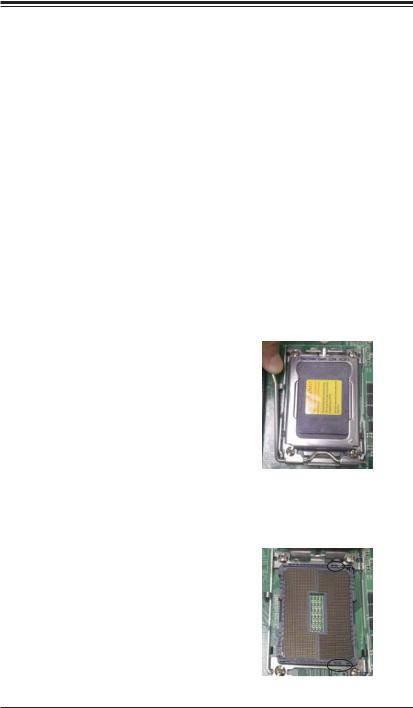
Installing the Processors
1.Begin by removing the cover plate that protects the CPU. Lift the lever on the CPU socket until it points straight up.
Caution! Please save the plastic cap. The serverboard must be shipped with the plastic cap properly installed to protect the CPU socket pins. Shipment without the plastic cap properly installed may cause damage to the socket pins
2. With the lever raised, lift open the silver CPU retention plate. Align the CPU keys with the socket keys.
2-2
Chapter 2: Installation
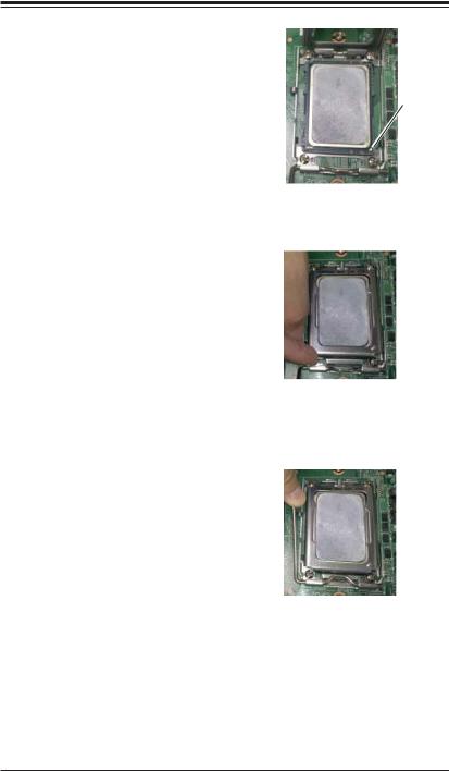
3. Use your thumb and your index finger |
|
|
to hold the CPU. Locate and align pin |
|
|
1 of the CPU socket with pin 1 of the |
|
|
CPU. Both are marked with a triangle. |
Triangle |
|
4. Align pin 1 of the CPU with pin 1 of the |
||
|
||
socket. Once aligned, carefully place |
|
|
the CPU into the socket. Do not drop |
|
|
the CPU on the socket, move the CPU |
|
|
horizontally or vertically or rub the CPU |
|
|
against the socket or against any pins |
|
|
of the socket, which may damage the |
|
|
CPU and/or the socket. |
|
5.With the CPU inserted into the socket, inspect the four corners of the CPU to make sure that it is properly installed and flush with the socket. Then, gently lower the silver CPU retention plate into place.
Caution: The CPU will only seat inside the socket in one direction. Make sure it is properly inserted before closing the load plate. If it doesn't close properly, do not force it as it may damage your CPU. Instead, open the load plate again and double-check that the CPU is aligned properly.
6.Carefully press the CPU socket lever down until it locks into its retention tab. For a dual-CPU system, repeat these steps to install another CPU into the CPU#2 socket.
Note: in single and dual-CPU configurations, memory must be installed in the DIMM slots associated with the installed CPU(s).
Note: see Chapter 6 for details on installing the air shroud.
Caution: Supermicro recommends that you utilize a Processor Installation/Removal tool to install or remore the processor from the serverboard without causing the processor or serverboard damage.
2-3

H8DG6/i(-F) SERVERBOARD USER'S MANUAL
Installing the Heatsinks
We recommend the use of active type heatsinks (except for 1U systems). Use any onboard fan header for the CPU's heatsink fan. To install the heatsink, please follow the installation instructions that are included with your heatsink package.
2-3 Mounting the Motherboard into a Chassis
All motherboards have standard mounting holes to fit different types of chassis. Make sure that the locations of all the mounting holes for both the motherboard and the chassis match. Although a chassis may have both plastic and metal mounting fasteners, metal ones are highly recommended because they ground the motherboard to the chassis. Make sure that the metal standoffs click in or are screwed in tightly.
Check the Compatibility of the Motherboard Ports and the I/O Shield
1.The H8DG6/i(-F) serverboard requires a chassis that can support a board of (LxW) 12" x 13" (305 x 330 mm) in size.
2.Make sure that the I/O ports on the motherboard align with their respective holes in the I/O shield at the rear of the chassis.
Mounting the Motherboard onto the Tray in the Chassis
1.Carefully mount the motherboard onto the motherboard tray by aligning the motherboard mounting holes with the raised metal standoffs in the tray.
2.Insert screws into all the mounting holes in the motherboard that line up with the standoffs.
3.Then use a screwdriver to secure the motherboard to the mainboard tray
– tighten until just snug (if too tight you might strip the threads). Metal screws provide an electrical contact to the motherboard ground to provide a continuous ground for the system.
Caution: Exercise extreme caution when installing or removing memory modules to prevent any possible damage.
2-4 Installing Memory
Installing Memory
1.Insert each memory module vertically into its slot, paying attention to the notch along the bottom of the module to prevent inserting the module incorrectly (see Figure 2-1).
2.Install to slots CPU1/DIMM1A, CPU1/DIMM2A, CPU1/DIMM3A and CPU1/
DIMM4A, etc. Always install in groups of four and in the numerical order of the DIMM slots. See support information below.
2-4
 Loading...