


 Loading...
SuperWorkstation
7049GP-TRT
USER’S MANUAL
Revision 1.0c

The information in this user’s manual has been carefully reviewed and is believed to be accurate. The vendor assumes no responsibility for any inaccuracies that may be contained in this document, and makes no commitment to update or to keep current the information in this manual, or to notify any person or organization of the updates. Please Note:
For the most up-to-date version of this manual, please see our website at www.supermicro.com.
Super Micro Computer, Inc. ("Supermicro") reserves the right to make changes to the product described in this manual at any time and without notice. This product, including software and documentation, is the property of Supermicro and/ or its licensors, and is supplied only under a license. Any use or reproduction of this product is not allowed, except as expressly permitted by the terms of said license.
IN NO EVENT WILL Super Micro Computer, Inc. BE LIABLE FOR DIRECT, INDIRECT, SPECIAL, INCIDENTAL, SPECULATIVE OR CONSEQUENTIAL DAMAGES ARISING FROM THE USE OR INABILITY TO USE THIS PRODUCT OR DOCUMENTATION, EVEN IF ADVISED OF THE POSSIBILITY OF SUCH DAMAGES. IN PARTICULAR, SUPER MICRO COMPUTER, INC. SHALL NOT HAVE LIABILITY FOR ANY HARDWARE, SOFTWARE, OR DATA STORED OR USED WITH THE PRODUCT, INCLUDING THE COSTS OF REPAIRING, REPLACING, INTEGRATING, INSTALLING OR RECOVERING SUCH HARDWARE, SOFTWARE, OR DATA.
Any disputes arising between manufacturer and customer shall be governed by the laws of Santa Clara County in the State of California, USA. The State of California, County of Santa Clara shall be the exclusive venue for the resolution of any such disputes. Supermicro's total liability for all claims will not exceed the price paid for the hardware product.
FCC Statement: This equipment has been tested and found to comply with the limits for a Class A digital device pursuant to Part 15 of the FCC Rules. These limits are designed to provide reasonable protection against harmful interference when the equipment is operated in a commercial environment. This equipment generates, uses, and can radiate radio frequency energy and, if not installed and used in accordance with the manufacturer’s instruction manual, may cause harmful interference with radio communications. Operation of this equipment in a residential area is likely to cause harmful interference, in which case you will be required to correct the interference at your own expense.
California Best Management Practices Regulations for Perchlorate Materials: This Perchlorate warning applies only to products containing CR (Manganese Dioxide) Lithium coin cells. “Perchlorate Material-special handling may apply. See www.dtsc.ca.gov/hazardouswaste/perchlorate”.
WARNING: This product can expose you to chemicals including
!lead, known to the State of California to cause cancer and birth defects or other reproductive harm. For more information, go to www.P65Warnings.ca.gov.
The products sold by Supermicro are not intended for and will not be used in life support systems, medical equipment, nuclear facilities or systems, aircraft, aircraft devices, aircraft/emergency communication devices or other critical systems whose failure to perform be reasonably expected to result in significant injury or loss of life or catastrophic property damage. Accordingly, Supermicro disclaims any and all liability, and should buyer use or sell such products for use in such ultra-hazardous applications, it does so entirely at its own risk. Furthermore, buyer agrees to fully indemnify, defend and hold Supermicro harmless for and against any and all claims, demands, actions, litigation, and proceedings of any kind arising out of or related to such ultra-hazardous use or sale.
Manual Revision 1.0c
Release Date: January 30, 2019
Unless you request and receive written permission from Super Micro Computer, Inc., you may not copy any part of this document. Information in this document is subject to change without notice. Other products and companies referred to herein are trademarks or registered trademarks of their respective companies or mark holders.
Copyright © 2019 by Super Micro Computer, Inc.
All rights reserved.
Printed in the United States of America
Preface
Preface
About this Manual
This manual is written for professional system integrators and PC technicians. It provides information for the installation and use of the SuperWorkstation. Installation and maintenance should be performed by experienced technicians only.
Please refer to the server specifications page on our website for updates on supported memory, processors and operating systems (www.supermicro.com).
Notes
For your system to work properly, please follow the links below to download all necessary drivers/utilities and the user’s manual for your server.
•Supermicro product manuals: http://www.supermicro.com/support/manuals/
•Product drivers and utilities: https://www.supermicro.com/wftp/driver
•Product safety info: http://www.supermicro.com/about/policies/safety_information.cfm
If you have any questions, please contact our support team at: support@supermicro.com.
This manual may be periodically updated without notice. Please check the Supermicro website for possible updates to the manual revision level.
Warnings
Special attention should be given to the following symbols used in this manual.
Warning! Indicates important information given to prevent equipment/property damage or personal injury.
 Warning! Indicates high voltage may be encountered when performing a procedure.
3

SuperWorkstation 7049GP-TRT User's Manual
|
Contents |
|
Chapter 1 Introduction |
|
|
1.1 |
Overview............................................................................................................................... |
7 |
1.2 |
Unpacking the System.......................................................................................................... |
7 |
1.3 |
System Features................................................................................................................... |
8 |
1.4 |
Server Chassis Features...................................................................................................... |
9 |
|
Control Panel....................................................................................................................... |
9 |
|
Front Features................................................................................................................... |
11 |
|
Rear Features.................................................................................................................... |
12 |
1.5 |
Motherboard Layout............................................................................................................ |
13 |
|
Quick Reference Table...................................................................................................... |
14 |
Chapter 2 Workstation Setup |
|
|
2.1 |
Overview............................................................................................................................. |
17 |
2.2 |
Preparing for Setup............................................................................................................. |
17 |
|
Choosing a Setup Location............................................................................................... |
17 |
|
General Precautions.......................................................................................................... |
17 |
Chapter 3 Maintenance and Component Installation |
|
|
3.1 |
Removing Power................................................................................................................. |
18 |
3.2 |
Accessing the System......................................................................................................... |
18 |
3.3 |
Motherboard Components.................................................................................................. |
19 |
|
Processor and Heatsink Installation.................................................................................. |
19 |
|
Overview of the Processor Socket Assembly.................................................................... |
20 |
|
Overview of the Processor Heatsink Module (PHM)......................................................... |
21 |
|
Attaching the Non-F Model Processor to the Narrow Processor Clip to Create the |
|
|
Processor Package Assembly........................................................................................... |
22 |
|
Removing the FAN Module .............................................................................................. |
23 |
|
Attaching the Non-F Model Processor Package Assembly to the Heatsink to Form the |
|
|
Processor Heatsink Module (PHM)................................................................................... |
24 |
|
Preparing the CPU Socket for Installation......................................................................... |
25 |
|
Removing the Dust Cover from the CPU Socket.............................................................. |
25 |
|
Installing the Processor Heatsink Module (PHM) ............................................................ |
26 |
|
Removing the Processor Heatsink Module (PHM) from the Motherboard........................ |
27 |
|
Installing Memory............................................................................................................... |
28 |
|
Motherboard Battery.......................................................................................................... |
29 |
4

Preface
|
Air Shroud...................................................................................................................... |
30 |
|
System Cooling.................................................................................................................. |
31 |
|
System Fan Failure............................................................................................................ |
31 |
|
Replacing System Fans..................................................................................................... |
31 |
Chapter 4 Motherboard Connections |
|
|
4.1 |
Power Connections............................................................................................................. |
33 |
4.2 |
Headers and Connectors.................................................................................................... |
34 |
4.3 |
Ports.................................................................................................................................... |
40 |
|
Rear I/O Ports................................................................................................................ |
40 |
4.4 |
Jumpers.............................................................................................................................. |
43 |
|
Explanation of Jumpers.................................................................................................. |
43 |
4.5 |
LED Indicators.................................................................................................................... |
46 |
Chapter 5 Software |
|
|
5.1 |
OS Installation..................................................................................................................... |
47 |
|
Installing the Windows OS for a RAID System................................................................. |
47 |
|
Installing Windows to a Non-RAID System....................................................................... |
47 |
5.2 |
Driver Installation................................................................................................................ |
48 |
5.3 |
SuperDoctor® 5................................................................................................................... |
49 |
5.4 |
IPMI..................................................................................................................................... |
50 |
Chapter 6 UEFI BIOS |
|
|
6.1 |
Introduction......................................................................................................................... |
51 |
|
Starting the Setup Utility.................................................................................................... |
51 |
6.2 |
Main Setup.......................................................................................................................... |
52 |
6.3 |
Advanced Setup Configurations......................................................................................... |
53 |
6.4 |
Event Logs.......................................................................................................................... |
87 |
6.5 |
IPMI.................................................................................................................................... |
89 |
6.6 |
Security............................................................................................................................... |
92 |
6.7 |
Boot..................................................................................................................................... |
95 |
6.8 |
Save & Exit......................................................................................................................... |
98 |
Appendix A BIOS Error Codes
Appendix B Standardized Warning Statements for AC Systems
Appendix C System Specifications
Appendix D UEFI BIOS Recovery Appendix E BSMI RoHS
5

SuperWorkstation 7049GP-TRT User's Manual
|
Contacting Supermicro |
Headquarters |
|
Address: |
Super Micro Computer, Inc. |
|
980 Rock Ave. |
|
San Jose, CA 95131 U.S.A. |
Tel: |
+1 (408) 503-8000 |
Fax: |
+1 (408) 503-8008 |
Email: |
marketing@supermicro.com (General Information) |
|
support@supermicro.com (Technical Support) |
Website: |
www.supermicro.com |
Europe |
|
Address: |
Super Micro Computer B.V. |
|
Het Sterrenbeeld 28, 5215 ML |
|
's-Hertogenbosch, The Netherlands |
Tel: |
+31 (0) 73-6400390 |
Fax: |
+31 (0) 73-6416525 |
Email: |
sales@supermicro.nl (General Information) |
|
support@supermicro.nl (Technical Support) |
|
rma@supermicro.nl (Customer Support) |
Website: |
www.supermicro.nl |
Asia-Pacific |
|
Address: |
Super Micro Computer, Inc. |
|
3F, No. 150, Jian 1st Rd. |
|
Zhonghe Dist., New Taipei City 235 |
|
Taiwan (R.O.C) |
Tel: |
+886-(2) 8226-3990 |
Fax: |
+886-(2) 8226-3992 |
Email: |
support@supermicro.com.tw |
Website: |
www.supermicro.com.tw |
6

Chapter 1: Introduction
Chapter 1
Introduction
1.1 Overview
This chapter provides a brief outline of the functions and features of the 7049GP-TRT. The 7049GP-TRT is based on the X11DPG-QT motherboard and the SC-747BTS-R2K20BP chassis.
In addition to the motherboard and chassis, several important parts that are included with the system are listed below.
Main Parts List
Description |
Part Number |
Quantity |
|
|
|
Hybrid backplane iPASS to 2 SATA cable Active CPU heatsink 4-pin PWM fan
Middle fan
4-pin PWM fan assembly
BPN-SAS3-747TQ-N4 1 CBL-0188L-02 2 SNK-P0070APS4 2 Fan-0114L4 2 FAN-0138L4 2 FAN-0082L4 2
1.2 Unpacking the System
Inspect the box the SuperServer 7049GP-TRT was shipped in and note if it was damaged in any way. If any equipment appears damaged, please file a damage claim with the carrier who delivered it.
Decide on a suitable location for the rack unit that will hold the server. It should be situated in a clean, dust-free area that is well ventilated. Avoid areas where heat, electrical noise and electromagnetic fields are generated. It will also require a grounded AC power outlet nearby.
Be sure to read the precautions and considerations noted in Appendix B.
7

SuperWorkstation 7049GP-TRT User's Manual
1.3 System Features
The following table provides you with an overview of the main features of the 7049GP-TRT.
Please refer to Appendix C for additional specifications.
System Features
Motherboard
X11DPG-QT
Chassis
SC-747BTS-R2K20BP
CPU
Intel® Xeon® Scalable Processors
Socket Type
Dual Socket P (LGA 3647)
Memory
Integrated memory controller embedded in the processor supports up to 2TB of 3DS Load Reduced DIMM (3DS LRDIMM), Load Reduced DIMM (LRDIMM), Registered DIMM (RDIMM), Non-Volatile DIMM (NV-DIMM) DDR4 (288-pin) ECC 2666/2400/2133 MHz modules in 16 slots
Chipset
Intel® C621 chipset
Expansion Slots
Four PCI Express 3.0 x16
Two PCI Express 3.0 x16 or HSSI (High Speed Serial Interface)
One PCI Express 3.0 x4 in x8 slot
Hard Drives
Eight hot-swap 3.5" drives
Power
2200W redundant power supply with PMBus
Form Factor
4U Rackmount/Tower
Dimensions
7.0 x 18.2 x 26.5 in. / 178 x 462 x 673 mm. (W x H x D)
8
Chapter 1: Introduction
1.4 Server Chassis Features
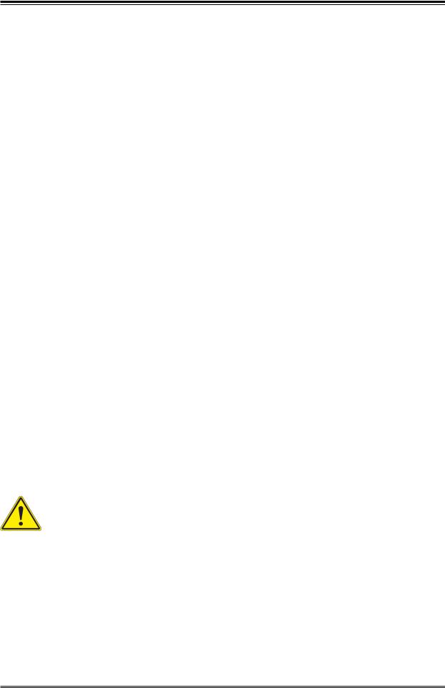
Control Panel
The switches and LEDs located on the control panel are described below. See Chapter 4 for details on the control panel connections.
1 |
2 |
|
|
|
|
7 |
8 |
9 |
|
3 |
4 |
5 |
6 |
||||
|
|
|
|
|
Figure 1-1. Control Panel View
9
SuperWorkstation 7049GP-TRT User's Manual
|
|
Control Panel Features |
|
|
|
|
|
Item |
Feature |
Description |
|
|
|
The main power switch is used to apply or remove power from the |
|
|
|
||
1 |
Power Button |
power supply to the server. Turning off system power with this button |
|
removes the main power but maintains standby power. To perform |
|||
|
|
many maintenance tasks, you must unplug system before servicing. |
|
2 |
Reset Button |
The reset button is used to reboot the system. |
|
3 |
HDD LED |
Indicates hard drive activity on the hard drive when flashing. |
|
4 |
NIC LED |
Indicates network activity on LAN when flashing. |
|
5 |
Information LED |
Alerts operator of several states. See table below for details. |
|
6 |
Power Fail |
Indicates a power failure to the system's power supply units. |
|
7 |
USB3.0 |
Two USB 3.0 ports. |
|
8 |
Line out |
Line out port. |
|
9 |
Mic |
Mic port. |
|
|
|
|
Information LED
Status
Continuously on and red Blinking red (1 Hz) Blinking red (0.25 Hz) Solid blue
Blinking blue
Description
An overheat condition has occurred.
(This may be caused by cable congestion.) Fan failure, check for an inoperative fan.
Power failure, check for a non-operational power supply.
Local UID has been activated. Use this function to locate the server in a rack mount environment.
Remote UID is on. Use this function to identify the server from a remote location.
10
Chapter 1: Introduction
Front Features
The SC-747BTS-R2K20BP is 4U rackmount/tower chassis See the illustration below for the features included on the front of the chassis.
1 |
2 |
3 |
|
|
Figure 1-2. Chassis Front View |
|
|
|
|
|
|
|
|
Front Chassis Features |
|
|
|
|
Item |
Feature |
|
Description |
1 |
Control Panel |
|
Front control panel (see preceding page). |
|
|||
2 |
Bezel Lock |
|
Locks the bezel for secure access. |
|
|||
3 |
Hot-swap Drive Bays |
|
Eight 3.5'' drive bays. |
|
|||
|
|
|
|
11
SuperWorkstation 7049GP-TRT User's Manual
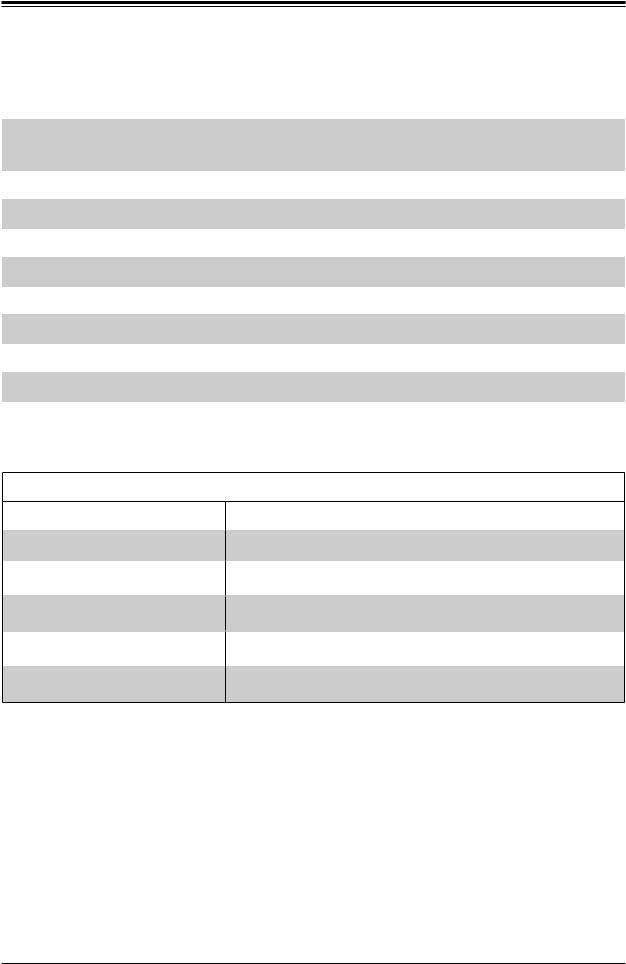
Rear Features
The illustration below shows the features included on the rear of the chassis.
|
|
6 |
8 |
1 |
|
|
|
5 |
|
|
|
2 |
3 |
4 |
7 |
|
|
|
9 |
Figure 1-3. Chassis Rear View
|
|
Rear Chassis Features |
|
|
|
|
|
Item |
Feature |
|
Description |
1 |
Power |
|
2x 2200W redundant power supply with PMBus |
|
|||
2 |
COM |
|
Serial Port |
|
|||
3 |
USB |
|
Two USB 3.0 ports and two USB 2.0 ports |
|
|||
4 |
LAN |
|
Two RJ45 10GBase-T ports |
|
|||
5 |
IPMI |
|
RJ45 Dedicated IPMI LAN port |
|
|||
6 |
FAN |
|
Two rear fans |
|
|||
7 |
Video |
|
VGA port |
|
|||
8 |
PCI-E |
|
Four PCI-E 3.0 x16 (double-width) slots |
|
|||
9 |
PCI-E |
|
Two PCI-E 3.0 x16 slots and one PCI-E 2.0 x4 slot |
|
|||
|
|
|
|
12

Chapter 1: Introduction
1.5 Motherboard Layout
Below is a layout of the X11DPG-QT with jumper, connector and LED locations shown. See the table on the following page for descriptions. For detailed descriptions, pinout information and jumper settings, refer to Chapter 4.
|
|
|
|
JUIDB1 |
VGA |
|
|
|
COM1 |
|
|
|
|
(UID) |
|
|
|
||
MAC CODE |
IPMI CODE |
JSDCARD1 |
LEDM1 |
LED2 |
|
LAN 2 |
LAN 1 |
USB 0/1 |
IPMI_LAN |
SAN MAC |
BAR CODE |
|
|
(UID-LED) |
|
|
|
|
|
|
|
|
|
|
|
|
|
|
|
|
DESIGNED IN USA |
|
|
BMC |
|
|
|
|
|
|
|
|
|
|
|
|
|
|
|
|
|
|
COM2 |
FAN C |
FAN D |
|
|
|
LAN |
|
|
|
|
|
|
|
|
|
|
|
|
|
|
||
|
|
|
|
|
|
|
|
|
|
|
|
|
|
|
USB 4/5 (3.0) |
|
|
|
|
||||
|
|
|
|
|
|
|
|
|
CTRL |
|
|
|
|
|
|
FAN 4 |
|
|
|
|
|||
|
|
|
|
|
|
|
|
|
|
|
|
|
|
|
|
|
|
|
|
|
|||
|
|
|
x16)0.3E-PCISLOT2(CPU1JPCIE2 |
x16)0.3E-PCISLOT4(CPU1JPCIE4 |
QT-X11DPG |
x16)0.3E-PCISLOT6(CPU2JPCIE6 |
x16)0.3E-PCISLOT8(CPU2JPCIE8 |
x16)0.3E-PCISLOT9(CPU1JPCIE9 |
|
|
SLOT10(CPU2 |
|
x8))(INx40.3E-PCISLOT11(CPU2JPCIE11 |
|
|
|
|
|
|
FAN 3 |
|
|
|
|
JPTG1 |
|
|
|
|
|
|
|
JTBT1 |
|
JPCIE10 |
|
|
|
|
|
|
|
|
|
|
|
|
|
|
|
|
|
|
|
|
|
|
|
|
|
|
|
|
|
|
|
|
|
|
||
|
JRK1 |
|
|
|
|
|
|
|
|
JNCSI1 |
|
|
|
|
|
|
|
|
|
|
|
||
|
|
|
|
|
|
|
|
|
|
|
|
|
|
|
|
|
|
|
|
|
|
||
|
|
S-UM12 |
|
|
02.REV:1 |
|
|
JHFI1 |
JHFI2 |
|
|
|
|
|
|
|
|
|
|
|
|
|
|
JIPMB1 |
|
|
|
|
|
|
|
|
|
|
|
|
|
|
|
|
|
|
|
|
|||
|
|
|
|
|
|
|
|
|
|
|
|
|
|
|
|
|
|
|
|
|
|||
|
|
|
|
|
|
|
|
|
|
|
|
|
|
|
|
|
|
|
|
|
|
||
|
JVRM_SEL1 |
|
|
|
|
|
|
|
|
E-PCI |
|
|
|
|
|
|
|
|
|
|
|
|
|
|
|
|
|
|
|
|
|
|
|
|
x16) 0.3 |
|
|
|
|
|
|
|
|
|
|
|
|
|
|
|
|
|
|
|
|
|
|
|
|
|
|
|
|
|
|
CPU2 |
|
|
|
|
|
|
|
|
|
|
|
|
|
JNVI2C1 |
JNVI2C2 |
|
|
|
|
|
|
|
|
|
|
|
|
|
|
|
JWD1 |
|
|
|
|
|
|
|
|
|
|
|
|
|
|
|
|
|
|
|
|
|
|
|
|
BIOS |
|
|
|
|
|
|
|
|
|
|
|
|
|
|
|
|
|
|
|
|
|
JSEN1 |
LICENSE |
|
|
|
|
|
|
|
|
|
|
P2 |
P2 |
P2 |
P2 |
|
|
|
|
|
|
|
|
|
|
|
|
|
|
|
|
|
|
|
|
|
|
|
|
|
|
||||||
|
|
|
|
|
|
|
|
|
DIMMF1-P1 |
DIMME1-P1 |
DIMMD1-P1 |
DIMMD2-P1 |
- |
- |
- |
- |
|
DIMMA2-P1 |
DIMMA1-P1 |
DIMMB1-P1 |
DIMMD2-P2 DIMMC1-P1 |
DIMMD1-P2 |
DIMMF1-P2 |
|
|
|
|
|
|
|
|
|
DIMMC1 |
DIMMB1 |
DIMMA1 |
DIMMA2 |
|
||||||||||
|
|
|
|
|
|
|
|
|
|
|
|
|
|
|
|
|
|
|
|
|
|
-P2 |
|
|
JSTBY1 |
|
|
|
|
|
|
|
|
|
|
|
|
|
|
|
|
|
|
|
DIMME1 |
|
|
|
|
|
|
|
|
|
|
|
|
|
|
|
|
|
|
|
|
|
|
|
|
||
|
|
|
|
|
|
|
|
|
|
|
|
|
|
|
|
|
|
|
|
|
|
FAN 6 |
|
|
|
|
|
|
|
M.2 CONNECOR |
|
|
|
|
|
|
|
|
|
|
|
|
|
|
|
JPI2C1 |
|
|
|
|
|
|
|
|
|
|
|
|
|
|
|
|
|
|
|
|
|
|
|
|
|
|
|
|
|
|
|
|
|
|
|
|
|
|
|
|
|
|
|
|
|
|
|
JPWR4 |
|
|
|
|
|
JBT1 |
|
|
|
|
|
|
|
|
|
|
|
|
|
|
|
|
|
JPWR3 |
|
|
S-SGPIO |
|
|
BT1 |
|
|
|
|
|
|
|
|
|
|
CPU1 |
|
|
|
|
|
|
|
|
|
|
|
|
|
|
|
|
|
|
|
|
|
|
|
|
|
|
|
|
JPWR2 |
|
||
|
|
|
|
|
|
|
|
|
|
|
|
|
|
|
|
|
|
|
|
|
|
||
JSD2 |
JSD1 |
|
|
PCH |
|
|
|
|
|
|
|
|
|
|
|
|
|
|
|
|
|
|
|
|
|
|
|
|
|
|
|
|
|
|
|
|
|
|
|
|
|
|
|
|
|
|
|
|
|
|
|
|
|
|
JTAG_HFI1 |
|
|
|
|
|
|
|
|
|
|
|
|
|
|
|
|
|
|
S-SATA4 |
|
|
|
|
JTPM1 |
|
|
|
|
|
|
|
|
|
|
|
|
|
|
|
|
|
|
|
|
|
|
|
|
|
|
|
|
|
|
|
|
|
|
|
|
|
|
|
|
|
|
|
|
|
|
|
|
|
|
|
|
|
|
|
|
|
|
|
|
|
|
JPWR1 |
|
S-SATA5 |
|
|
USB 8 (3.0) |
|
|
|
|
USB 2/3 |
|
|
|
USB 6/7 (3.0) |
I-SATA4~7 |
I-SATA0~3 |
JPME2 |
|
|||
|
|
|
SP1 |
|
FAN B |
JPAC1 |
AUDIO_FP |
JHD_AC1 |
LEDPWR |
|
FAN 5 FAN 1 |
|
|
JF1 |
|
|
|||
JL1 |
|
|
FAN A |
FAN 2 |
|||
|
|
JSPDIF_IN1 |
|
|
|||
|
|
|
|
|
Figure 1-4. Motherboard Layout
13

SuperWorkstation 7049GP-TRT User's Manual
Quick Reference Table
Jumper |
Description |
Default Setting |
|
JBT1 |
CMOS Clear |
Open (Normal) |
|
JHD_AC1 |
AC97/High Definition Audio Enable |
Off (HD Enabled) |
|
JPAC1 |
Audio Enable |
Pins 1-2 (Enabled) |
|
JPME2 |
ME Manufacturing Mode |
Pins 1-2 |
(Normal) |
JPTG1 |
Onboard 10Gb LAN1/2 Enable/Disable |
Pins 1-2 |
(Enabled) |
JVRM_SEL1 |
VRM_I2C Jumper |
Pins 1-2 |
(Normal) |
JWD1 |
Watch Dog Timer Reset |
Pins 1-2 |
(Reset) |
Connector |
Description |
|
AUDIO_FP |
Front Panel Audio Header |
|
BT1 |
Onboard Battery |
|
COM1 |
COM Port (COM1) on the I/O Backplane |
|
COM2 |
COM Header |
|
FAN1 ~ FAN6, FANA, |
System/CPU Fan Headers (FAN5: CPU1 Fan, FAN6: CPU2 Fan) |
|
FANB, FANC, FAND |
||
|
||
IPMI_LAN |
Dedicated IPMI LAN Port |
|
I-SATA0~3, I-SATA4~7 |
Intel® PCH SATA 3.0 Ports (0-3, 4-7) |
|
JF1 |
Front Control Panel Header |
|
JIPMB1 |
4-pin BMC External IC Header (for an IPMI card) |
|
JL1 |
Chassis Intrusion Header |
|
JNCSI1 |
NC-SI Header for IPMI Support |
|
JNVI2C1 |
VPP Header for the NVMe Add-on Card on PCI-E Slot 9 |
|
JNVI2C2 |
VPP Header for the NVMe Add-on Card on PCI-E Slot 10 |
|
JPI2C1 |
Power Supply SMBus I2C Header |
|
JPWR1 |
24-pin ATX Power Connector |
|
JPWR2/JPWR3 |
12V 8-pin CPU Power Connector (To provide alternative power for special enclosure when the 24- |
|
pin ATX power is not in use.) |
||
|
||
JPWR4 |
12V 4-pin Power Connectors |
|
JRK1 |
RAID_Key for Onboard SATA Devices |
|
JSD1/JSD2 |
SATA DOM Power Connectors 1/2 |
|
JSDCARD1 |
Micro SD Card Slot |
|
JSEN1 |
Inlet Sensor Header |
|
JSPDIF_IN1 |
Sony/Philips Digital Interface Audio Input Header |
14

Chapter 1: Introduction
Connector |
Description |
|
JSTBY1 |
Standby Power Connector |
|
JTAG_HFI1 |
HFI Debug Port for Fabric CPU |
|
JTBT1 |
General Purpose Header for Thunderbolt Add-on Card |
|
JTPM1 |
Trusted Platform Module/Port 80 connector |
|
JUIDB1 |
UID (Unit Identifier) Switch |
|
LAN1/2 |
LAN Ports |
|
M.2 CONNECTOR |
PCI-E M.2 Connector, small form factor devices and other portable devices for High speed NVMe |
|
SSDs |
||
|
||
S-SATA4/S-SATA5 |
SATA 3.0 Ports with Power-pin Built-in w/support of SuperDOM (Device-On Module) |
|
S-SGPIO |
Serial Link General Purpose I/O Header |
|
SP1 |
Internal Speaker/Buzzer |
|
USB 0/1 |
Back Panel USB 2.0 Ports |
|
USB 2/3 |
Front Access USB 2.0 Header |
|
USB 4/5 |
Back Panel USB 3.0 Ports |
|
USB 6/7 |
Front Access USB 3.0 Header |
|
USB 8 |
USB 3.0 Type A Header |
|
VGA |
VGA Port (Back Panel) |
LED |
Description |
Status |
LED2 |
UID (Unit Identifier) LED |
Solid Blue: Unit Identified |
LEDM1 |
BMC Heartbeat LED |
Blinking Green: BMC Normal |
LEDPWR |
Onboard Power LED |
Solid Green: Power On |
15

SuperWorkstation 7049GP-TRT User's Manual
|
|
|
|
|
JPCIE8 |
|
x16 |
32GB/s |
32GB/s |
x 16 |
JPCIE6 |
|
|
VCCP1&2 |
|
|
|
|
||||
|
|
|
|
|
Slot 8 |
|
|
|
|
|
|
|
|
Slot 6 |
|
|
|
|
|
|
||
|
|
|
|
|
PCIE 3.0 x16 |
|
|
|
|
|
|
PCIE 3.0 x16 |
|
|
VR13 |
|
|
|
|
|||
|
|
|
|
|
|
|
|
|
|
|
|
|
|
|
|
|
|
6+1 PHASE |
|
|
|
|
|
|
|
|
|
JPCIE10 |
|
x16 |
32GB/s |
|
|
x 4 |
JPCIE11 |
|
|
|
205W |
|
|
|
|
||
|
|
|
|
|
|
|
|
|
|
|
|
|
|
|
|
|||||||
|
|
|
|
|
Slot 10 |
|
|
|
|
|
|
|
Slot 11 |
|
|
|
|
|
|
|
|
|
|
|
|
|
|
PCIE 3.0 x16 |
|
|
|
|
|
|
PCIE 3.0 x4 |
|
|
|
|
|
|
|
|||
#1 |
|
#1 |
|
#1#2 |
D |
|
PE3 |
PE2 |
PE1 |
DMI |
A |
|
#2#1 |
|
#1 |
|
#1 |
|
|
|
|
|
|
|
|
|
|
|
|
|
|
|
|
|
|
|
|
|
|
|
|
|
|
||
DIMM |
F |
DIMM |
E |
DIMM |
|
|
|
CPU 2 |
|
|
DIMM |
B |
DIMM |
C |
DIMM |
|
|
|
|
|||
|
|
|
|
|
|
|
|
|
|
|
|
|
|
|
||||||||
DDR4 |
|
DDR4 |
|
DDR4 |
|
|
P2 |
P1 |
P0 |
|
DDR4 |
|
DDR4 |
|
DDR4 |
|
|
|
|
|||
|
|
|
|
|
|
|
|
|
|
|
|
|
|
|
||||||||
|
|
|
|
|
|
|
|
UPI |
UPI |
UPI |
|
|
|
|
|
|
|
|
|
|
|
|
#1 |
|
#1 |
|
#1#2 |
D |
|
P2 |
|
P0 |
P0 |
A |
|
#1#2 |
|
#1 |
|
#1 |
|
|
|
|
|
|
|
|
|
|
|
|
|
|
|
|
|
|
|
|
|
|
|
|
|
|
||
DIMM |
F |
DIMM |
E |
DIMM |
|
|
|
CPU 1 |
|
|
DIMM |
B |
DIMM |
C |
DIMM |
|
|
|
|
|||
|
|
|
|
|
|
|
|
|
|
|
|
|
|
|
||||||||
DDR4 |
|
DDR4 |
|
DDR4 |
|
|
PE3 |
PE2 |
PE1 |
DMI |
|
DDR4 |
|
DDR4 |
|
DDR4 |
|
|
|
|
||
|
|
|
|
|
|
|
|
|
|
|
|
|
|
|
|
|
|
|
||||
|
|
JPCIE9 |
|
|
|
|
|
|
|
|
|
|
|
|
x4 |
|
|
M.2 CONN |
|
|
|
|
|
|
|
x16 |
|
|
|
|
|
|
|
|
|
|
|
|
|
PCIE 3.0 x4 |
|
|
|
||
|
|
|
Slot 9 |
|
|
|
|
|
|
|
|
|
|
|
x4 |
|
|
|
10G |
JLAN1 |
|
|
|
|
PCIE 3.0 x16 |
|
|
|
|
|
|
|
|
|
|
|
|
|
|
|
|||||
|
|
|
|
|
|
|
|
|
|
|
|
|
|
|
|
|
|
|
X550 |
10G |
RJ45 |
|
|
|
|
|
|
|
|
|
|
|
|
|
|
|
|
|
|
|
|
JLAN2 |
|
||
|
|
|
JPCIE4 |
|
x16 |
|
|
|
|
|
|
PET [0,1,2,3] |
SATA Gen3 [0..3] |
|
I-SATA-0~3 |
|
|
NC-SI |
RJ45 |
|
||
|
|
|
Slot 4 |
|
|
|
|
|
|
|
|
|
IPASS CONN |
|
|
|
|
|||||
|
|
PCIE 3.0 x16 |
|
|
|
|
|
|
|
|
|
|
|
|
|
|
|
To BMC RMII port |
||||
|
|
|
|
|
|
|
|
|
PET [4,5,6,7] |
|
|
|
I-SATA-4~7 |
|
|
|
||||||
|
|
|
|
|
|
|
|
|
|
|
|
SATA Gen3 [4..7] |
|
|
|
|
|
|
||||
|
|
|
JPCIE2 |
|
x16 |
|
|
|
|
|
|
|
|
|
IPASS CONN |
|
|
|
|
|
||
|
|
|
Slot 2 |
|
|
|
|
NC-SI(RMII) |
|
|
DMI |
|
sSATA Gen3 [4..5] |
|
S-SATA4 |
|
|
|
|
|
||
|
|
PCIE 3.0 x16 |
EXT CONN |
UL1 |
|
|
PCH |
|
|
S-SATA5 |
|
|
|
|
|
|||||||
|
|
|
|
|
|
JNCSI1 |
|
|
|
|
|
HD LINK |
|
ALC888 |
AUDIO FP |
|
|
|
|
|||
|
|
|
|
|
|
|
|
|
|
|
|
PET9 |
|
|
|
|
|
|
|
|||
|
|
|
BMC SPI |
|
|
|
|
|
|
|
|
USB2.0 [2..5] |
|
|
port 1,2(USB3.0) |
|
|
|
|
|||
|
|
|
|
|
|
|
|
|
|
|
|
|
|
|
|
|
|
|||||
64MB BIOS |
|
MUX |
|
|
|
|
|
|
|
|
|
USB2.0 [7..12] |
|
|
+ |
|
|
|
port 5(USB3.0) |
|||
|
PCH SPI |
|
|
|
|
BMC |
|
SPI |
|
|
port 4,5(USB2.0) port 11,12(USB2.0) port 3,4(USB3.0) |
|
|
|||||||||
SPI FLASH |
|
|
|
|
|
|
|
|
USB3.0 [1..5] |
|
|
|
+ |
port 8,9(USB2.0) |
+ |
|||||||
|
|
|
|
|
|
|
|
|
AST2500 |
|
|
USB2.0 [7] |
ESPI |
|
|
|
port 2,3(USB2.0) |
port 10(USB2.0) |
||||
|
|
|
|
|
32MB BMC |
|
|
|
|
|
|
|
HDR 2x10 |
HDR 2x5 |
|
|||||||
|
|
|
|
|
|
|
|
|
|
|
|
|
|
|
|
|
|
|||||
|
|
|
|
|
SPI FLASH |
|
|
|
|
|
|
|
|
|
REAR (USB2.0) REAR(USB3.0) |
(USB3.0) |
(USB2.0) |
TYPE A(USB3.0) |
||||
|
|
|
|
|
|
|
|
|
|
|
|
|
|
|
|
|
|
|
|
|||
|
|
|
|
|
|
DDR4 |
|
|
|
|
|
|
|
|
|
TPM Header |
|
|
|
|
|
|
|
|
|
|
|
|
|
|
|
|
|
PHY |
|
|
IPMI LAN |
|
|
|
|
|
|
|
|
|
|
|
|
|
|
|
|
|
|
|
|
|
|
|
|
|
|
|
|
|
||
|
|
|
|
|
|
|
|
|
|
|
|
RTL8211E |
RJ45 |
|
|
|
|
|
|
|
||
|
|
|
|
|
|
VGA |
|
|
HWM |
|
COM1 |
|
|
|
|
|
|
|
|
|
||
|
|
|
|
|
|
|
|
|
|
|
|
|
|
|
|
|
|
|
|
|||
|
|
|
|
|
|
|
|
|
|
|
|
COM2 |
|
|
|
|
|
|
|
|
|
|
Figure 1-5. Intel® C621 Chipset: System Block Diagram
Note: This is a general block diagram and may not exactly represent the features on your motherboard. See the System Specifications appendix for the actual specifications of your motherboard.
16

Chapter 2: Server Installation
Chapter 2
Workstation Setup
2.1 Overview
This chapter provides advice setting up your system. If your system is not already fully integrated with processors, system memory etc., refer to Chapter 3 for details on installing those specific components.
Caution: Electrostatic Discharge (ESD) can damage electronic components. To prevent such damage to PCBs (printed circuit boards), it is important to use a grounded wrist strap, handle all PCBs by their edges and keep them in anti-static bags when not in use.
2.2 Preparing for Setup
Please read this section in its entirety before you begin the installation.
Choosing a Setup Location
•The system should be situated in a clean, dust-free area that is well ventilated. Avoid areas where heat, electrical noise and electromagnetic fields are generated.
•Leave enough clearance in front and back of the system to allow sufficient airflow and access when servicing.
•This product should be installed only in a Restricted Access Location (dedicated equipment rooms, service closets, etc.).
•This product is not suitable for use with visual display workplace devices according to §2 of the German Ordinance for Work with Visual Display Units.
General Precautions
•Review the electrical and general safety precautions in Appendix B.
•Use a regulating uninterruptible power supply (UPS) to protect the server from power surges and voltage spikes and to keep your system operating in case of a power failure.
•Allow any drives and power supply modules to cool before touching them.
17

SuperWorkstation 7049GP-TRT User's Manual
Chapter 3
Maintenance and Component Installation
This chapter provides instructions on installing and replacing main system components. To prevent compatibility issues, only use components that match the specifications and/or part numbers given.
Installation or replacement of most components require that power first be removed from the system. Please follow the procedures given in each section.
3.1 Removing Power
Use the following procedure to ensure that power has been removed from the system. This step is necessary when removing or installing non hot-swap components or when replacing a non-redundant power supply.
1.Use the operating system to power down the system.
2.After the system has completely shut-down, disconnect the AC power cords from the power strip or outlet.
3.Disconnect the power cords from the power supply modules.
3.2Accessing the System
The CSE-747BTS-R2K20BP chassis features two removable side covers, allowing access to the interior.
Removing the Side Covers
1.Remove the two screws securing the left side cover to the chassis.
2.Slide the left cover toward the rear of the chassis.
3.Lift the left cover from the chassis.
4.Remove the three screws securing the right side cover to the chassis.
5.Slide the right cover toward the rear of the chassis.
6.Insert the expansion (add-on) card into the riser card.
Caution: Except for short periods of time, do not operate the server without the cover in place.
The chassis cover must be in place to allow for proper airflow and to prevent overheating.
18

Chapter 3: Maintenance and Component Installation
3.3 Motherboard Components
Processor and Heatsink Installation
Follow the procedures in this section to install a processor (CPU) and heatsink onto the motherboard mounted in the chassis.
Warning: When handling the processor package, avoid placing direct pressure on the label area of the CPU or CPU socket. Also, improper CPU installation or socket misalignment can cause serious damage to the CPU or motherboard which may result in RMA repairs. Please read and follow all instructions thoroughly before installing your CPU and heatsink.
Notes:
•When receiving a motherboard without a processor pre-installed, make sure that the plastic protective socket cover is in place and none of the socket pins are bent; otherwise, contact your retailer immediately.
•Use an Intel-certified multi-directional heatsink.
•Refer to the Supermicro website for updates on CPU support.
•Always connect the power cord last, and always remove it before adding, removing, or changing any hardware components. Please note that the processor and heatsink should be assembled together first to form the Processor Heatsink Module (PHM), and then install the entire PHM into the CPU socket.
Note: All graphics, drawings, and pictures shown in this manual are for illustration only. The components that came with your machine may or may not look exactly the same as those shown in this manual.
19

SuperWorkstation 7049GP-TRT User's Manual
Overview of the Processor Socket Assembly
The processor socket assembly contains 1) the Intel 81xx/61xx/51xx/41xx/31xx processor, 2) the narrow processor clip, 3) the dust cover, and 4) the CPU socket.
1. The 81xx/61xx/51xx/41xx/31xx Processor
(The 81xx/61xx/51xx/41xx/31xx Processor)
2. Narrow Processor Clip (the plastic processor package carrier used for the CPU)
(for the non-F Model)
3. Dust Cover
4. CPU Socket
Note: Be sure to cover the CPU socket with the dust cover when the CPU is not installed.
20
Chapter 3: Maintenance and Component Installation
Overview of the Processor Heatsink Module (PHM)
The Processor Heatsink Module (PHM) contains 1) a heatsink, 2) a narrow processor clip, and 3) the 81xx/61xx/51xx/41xx/31xx processor.
1. Heatsink
2. Narrow Processor Clip
3. Intel Processor
21
SuperWorkstation 7049GP-TRT User's Manual
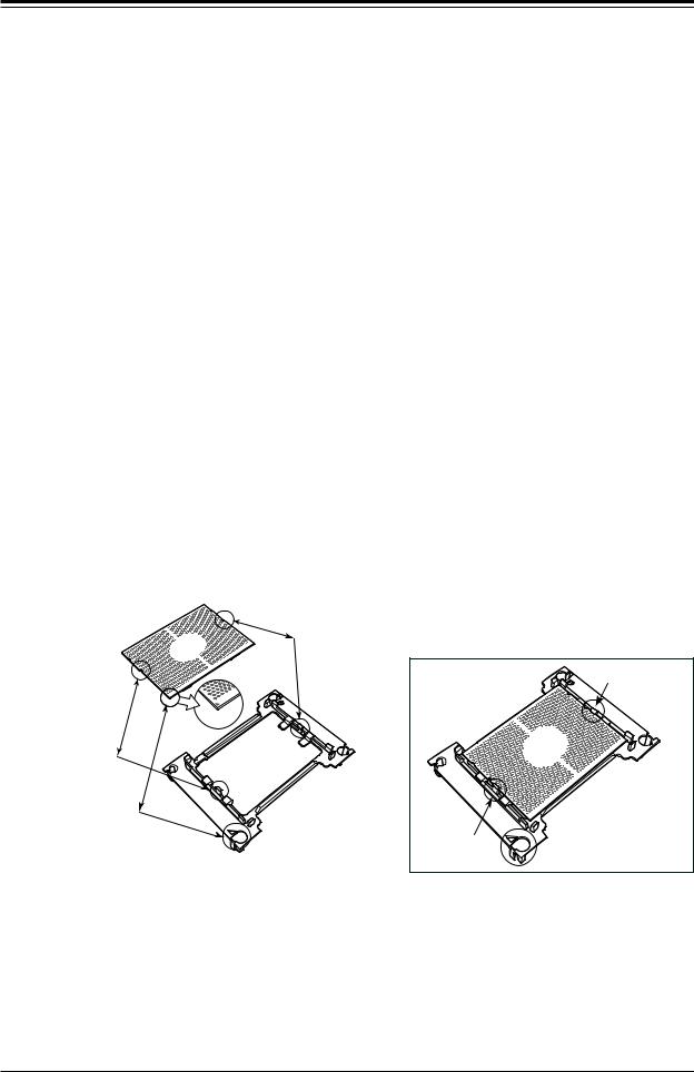
Attaching the Non-F Model Processor to the Narrow Processor Clip to Create the Processor Package Assembly
To properly install the CPU into the narrow processor clip, please follow the steps below.
1.Locate pin 1 (notch A), which is the triangle located on the top of the narrow processor clip. Also locate notch B and notch C on the processor clip.
2.Locate pin 1 (notch A), which is the triangle on the substrate of the CPU. Also, locate notch B and notch C on the CPU as shown below.
3.Align pin 1 (the triangle on the substrate) of the CPU with pin 1 (the triangle) of the narrow processor clip. Once they are aligned, carefully insert the CPU into the processor clip by sliding notch B of the CPU into notch B of the processor clip, and sliding notch C of the CPU into notch C of the processor clip.
4.Examine all corners of the CPU to ensure that it is properly seated on the processor clip. Once the CPU is securely attached to the processor clip, the processor package assembly is created.
Note: Please exercise extreme caution when handling the CPU. Do not touch the CPU LGA-lands to avoid damaging the LGA-lands or the CPU. Be sure to wear ESD gloves when handling components.
CPU (Upside Down) w/CPU LGA Lands up
C
Align Notch C of the CPU
and Notch C of the Processor Clip
B |
|
|
Allow Notch C to |
|
|
|
latch on to CPU |
A |
|
|
C |
Pin 1 |
C |
|
|
|
|
|
|
Align Notch B of the CPU |
|
|
|
and Notch B of the Processor Clip |
|
|
|
B |
CPU/Heatsink Package |
B |
|
|
|
||
(Upside Down) |
|
|
|
Align CPU Pin 1 |
|
|
|
A |
|
Allow Notch B to |
|
|
latch on to CPU |
A |
|
|
|
|
Processor Package Carrier (w/CPU mounted on the Processor Clip)
22

Chapter 3: Maintenance and Component Installation
Removing the FAN Module
1.Unplug the fan module connector from the motherboard fan connector.
2.Remove the screw on the fan module to release it from the heatsink.
23
SuperWorkstation 7049GP-TRT User's Manual
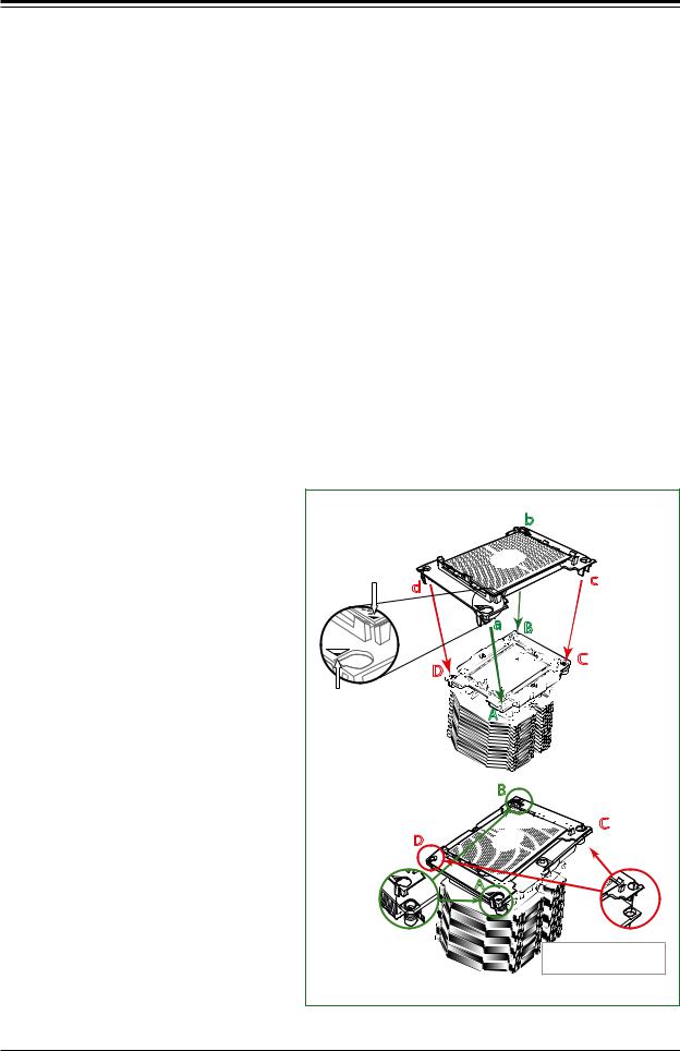
Attaching the Non-F Model Processor Package Assembly to the Heatsink to Form the Processor Heatsink Module (PHM)
After you have made a processor package assembly by following the instructions on the previous page, please follow the steps below to mount the processor package assembly onto the heatsink to create the Processor Heatsink Module (PHM).
1.Locate "CPU 1" on the heatsink label and the triangular corner next to it on the heatsink.
With your index finger pressing against the screw at this triangular corner, carefully hold and turn the heatsink upside down with the thermal-grease side facing up. Remove the protective thermal film if present, and apply the proper amount of the thermal grease as needed. (Skip this step if you have a new heatsink because the necessary thermal grease is pre-applied in the factory.)
2.Holding the processor package assembly at the center edge, turn it upside down. With the thermal-grease side facing up, locate the hollow triangle located at the corner of the processor carrier assembly ("a" in the graphic). Note a larger hole and plastic mounting clicks located next to the hollow triangle. Also locate another set of mounting clicks and
a larger hole at the diagonal corner of the same (reverse) side of the processor carrier assembly ("b" in the graphic).
3.With the back of heatsink and the reverse side of the processor
package assembly facing up, align the triangular corner on the heatsink ("A" in the graphic) against the mounting clips next to the hollow triangle ("a") on the processor package assembly.
4.Also align the triangular corner ("B") at the diagonal side of the heatsink with the corresponding clips on the processor package assembly ("b").
5.Once the mounting clips on the processor package assembly are properly aligned with the corresponding holes on the back of heatsink, securely attach the
heatsink to the processor package assembly by snapping the mounting clips at the proper places on the heatsink to create the processor heatsink module (PHM).
Non-Fabric CPU and Processor Clip
(Upside Down) |
b |
|
Triangle on the CPU |
d |
c |
|
|
|
|
a |
B |
|
D |
C |
|
|
|
Triangle on the |
|
|
Processor Clip |
|
A |
|
|
|
Heatsink |
|
|
(Upside Down) |
|
|
D
On Locations (A, B),
the notchessnap onto the heatsink’s sides
B |
On Locations of (C, D), the notches |
snap onto the heat sink’s |
|
|
mounting holes |


 C
C
A


Make sure Mounting
Notches snap into place
24
Chapter 3: Maintenance and Component Installation
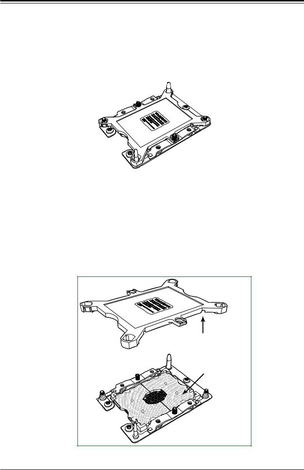
Preparing the CPU Socket for Installation
This motherboard comes with the CPU socket pre-assembled in the factory. The CPU socket contains 1) a dust cover, 2) a socket bracket, 3) the CPU (P0) socket, and 4) a back plate. These components are pre-installed on the motherboard before shipping.
CPU Socket w/Dust Cover On
Removing the Dust Cover from the CPU Socket
Remove the dust cover from the CPU socket, exposing the CPU socket and socket pins as shown on the illustration below.
Note: Do not touch the socket pins to avoid damaging them, causing the CPU to malfunction.
Dusk Cover
Remove the dust cover from |
the CPU socket. Do not |
touch the socket pins! |
Socket Pins |
25 |
SuperWorkstation 7049GP-TRT User's Manual
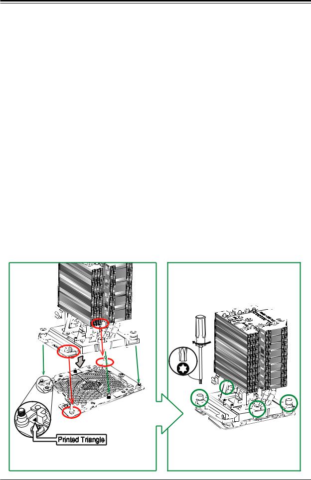
Installing the Processor Heatsink Module (PHM)
1.Once you have assembled the processor heatsink module (PHM) by following the instructions listed on page 29 or page 30, you are ready to install the processor heatsink module (PHM) into the CPU socket on the motherboard. To install the PHM into the CPU socket, follow the instructions below.
2.Locate the triangle (pin 1) on the CPU socket, and locate the triangle (pin 1) at the corner of the PHM that is closest to "1." (If you have difficulty locating pin 1 of the PHM, turn the PHM upside down. With the LGA-lands side facing up, you will note the hollow triangle located next to a screw at the corner. Turn the PHM right side up, and you will see a triangle marked on the processor clip at the same corner of hollow triangle.)
3.Carefully align pin 1 (the triangle) on the PHM against pin 1 (the triangle) on the CPU socket.
4.Once they are properly aligned, insert the two diagonal oval holes on the heatsink into the guiding posts.
5.Using a T30 Torx-bit screwdriver, install four screws into the mounting holes on the socket to securely attach the PHM onto the motherboard starting with the screw marked "1" (in the sequence of 1, 2, 3, and 4).
Note: Do not use excessive force when tightening the screws to avoid damaging the LGA-lands and the processor.
Oval C
|
Large |
Oval D |
Guide |
Post |
Small Guide Post
Printed Triangle
Mounting the Processor Heatsink Module into the CPU socket (on the motherboard)
Use a torque of 12 lbf
T30 Torx Driver
#4 |
#2 |
#1 |
|
|
#3 |
Tighten the screws in the sequence of 1, 2, 3, 4 (top 3 quarter view)
26

Chapter 3: Maintenance and Component Installation
Removing the Processor Heatsink Module (PHM) from the Motherboard
Before removing the processor heatsink module (PHM), unplug power cord from the power outlet.
1.Using a T30 Torx-bit screwdriver, turn the screws on the PHM counterclockwise to loosen them from the socket, starting with screw marked #4 (in the sequence of 4, 3, 2, 1).
2.After all four screws are removed, wiggle the PHM gently and pull it up to remove it from the socket.
Note: To properly remove the processor heatsink module, be sure to loosen and remove the screws on the PHM in the sequence of 4, 3, 2, 1 as shown below.
#4 |
#2 |
#1 |
|
|
#3 |
|
Removing the screws in |
|
the sequence of 4, 3, 2, 1 |
Printed Triangle on Motherboard |
|
CPU Socket
After removing the screws, lift the Processor Heatsink Module off the CPU socket.
27
SuperWorkstation 7049GP-TRT User's Manual
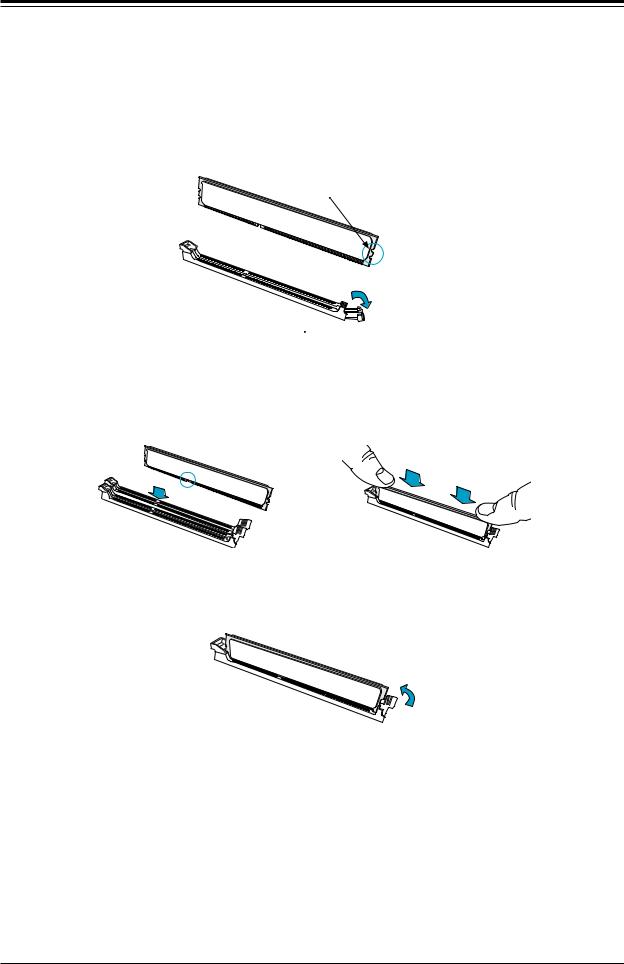
Installing Memory
1.Remove power from the system as described in Section 3.1.
2.Starting with the slot in the order described previously, push the release tab outward to unlock it.
Notch
Release Tab 
3.Align the key of the DIMM with the receptive point on the memory slot and with your thumbs on both ends of the module, press it straight down into the slot until the module snaps into place.
Press both ends straight
 down into the memory slot.
4. Press the release tab to the locked position to secure the DIMM module into the slot.
5.Repeat the procedure for the remaining DIMM modules in the order detailed in the previous section.
To remove a DIMM module, unlock the release tabs then pull the module from the slot.
28
Chapter 3: Maintenance and Component Installation
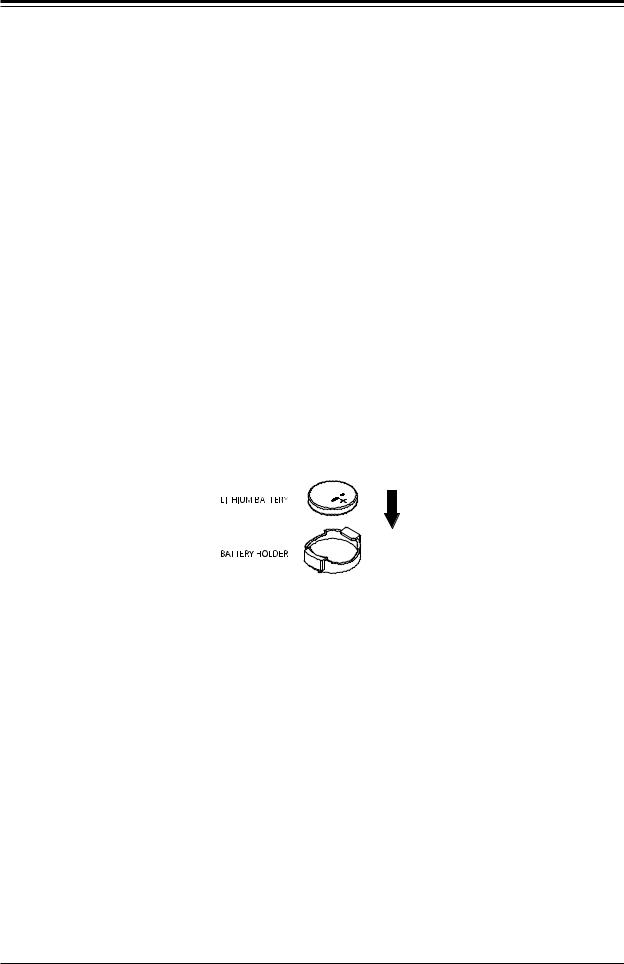
Motherboard Battery
The motherboard uses non-volatile memory to retain system information when system power is removed. This memory is powered by a lithium battery residing on the motherboard.
Replacing the Battery
1.Remove power from the system as described in section 3.1 and remove the node from the chassis.
2.Push aside the small clamp that covers the edge of the battery. When the battery is released, lift it out of the holder.
3.To insert a new battery, slide one edge under the lip of the holder with the positive (+) side facing up. Then push the other side down until the clamp snaps over it.
Note: Handle used batteries carefully. Do not damage the battery in any way; a damaged battery may release hazardous materials into the environment. Do not discard a used battery in the garbage or a public landfill. Please comply with the regulations set up by your local hazardous waste management agency to dispose of your used battery properly.
Figure 3-1. Installing the Onboard Battery
Warning: There is a danger of explosion if the onboard battery is installed upside down (which reverses its polarities). This battery must be replaced only with the same or an equivalent type recommended by the manufacturer (CR2032).
29

SuperWorkstation 7049GP-TRT User's Manual
Air Shroud
The air shroud is used to concentrate airflow to maximize fan efficiency. The air shroud does not require screws to set up.
Installing the Air Shroud
1.Lay the chassis on a flat, stable surface and remove the chassis cover.
2.If necessary, move any cables that interfere with the air shroud placement.
3.Place the air shroud in the chassis. The air shroud fits just behind the three fans in the fan rack. Slide the air shroud into the grooves just behind the fan rack.
4.Reroute any cables that were moved and replace the chassis cover.
Figure 3-2. Installing the Air Shroud
30
Loading...