


 Loading...
SuperStorageServer®
SSG-6019P-ACR12L
USER’S MANUAL
Revision 1.0a

The information in this User’s Manual has been carefully reviewed and is believed to be accurate. The vendor assumes no responsibility for any inaccuracies that may be contained in this document, and makes no commitment to update or to keep current the information in this manual, or to notify any person or organization of the updates. Please Note:
For the most up-to-date version of this manual, please see our website at www.supermicro.com.
Super Micro Computer, Inc. ("Supermicro") reserves the right to make changes to the product described in this manual at any time and without notice. This product, including software and documentation, is the property of Supermicro and/ or its licensors, and is supplied only under a license. Any use or reproduction of this product is not allowed, except as expressly permitted by the terms of said license.
IN NO EVENT WILL Super Micro Computer, Inc. BE LIABLE FOR DIRECT, INDIRECT, SPECIAL, INCIDENTAL, SPECULATIVE OR CONSEQUENTIAL DAMAGES ARISING FROM THE USE OR INABILITY TO USE THIS PRODUCT OR DOCUMENTATION, EVEN IF ADVISED OF THE POSSIBILITY OF SUCH DAMAGES. IN PARTICULAR, SUPER MICRO COMPUTER, INC. SHALL NOT HAVE LIABILITY FOR ANY HARDWARE, SOFTWARE, OR DATA STORED OR USED WITH THE PRODUCT, INCLUDING THE COSTS OF REPAIRING, REPLACING, INTEGRATING, INSTALLING OR RECOVERING SUCH HARDWARE, SOFTWARE, OR DATA.
Any disputes arising between manufacturer and customer shall be governed by the laws of Santa Clara County in the State of California, USA. The State of California, County of Santa Clara shall be the exclusive venue for the resolution of any such disputes. Supermicro's total liability for all claims will not exceed the price paid for the hardware product.
FCC Statement: This equipment has been tested and found to comply with the limits for a Class A digital device pursuant to Part 15 of the FCC Rules. These limits are designed to provide reasonable protection against harmful interference when the equipment is operated in a commercial environment. This equipment generates, uses, and can radiate radio frequency energy and, if not installed and used in accordance with the manufacturer’s instruction manual, may cause harmful interference with radio communications. Operation of this equipment in a residential area is likely to cause harmful interference, in which case you will be required to correct the interference at your own expense.
California Best Management Practices Regulations for Perchlorate Materials: This Perchlorate warning applies only to products containing CR (Manganese Dioxide) Lithium coin cells. “Perchlorate Material-special handling may apply. See www.dtsc.ca.gov/hazardouswaste/perchlorate”.
WARNING: This product can expose you to chemicals including
!lead, known to the State of California to cause cancer and birth defects or other reproductive harm. For more information, go to www.P65Warnings.ca.gov.
The products sold by Supermicro are not intended for and will not be used in life support systems, medical equipment, nuclear facilities or systems, aircraft, aircraft devices, aircraft/emergency communication devices or other critical systems whose failure to perform be reasonably expected to result in significant injury or loss of life or catastrophic property damage. Accordingly, Supermicro disclaims any and all liability, and should buyer use or sell such products for use in such ultra-hazardous applications, it does so entirely at its own risk. Furthermore, buyer agrees to fully indemnify, defend and hold Supermicro harmless for and against any and all claims, demands, actions, litigation, and proceedings of any kind arising out of or related to such ultra-hazardous use or sale.
Manual May 21, 2019
Release Date: Revision 1.0a
Unless you request and receive written permission from Super Micro Computer, Inc., you may not copy any part of this document. Information in this document is subject to change without notice. Other products and companies referred to herein are trademarks or registered trademarks of their respective companies or mark holders.
Copyright © 2019 by Super Micro Computer, Inc.
All rights reserved.
Printed in the United States of America
SuperStorageServer SSG-6019P-ACR12L User's Manual
Preface
About this Manual
This manual is written for professional system integrators and PC technicians. It provides information for the installation and use of the SuperStorageServer SSG-6019P-ACR12L. Installation and maintenance should be performed by experienced technicians only.
Please refer to the SSG-6019P-ACR12Lserver specifications page on our website for updates on supported memory, processors and operating systems (http://www.supermicro.com).
Notes
For your system to work properly, please follow the links below to download all necessary drivers/utilities and the user’s manual for your server.
•Supermicro product manuals: http://www.supermicro.com/support/manuals/
•Product drivers and utilities: https://www.supermicro.com/wftp/driver
•Product safety info: http://www.supermicro.com/about/policies/safety_information.cfm
If you have any questions, please contact our support team at: support@supermicro.com
This manual may be periodically updated without notice. Please check the Supermicro website for possible updates to the manual revision level.
Warnings
Special attention should be given to the following symbols used in this manual.
Warning! Indicates important information given to prevent equipment/property damage or personal injury.
 Warning! Indicates high voltage may be encountered when performing a procedure.
3

Preface
|
Contents |
|
Chapter 1 Introduction |
|
|
1.1 |
Overview............................................................................................................................... |
8 |
1.2 |
Unpacking the System.......................................................................................................... |
8 |
1.3 |
System Features................................................................................................................... |
9 |
1.4 |
Server Chassis Features.................................................................................................... |
10 |
|
Control Panel..................................................................................................................... |
10 |
|
Front Features................................................................................................................... |
11 |
|
Chassis Rear..................................................................................................................... |
11 |
1.5 |
Motherboard Layout............................................................................................................ |
12 |
|
Quick Reference Table...................................................................................................... |
13 |
Chapter 2 Server Installation |
|
|
2.1 |
Overview............................................................................................................................. |
16 |
2.2 |
Preparing for Setup............................................................................................................. |
16 |
|
Choosing a Setup Location............................................................................................... |
16 |
|
Rack Precautions............................................................................................................... |
17 |
|
Server Precautions............................................................................................................ |
17 |
|
Rack Mounting Considerations.......................................................................................... |
17 |
|
Ambient Operating Temperature.................................................................................... |
17 |
|
Airflow............................................................................................................................. |
17 |
|
Mechanical Loading....................................................................................................... |
18 |
|
Circuit Overloading......................................................................................................... |
18 |
|
Reliable Ground............................................................................................................. |
18 |
2.3 |
Installing the Chassis.......................................................................................................... |
19 |
|
The Toolless Rail System.................................................................................................. |
19 |
|
Sliding the Chassis onto the Rack Rails........................................................................... |
22 |
Chapter 3 Maintenance and Component Installation |
|
|
3.1 |
Removing Power................................................................................................................. |
24 |
3.2 |
Accessing the System......................................................................................................... |
25 |
3.3 |
Motherboard Components.................................................................................................. |
26 |
|
Processor and Heatsink Installation.................................................................................. |
26 |
|
The Xeon Scalable Processor....................................................................................... |
26 |
|
Assembling the Processor Package.............................................................................. |
27 |
|
Removing the Dust Cover from the CPU Socket.......................................................... |
30 |
4

SuperStorageServer SSG-6019P-ACR12L User's Manual
Installing the Processor Heatsink Module (PHM) ......................................................... |
31 |
Removing the Processor Heatsink Module from the Motherboard................................ |
32 |
Memory Installation............................................................................................................ |
33 |
ESD Precautions................................................................................................................ |
33 |
Precautions..................................................................................................................... |
33 |
Introduction to Intel® Optane DC Persistent Memory....................................................... |
33 |
Memory Support............................................................................................................. |
33 |
Memory Installation Sequence....................................................................................... |
34 |
General Memory Population Requirements................................................................... |
35 |
DIMM Population Guidelines for Optimal Performance................................................. |
35 |
X11DP Motherboards with 12 DIMM Slots..................................................................... |
36 |
DIMM Installation............................................................................................................... |
37 |
DIMM Module Removal..................................................................................................... |
37 |
PCI Expansion Card Installation........................................................................................ |
38 |
SAS Backplane Information............................................................................................... |
39 |
Motherboard Battery.......................................................................................................... |
40 |
3.4 Chassis Components.......................................................................................................... |
41 |
Storage Drives................................................................................................................... |
41 |
Drive Carrier Indicators.................................................................................................. |
43 |
Hot-Swap for NVMe Drives............................................................................................ |
43 |
Checking the Temperature of an NVMe Drive............................................................... |
44 |
System Fans...................................................................................................................... |
45 |
Checking the Server Air Flow........................................................................................ |
46 |
Overheating.................................................................................................................... |
46 |
Power Supply..................................................................................................................... |
47 |
Power Supply LEDs....................................................................................................... |
48 |
Chapter 4 Motherboard Connections |
|
4.1 Power Connections............................................................................................................. |
49 |
4.2 Headers and Connectors.................................................................................................... |
50 |
Control Panel.................................................................................................................. |
53 |
4.3 Ports.................................................................................................................................... |
56 |
Rear I/O Ports................................................................................................................ |
56 |
Ethernet Ports................................................................................................................ |
57 |
5

Preface
4.4 |
Jumpers.............................................................................................................................. |
59 |
|
Explanation of Jumpers.................................................................................................. |
59 |
4.5 |
LED Indicators.................................................................................................................... |
62 |
Chapter 5 Software |
|
|
5.1 |
Microsoft Windows OS Installation..................................................................................... |
64 |
5.2 |
Driver Installation................................................................................................................ |
66 |
5.3 |
SuperDoctor® 5................................................................................................................... |
67 |
5.4 |
IPMI..................................................................................................................................... |
67 |
Chapter 6 UEFI BIOS |
|
|
6.1 |
Introduction......................................................................................................................... |
68 |
6.2 |
Main Setup.......................................................................................................................... |
69 |
6.3 |
Advanced Setup Configurations......................................................................................... |
70 |
6.4 |
Event Logs........................................................................................................................... |
97 |
6.5 |
IPMI..................................................................................................................................... |
99 |
6.6 |
Security ............................................................................................................................ |
101 |
6.7 |
Boot .................................................................................................................................. |
105 |
6.8 |
Save & Exit....................................................................................................................... |
107 |
Appendix A BIOS Codes
Appendix B Standardized Warning Statements for AC Systems
Appendix C System Specifications
Appendix D UEFI BIOS Recovery Appendix E CPU-Based RAID for NVMe
6

SuperStorageServer SSG-6019P-ACR12L User's Manual
Contacting Supermicro
Headquarters |
|
Address: |
Super Micro Computer, Inc. |
|
980 Rock Ave. |
|
San Jose, CA 95131 U.S.A. |
Tel: |
+1 (408) 503-8000 |
Fax: |
+1 (408) 503-8008 |
Email: |
marketing@supermicro.com (General Information) |
|
support@supermicro.com (Technical Support) |
Website: |
www.supermicro.com |
Europe |
|
Address: |
Super Micro Computer B.V. |
|
Het Sterrenbeeld 28, 5215 ML |
|
's-Hertogenbosch, The Netherlands |
Tel: |
+31 (0) 73-6400390 |
Fax: |
+31 (0) 73-6416525 |
Email: |
sales@supermicro.nl (General Information) |
|
support@supermicro.nl (Technical Support) |
|
rma@supermicro.nl (Customer Support) |
Website: |
www.supermicro.nl |
Asia-Pacific |
|
Address: |
Super Micro Computer, Inc. |
|
3F, No. 150, Jian 1st Rd. |
|
Zhonghe Dist., New Taipei City 235 |
|
Taiwan (R.O.C) |
Tel: |
+886-(2) 8226-3990 |
Fax: |
+886-(2) 8226-3992 |
Email: |
support@supermicro.com.tw |
Website: |
www.supermicro.com.tw |
7
SuperStorageServer SSG-6019P-ACR12L User's Manual
Chapter 1
Introduction
1.1 Overview
This chapter provides a brief outline of the functions and features of the SSG-6019P-ACR12L. The SSG-6019P-ACR12L is based on the X11DDW-NT motherboard and the SC802TS-R606WBP chassis.
In addition to the motherboard and chassis, several important parts that are included with the system are listed below.
Main Parts List
Description |
Part Number |
Quantity |
|
1U passive CPU heat sink equipped with a Narrow Retention Mechanism |
SNK-P0067PS |
2 |
|
4-Port hybrid backplane supports 4 x 2.5, 7-mm SSD, SATA or NVMe |
BPN-NVME3-802N-S4 |
1 |
|
drives |
|||
|
|
||
4-Port backplane supports 4 x 3.5" SATA3/SAS3 HDD drives or |
BPN-SAS3-802A-1 or |
3 |
|
4-Port backplane supports 4 x 3.5" HDD drives |
BPN-SAS3-802A |
||
|
|||
Riser card |
RSC-R1UW-2E16 |
1 |
|
Riser card |
RSC-R1UW-E8R |
1 |
|
Mezzanine SAS 3224 I/O controller add-on card |
AOM-S3224-L-P |
1 |
|
SC802 3.5" internal HDD tray |
MCP-220-00162-0N |
12 |
|
SC802 2.5" NVME HDD tray (fit up to 7mm only) |
MCP-220-00161-0B |
4 |
|
Mylar air shroud for SC802 to cover memory |
MCP-310-00087-0B |
4 |
|
40x40x56 mm 20.5K RPM / 17.6K RPM counter-rotating fan |
FAN-0141L4 |
6 |
|
1U fixed rail set for SC802 with quick release (700mm to 940mm) |
MCP-290-00153-0N |
1 |
|
1U 600W redundant short depth high efficiency power supply or |
PWS-606P-1R or |
2 |
|
1U AC-DC 600W single output power supply Platinum Level, redundant |
PWS-608P-1R |
||
|
1.2 Unpacking the System
Inspect the box the SuperServer SSG-6019P-ACR12L was shipped in and note if it was damaged in any way. If any equipment appears damaged, please file a damage claim with the carrier who delivered it.
Decide on a suitable location for the rack unit that will hold the server. It should be situated in a clean, dust-free area that is well ventilated. Avoid areas where heat, electrical noise and electromagnetic fields are generated. It will also require a grounded AC power outlet nearby.
Be sure to read the precautions and considerations noted in Appendix B.
8
Chapter 1: Introduction
1.3 System Features
The following table provides you with an overview of the main features of the
SSG-6019P-ACR12L. Please refer to Appendix C for additional specifications.
System Features
Motherboard
X11DDW-NT
Chassis
SC802TS-R606WBP
CPU
Intel® Xeon® 81xx/61xx/51xx/41xx/31xx or 82xx/62xx/52xx/42xx/32xx series processor
Socket Type
Socket P (LGA 3647)
Memory
Twelve DIMM slots support up to 3 TB of ECC DDR4-2933/2666/2400/2133 MHz speed NVDIMM, RDIMM (Registered DIMM), LRDIMM (Load-Reduced DIMM) or 3DS LRDIMM memory. Supports Intel® Optane™ DCPMM memory.
Chipset
Intel C622
Expansion Slots
One PCI-E 3.0 x32 slot with riser card (RSC-R1UW-2E16)
One PCI-E 3.0 x16 slot mezzanine with SAS support
One PCI-E 3.0 x16 slot with riser card (RSC-R1UW-E8R)
Hard Drives
Twelve 3.5" internal HDD drive bays and four internal 2.5" HDD/SSD/NVMe drive bays
Power
Redundant 600W hot-swap power supply modules (2x)
Form Factor
1U rackmount
Dimensions
W x H x D: 17.6" (447mm) x 1.7" (43mm) x 39.76" (1010mm)
9

SuperStorageServer SSG-6019P-ACR12L User's Manual
1.4 Server Chassis Features
Control Panel
There are two buttons located on the front of the chassis: a power on/off button and a UID button. In addition there are five LEDs. The locations of these buttons and LEDs on the control panel are described below. See Chapter 4 for details on the control panel connections.
7 |
6 |
5 |
4 |
3 |
2 |
1 |
Figure 1-1. Control Panel
Control Panel Features
Item Features |
Description |
The main power switch applies or removes primary power from the power supply to 1 Power button the server but maintains standby power. To perform most maintenance tasks, unplug
the system to remove all power.
2 |
Reset button |
The hardware reset button is used to reboot the system, if needed, without powering |
|
off the system. |
|||
|
|
||
3 |
Power LED |
Indicates power is being supplied to the system power supply units. This LED is |
|
illuminated when the system is operating normally. |
|||
|
|
4HDD LED Indicates activity on the storage drive when flashing.
5NIC LED Indicates network activity on the LAN when flashing.
6NIC LED Indicates network activity on the LAN when flashing.
7 |
Information |
Alerts operator to several states, as noted in the table below. |
|
LED |
|||
|
|
|
Universal Information LED |
Status |
Description |
Continuously on and red |
An overheat condition has occurred. (This may be caused by cable congestion.) |
Blinking red (1 Hz) |
Fan failure: check for an inoperative fan. |
Blinking red (0.25 Hz) |
Power failure: check for an inoperative power supply. |
Solid blue |
UID has been activated locally to locate the server in a rack environment. |
Blinking blue (300 msec) |
UID has been activated using IPMI to locate the server in a rack environment. |
10
Chapter 1: Introduction
Front Features
The SC802TS-R606WBP is a 1U chassis See the illustration below for the features included on the front of the chassis.


 2
2 


 2
2


 1
1


Figure 1-2. Front Chassis View
|
|
Front Chassis Features |
|
|
|
|
|
Item |
Feature |
Description |
|
1 |
Control Panel |
Control panel (see previous page for details) |
|
|
|
|
|
|
|
Loosen the two thumb screws on the front of the chassis to unlock the |
|
2 |
Locking Levers |
levers on both sides, then rotate counter clockwise to unlock, clockwise |
|
to lock. Pulling out the two levers at the same time will pop out the |
|||
|
|
||
|
|
internal drive drawer, which you can pull out. |
Chassis Rear
The illustration below shows the features included on the rear of the chassis. Power supply modules display status lights.
4 |
1 |
1 |
3 |
3 |
4 |
|
2 |
3 |
|||||
|
|
|
|
|||
|
|
|
Expansion Ports |
|
|
Figure 1-3. Rear View
Rear Chassis Features
Item |
Feature |
Description |
|
|
|
1Power Supply Module
2I/O Ports
3PCI Expansion Slots
4Rack Ear Brackets
600W power supply (redundant, with two power modules)
I/O ports (see Section 4.3 for details)
Three PCI Expansion slots for add-on cards (see Section 3.4 for details)
Attaches server chassis to the rack
11

SuperStorageServer SSG-6019P-ACR12L User's Manual
1.5 Motherboard Layout
Below is a layout of the X11DDW-NT with jumper, connector and LED locations shown. See the table on the following page for descriptions. For detailed descriptions, pinout information and jumper settings, refer to Chapter 4.
LE1 |
|
|
IPMI LAN |
||
LAN1 |
USB0/1 |
|
|||
JUIDB1 JPME1 |
|
||||
LAN2 |
USB2/3` |
|
|||
JPME2 |
VGA |
||||
|
|||||
|
|
|
|
||
JSXB1_1
JM2_1
CPU2 PCI-E 3.0 X16
LE3
I-SATA4~7
I-SATA0~3
S-SATA0~3
JNVI2C2
T-SGPIO1
SRW1
P1_NVME1
CPU1+CPU2 PCI-E 3.0 X16 |
|
|
||
JRK1 |
JSXB1_3 |
|
|
|
|
|
|
|
|
JL1 |
JL1 |
JRK1 |
NVME1 P2 |
NVME0 P2 |
|
JNVI2C2 |
|||
JP3 |
|
P2 DIMM |
||
JNVI2C2 |
JP3 |
CPU2 D1 E1 F1 |
||
|
|
|
|
|
|
LE1 |
|
JUIDB1 |
C |
|
A |
|
|
|
JPME2 JPME1 |
USB2/3 |
1JSXB1 |
|
(3.0) |
LAN2 |
LAN1 |
|
|
JM2_1 |
|
|
LE3 |
PORT2D CPU2 PORT3C CPU1 PORT3D CPU1 PORT3C CPU1 PORT3D CPU1 X160.3 E-PCI SXB1B:CPU1 2 JSXB1 |
PORT3B CPU1 PORT3A CPU1 PORT3B CPU1 PORT3A CPU1 |
PORT3 CPU2 |
X16 0.3 E-PCI SXB2:CPU2 |
||
PORT2C CPU2 CPU2 + |
|
S-SGPIO2 SRW1 |
PORT2B CPU2 .3 E-PCI |
|
BIOS LICENSE |
PORT2A CPU2 X16 0 |
|
|
|
|
C620
 S-SATA 0~3 I-SATA 0~3 I-SATA 4~7
MAC CODE BAR CODE
BT1 |
+ |
|
JSXB1 |
|
X11DDW-NT |
|
|
REV:1.02 |
||
3 |
|
DESIGNED IN USA |
|
B1 A1 |
C1 |
CPU2 |
P1 DIMM |
CPU1 D1 E1 F1 |
|||
P2 DIMM |
|
|
|
JBT1
JNVI2C1

 _P1
_P1

 NVME1
NVME1
JSDCARD1
_P1

 NVME0
NVME0
PWRRST PS UID NIC NIC HDDPWR X NMI
ON FAIL LED 2 1 LED LED
|
VGA |
-S |
|
|
|
S-SATA5 |
|
|
|
|
|
|
|
|
JIPMB1 |
SATA5 |
|
|
JPG1 JPL1 |
JIPMB1 |
USB0/1(3.0) |
|
|
JPG1 |
|||
IPMI_LAN |
|
|
|
|
|
|
|
|
|
|
|
JBR1 JWD1 |
JPL1 |
|
|
|
|
|
JWD1 |
|
|
10G PHY |
-S |
|
|
|
|
|
SATA4 |
|
|
|
S-SATA4 |
|
|
|
|
|
|
||
|
|
JSTBY1 |
|
JSTBY1 |
||
BMC |
|
0).USB4/5(3 |
|
|
|
USB4/5 |
|
|
|
|
JBT1 |
||
|
|
|
|
|
|
|
|
LEDM1 |
JVRM1JVRM2 |
|
|
|
LEDM1 JVRM1 |
|
|
|
|
|
JVRM2 |
|
|
|
|
|
JTPM1 |
|
JTPM1 |
|
JP2 |
JBMC JD1 |
1 |
|
JD1 |
|
|
|
_ |
|
|
|
JBMC DEBUG |
|
|
DEBUG |
|
|
|
JF1 |
|
JAOM |
JF1 |
|
|
|
|
|
LE2 |
|
|
|
|
LE2 |
|
|
|
|
|
|
|
|
|
|
|
|
|
JP2 |
CPU1 |
P1 DIMM |
JSDCARD1 |
C1 B1 A1 |
P1_NVME0 |
|
|
|
|
|
|
BT1 |
|
JPI2C1 |
JPI2C1 |
JPWR3 |
JPWR3 |
JPWR1 |
JPWR1 |
JPWR2 |
JPWR2 |
|
|
FAN4 |
FAN3 |
FAN2 FAN1 |
FAN6 |
FAN5 |
|
|
FAN6 |
FAN5 CPU2 |
FAN4 FAN3 CPU1 |
FAN2 FAN1 |
P2_NVME1 P2_NVME0
Figure 1-4. Motherboard Layout
Notes:
•See Chapter 4 for detailed information on jumpers, I/O ports, and JF1 front panel connections.
•" " indicates the location of Pin 1.
•Jumpers/LED indicators not indicated are used for testing only.
12
Chapter 1: Introduction
•Use only the correct type of onboard CMOS battery, as specified by the manufacturer.
Install the onboard battery correctly to avoid any possible explosion.
Quick Reference Table
Jumper |
Description |
Default Setting |
|
JBT1 |
Clear CMOS |
Open (Normal) |
|
JPG1 |
VGA Enable/Disable |
Pins 1-2 (Enabled) |
|
JPL1 |
LAN1/LAN2 Enable/Disable |
Pins 1-2 (Enabled) |
|
JPME1 |
ME Recovery |
Pins 1-2 (Normal) |
|
JPME2 |
Manufacturing (ME) Mode Select |
Pins 1-2 |
(Normal) |
JVRM1 |
VRM SMB Clock (to BMC or PCH) |
Pins 1-2 |
(BMC, Normal) |
JVRM2 |
VRM SMB Data (to BMC or PCH) |
Pins 1-2 |
(BMC, Normal) |
JWD1 |
Watch Dog Timer |
Pins 1-2 |
(Normal) |
Connector |
Description |
|
Battery (BT1) |
Onboard CMOS battery |
|
FAN1~6 |
System cooling fan headers |
|
IPMI_LAN |
Dedicated IPMI LAN port |
|
JAOM |
PCI-E 3.0 x16 SAS3 AOM controller slot |
|
JD1 |
Power LED/Speaker header (Pins 1-3: power LED, Pins 4-7: speaker) |
|
JF1 |
Front control panel header |
|
JIPMB1 |
4-pin external BMC I2C header (for an IPMI card) |
|
JL1 |
Chassis intrusion header |
|
JM2_1 |
M.2 slot supported by PCH |
|
JNVI2C1/JNVI2C2 |
NVMe I2C headers |
|
JPI2C1 |
Power Supply SMBbus I2C header |
|
JPWR1/JPWR2 |
12V 8-pin power supply connectors |
|
JPWR3 |
24-pin ATX main power supply connector |
|
JRK1 |
RAID Key for onboard SATA devices |
|
JSDCARD1 |
Micro SD Card slot |
|
JSTBY1 |
Standby power header |
|
JTPM1 |
Trusted Platform Module (TPM)/Port 80 connector |
|
JUIDB1 |
Unit Identifier (UID) switch |
|
LAN1/LAN2 |
Gigabit LAN (GLAN) Ethernet ports on the back panel |
|
P1_NVME0/P1_NVME1 |
NVM Express PCI-E 3.0 x4 ports (from CPU1) |
|
P2_NVME0/P2_NVME1 |
NVM Express PCI-E 3.0 x4 ports (from CPU2) |
|
(I-)SATA0~3, 4~7 |
I- SATA 3.0 connectors supported by the Intel PCH |
|
(S-)SATA0~3 |
S-SATA 3.0 connectors supported by the Intel SCU |
|
(S-)SATA4/S-SATA5 |
S-SATA connectors with built-in power pins and support of Supermicro SuperDOM (Disk-on |
|
Module) devices |
||
|
||
SXB1 |
PCI-E 3.0 (x16 + x16) Left Riser Card slot supported by CPU1 and CPU2 |
13

SuperStorageServer SSG-6019P-ACR12L User's Manual
Connector |
Description |
SXB2 |
PCI-E 3.0 x16 Right Riser Card slot supported by CPU2 |
T-SGPIO3 |
Serial General Purpose I/O port |
USB0/1 |
Back panel USB 3.0 ports |
USB2/3 |
Back panel USB 3.0 ports |
USB4/5 |
USB 3.0 headers |
VGA |
Back panel VGA port |
LED |
Description |
Status |
LE1 |
UID (Unit Identifier) LED |
Solid Blue: Unit Identified |
LE2 |
Onboard Power LED |
On: Onboard Power On |
LE3 |
M.2 LED |
Blinking Green: Device Working |
LEDM1 |
BMC Heartbeat LED |
Blinking Green: BMC Normal |
14
Chapter 1: Introduction
#F-0 #E-0
#D-0 #C-0
#B-0 #A-0
DDRIV 2133/2666
|
VCCP0 12v |
|
|
|
|
|
|
|
VCCP1 12v |
|
|
VR13 |
|
|
|
|
|
|
|
VR13 |
|
|
5+1 PHASE |
|
UPI |
|
|
|
5+1 PHASE |
|
||
|
145W |
|
|
|
|
145W |
|
|||
|
|
10.4/11.2G |
|
|
||||||
|
VCCP0-(F) |
|
|
|
|
|
|
|
||
|
|
P0 |
|
|
|
P1 |
|
VCCP1 |
||
|
|
|
|
|
||||||
SNB CORE |
|
|
|
UPI |
|
|
SNB CORE |
|||
DDR-IV |
|
P1 |
|
|
|
P0 |
DDR-IV |
|||
|
|
|||||||||
|
PECI : 30 |
P2 |
|
UPI |
|
P2 |
|
PECI : 31 |
||
|
|
|||||||||
|
SOCKET ID : 0 |
|
|
|
|
SOCKET ID : 1 |
||||
#3 #2 #1A #1B |
DMI3 |
|
|
|
#1A |
|
#1B #2 #3 DMI3 |
|||
#M-0 #L-0
#K-0 #J-0
#H-0  #G-0
#G-0
DDRIV 2133/2666
|
|
|
|
PCI-E X16 G3 |
(LANE REVERSE) |
|
|
|
|
|
|
|
|
|
|
|
|
||||
LUIO |
|
|
|
|
|
|
|
|
|
|
|
|
E-PCI |
||||||||
|
|
|
|
|
|
|
|
|
|
|
|
|
|
|
|
|
|
|
|||
|
|
|
|
|
|
PCI-E X16 G3 (LANE REVERSE) |
|
|
|
|
|
|
|||||||||
|
|
JAOM |
|
|
|
|
|
|
|
||||||||||||
|
|
|
|
|
|
|
|
|
|
|
|
|
|
|
|
|
|
X8 |
|||
|
|
|
|
|
|
|
|
PCI-E X4 + X4 G3 |
|
|
|||||||||||
|
|
|
|
2 x NVME |
|
|
|
G3 |
|||||||||||||
|
|
|
|
|
|
|
|
|
|
|
|
|
|
|
|
|
|
||||
|
|
|
|
|
|
|
|
|
|
|
|
|
|
|
|
|
|
|
|
|
|
DMI3
|
RJ45 |
|
|
|
|
10G/1G |
LAN 10G/1G |
KR/KX |
|
|
RJ45 |
X557-AT2/88E1512 |
INTEL |
|
|
10G/1G |
|
|
|
|
|
|
|
PCH |
|
LAN3 |
RGRMII |
RMII/NCSI |
X8 UPLINK NO QAT (~15W) |
|
X8 UPLINK NO QAT (~17W) |
|||
|
|
|
|
|
RJ45 |
RTL8211E-VB-CG |
|
|
|
|
|
|
|
|
DDR4 |
BMC |
PCI-E X1 G2 |
#5 |
|
SPI |
USB 2.0 |
#12 USB2.0 |
||
AST2500 |
||||
BMC Boot Flash |
|
|||
ESPI |
|
|||
|
|
|
|
PCI-E X16 G3 (LANE REVERSE) |
||
|
PCI-E X16 G3 (LANE REVERSE) |
||
PCI-E X8 G3 |
LUIO |
||
NA |
|||
|
|
||
PCI-E X4 + X4 G3 |
2 x NVME |
||
|
|
||
|
#9 |
iPass 4x3 |
|
|
#8 |
SuperDOM x2 |
|
|
#7 |
||
|
#6 |
#13 |
|
|
#5 |
#12 |
|
|
#4 |
||
|
#3 |
#11 |
|
|
#2 |
#10 |
|
|
#1 |
|
|
#0 |
SATA |
||
6.0 Gb/S |
SATA |
||
|
|
||
USB 2.0 |
USB |
|
|
Rear x4 |
|
|
|
|
|
|
Header x2 |
USB 3.0 |
USB |
|
|
|
BIOS |
|
|
SPI |
|
|
|
|
|
|
|
|
|
|
|
|
|
|
|
|
|
|
|
|
|
|
|
|
|
|
|
|||
|
|
|
|
|
|
|
|
|
|
|
|
|
|
|
|
|
|
|
|
|
|
|
|
|
|
|
|
|
|||||
(OPTION) |
|
|
|
|
|
|
|
|
|
|
|
|
|
|
|
ESPI |
|
|
|
|
|
|
|
|
|
|
|
|
|||||
|
|
|
|
|
|
|
|
|
|
|
|
|
|
|
|
|
|
|
|
|
|
|
SPI |
||||||||||
* TBD |
|
|
|
|
|
|
|
|
|
|
|
|
|
|
|
Header |
|
|
|
|
|
|
|
|
|
||||||||
|
|
|
|
|
|
|
|
|
|
|
|
|
|
|
|
|
|
|
|
|
|
|
|
|
|
|
|
|
|
|
|
|
|
|
|
|
|
|
|
|
|
|
|
|
|
|
|
|
|
|
|
|
|
|
|
|
TPM HEADER |
|
|
BIOS |
|
||||||
|
VGA CONN |
|
|
|
|
|
|
|
|
|
|
|
|
|
|
|
|
|
|
Debug Card |
|
|
|
|
|
|
|||||||
|
|
|
|
|
|
|
|
|
|
|
|
|
|
|
|
|
|
|
|
|
|
||||||||||||
|
|
|
|
|
|
|
|
|
|
|
|
|
|
|
|
|
|
|
|
|
|
|
|
|
|
|
|
|
|
|
|
|
|
|
|
|
|
|
|
|
|
|
|
|
|
|
|
|
|
|
|
|
|
|
|
|
|
|
|
|
|
|
|
|
SYSTEM POWER |
||
|
|
|
|
|
|
Temp Sensor |
|
|
|
|
|
|
|
|
|
|
|
|
|
|
|
|
|
||||||||||
|
|
|
|
|
|
EMC1402-1 *2 at diff SMBUS |
|
|
|
|
|
|
FRONT PANEL |
|
|
FAN SPEED |
|||||||||||||||||
|
|
|
|
|
|
|
|
|
|
|
|
|
|
|
|
|
|
|
|
|
|
|
|
|
|
CTRL |
|||||||
|
|
|
|
|
|
|
|
|
|
|
|
|
|
|
|
|
|
|
|
|
|
|
|
|
|
|
|
|
|
|
|
|
|
RUIO
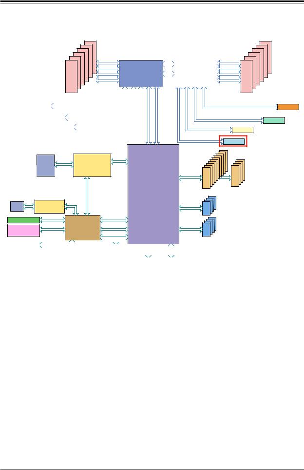
Figure 1-5. Intel C622 Chipset: System Block Diagram
Note: This is a general block diagram and may not exactly represent the features on your motherboard. See the System Specifications appendix for the actual specifications of your motherboard.
15

SuperStorageServer SSG-6019P-ACR12L User's Manual
Chapter 2
Server Installation
2.1 Overview
This chapter provides advice and instructions for mounting your system in a server rack. If your system is not already fully integrated with processors, system memory etc., refer to
Chapter 4 for details on installing those specific components.
Caution: Electrostatic Discharge (ESD) can damage electronic components. To prevent such damage to PCBs (printed circuit boards), it is important to use a g
1ounded wrist strap, handle all PCBs by their edges and keep them in anti-static bags when not in use.
2.2 Preparing for Setup
The box in which the system was shipped should include the rackmount hardware needed to install it into the rack. Please read this section in its entirety before you begin the installation.
Choosing a Setup Location
•The system should be situated in a clean, dust-free area that is well ventilated. Avoid areas where heat, electrical noise and electromagnetic fields are generated.
•Leave enough clearance in front of the rack so that you can open the front door completely (~25 inches) and approximately 30 inches of clearance in the back of the rack to allow sufficient space for airflow and access when servicing.
•This product should be installed only in a Restricted Access Location (dedicated equipment rooms, service closets, etc.).
•This product is not suitable for use with visual display workplace devices according to §2 of the German Ordinance for Work with Visual Display Units.
16

Chapter 2: Server Installation
Rack Precautions
•Ensure that the leveling jacks on the bottom of the rack are extended to the floor so that the full weight of the rack rests on them.
•In single rack installations, stabilizers should be attached to the rack. In multiple rack installations, the racks should be coupled together.
•Always make sure the rack is stable before extending a server or other component from the rack.
•You should extend only one server or component at a time - extending two or more simultaneously may cause the rack to become unstable.
Server Precautions
•Review the electrical and general safety precautions in Appendix B.
•Determine the placement of each component in the rack before you install the rails.
•Install the heaviest server components at the bottom of the rack first and then work your way up.
•Use a regulating uninterruptible power supply (UPS) to protect the server from power surges and voltage spikes and to keep your system operating in case of a power failure.
•Allow any drives and power supply modules to cool before touching them.
•When not servicing, always keep the front door of the rack and all covers/panels on the servers closed to maintain proper cooling.
Rack Mounting Considerations
Ambient Operating Temperature
If installed in a closed or multi-unit rack assembly, the ambient operating temperature of the rack environment may be greater than the room's ambient temperature. Therefore, consideration should be given to installing the equipment in an environment compatible with the manufacturer’s maximum rated ambient temperature (TMRA).
Airflow
Equipment should be mounted into a rack so that the amount of airflow required for safe operation is not compromised.
17
SuperStorageServer SSG-6019P-ACR12L User's Manual
Mechanical Loading
Equipment should be mounted into a rack so that a hazardous condition does not arise due to uneven mechanical loading.
Circuit Overloading
Consideration should be given to the connection of the equipment to the power supply circuitry and the effect that any possible overloading of circuits might have on overcurrent protection and power supply wiring. Appropriate consideration of equipment nameplate ratings should be used when addressing this concern.
Reliable Ground
A reliable ground must be maintained at all times. To ensure this, the rack itself should be grounded. Particular attention should be given to power supply connections other than the direct connections to the branch circuit (i.e. the use of power strips, etc.).
To prevent bodily injury when mounting or servicing this unit in a rack, you must take special precautions to ensure that the system remains stable. The following guidelines are provided to ensure your safety:
•This unit should be mounted at the bottom of the rack if it is the only unit in the rack.
•When mounting this unit in a partially filled rack, load the rack from the bottom to the top with the heaviest component at the bottom of the rack.
•If the rack is provided with stabilizing devices, install the stabilizers before mounting or servicing the unit in the rack.
18
Chapter 2: Server Installation
2.3 Installing the Chassis
This section provides information on installing the chassis into a rack unit with the rails provided.
The Toolless Rail System
The SC802 chassis uses a toolless rail system that does not need -- as the name implies -- any hand tool to mount the rails and chassis into the server rack. The toolless rail system has locking mechanisms on each end of the rails that latch and lock onto the square mounting holes which are located on the front and back of the server rack. When these rails are secure, the chassis' left and right sides will simply rest on the inner rail 'lip' of these rails, which can be freely pulled out or pushed in as needed. The chassis is then secured to the rack by two thumb screws.
Mounting Ends
Inner Rail Lip
Left Rail
Mounting Ends
Right Rail
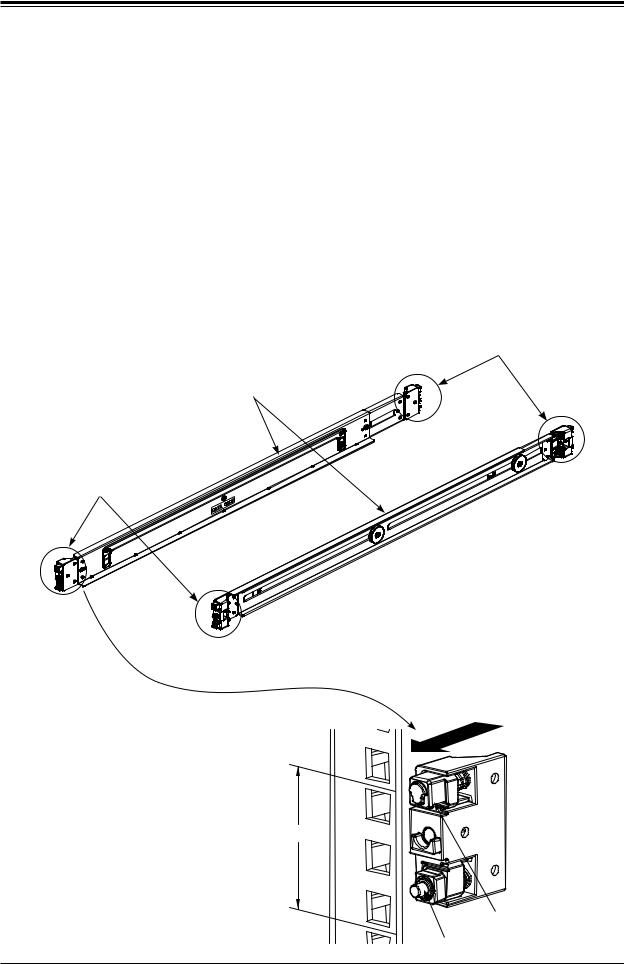
Figure 2-1. Toolless Rails
Insert the mounting ends of the rails into |
Rack Post |
the square mounting holes in 1U space |
|
on the rack post |
|
1U Space
Mounting End
Top Hook
Bottom Lock
19
SuperStorageServer SSG-6019P-ACR12L User's Manual
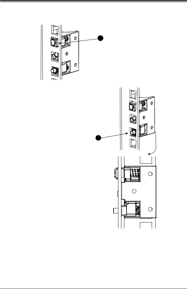
1A Insert the top hook first, push it downwards to allow its hook to rest and engage the selected mounting hole.
When the top hook is rested and engaged into place, push the bottom lock into the lower hole until it clicks and snaps into place
Insert until bottom lock snaps into place. This push button will pop out to indicate it is locked.
This illustration shows a sideways view of one properly mounted rail.
1 |
B |
Top hook |
Bottom lock |
Figure 2-2. Installing the Outer Rails to the Rack
20
Chapter 2: Server Installation
 Slide rail mounted equipment is not to be used as a shelf or a work space.
The illustration below shows both the left and right rails mounted on a rack, ready to accept the server chassis.
Right Rail
Left Rail
Figure 2-3. Installing the Toolless Rails to the Rack
Note: The figure above is for illustrative purposes only. Always install servers at the bottom of the rack first.
Warning: Stability hazard. The rack stabilizing mechanism must be in place, or the rack must be bolted to the floor before you slide the unit out for servicing. Failure to stabilize the rack can cause the rack to tip over.
21
SuperStorageServer SSG-6019P-ACR12L User's Manual
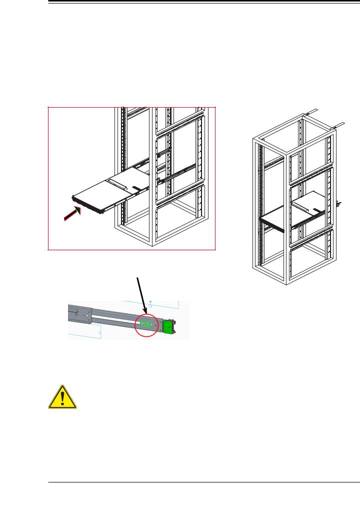
Sliding the Chassis onto the Rack Rails
Installing the Chassis into a Rack
1.Align the chassis rails with the front of the rack rails.
2.Slide the chassis rails into the rack rails, letting it rest on to the inner rail lips, while keeping the pressure even on both sides. The spring latch engages when the chassis is part way in. Push the server completely into the rack.
The rails will have pre-installed stop pins that are intended as a safety stop for longer rail applications. Remove these if necessary.
Figure 2-4. Installing the Server into a Rack
Note: The figure above is for illustrative purposes only. Always install servers at the bottom of the rack first.
Warning: do not pick up the server with the front handles. They are designed to pull the system from a rack only.
22
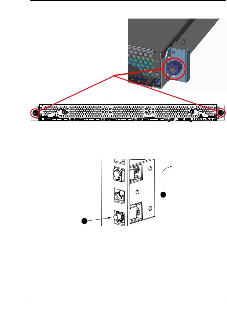
Chapter 2: Server Installation
The chassis can then be secured to the rack by two thumb screws located on the left and right of the front side of the chassis.
Figure 2-5. Securing the Chassis to the Rack
Removing the Rails
Removing a rail is basically just the reverse of the installation procedure.
Pull up and away from the rack
B1
Push bottom
lock button
1A
Figure 2-6. Removing a Rail
23

SuperStorageServer SSG-6019P-ACR12L User's Manual
Chapter 3
Maintenance and Component Installation
This chapter provides instructions on installing and replacing main system components. To prevent compatibility issues, only use components that match the specifications and/or part numbers given.
Installation or replacement of most components require that power first be removed from the system. Please follow the procedures given in each section.
3.1 Removing Power
Use the following procedure to ensure that power has been removed from the system. This step is necessary when removing or installing non hot-swap components or when replacing a non-redundant power supply.
1.Use the operating system to power down the system.
2.After the system has completely shut-down, disconnect the AC power cord(s) from the power strip or outlet. (If your system has more than one power supply, remove the AC power cords from all power supply modules.)
3.Disconnect the power cord(s) from the power supply module(s).
24
Chapter 3: Maintenance and Component Installation
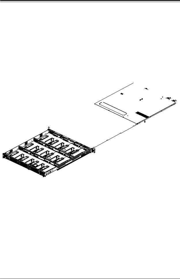
3.2 Accessing the System
The system is fully accessible by loosening the two front thumbscrews and pulling out the drive drawer completely.
Lever |
Loosen Thumbscrews |
Lever |
|
then pull out levers |
|
Pull Out
Figure 3-1. Removing the Chassis Cover
Removing a Chassis Cover
1.Loosen the two thumb screws on the front of the chassis to unlock the levers on both sides. Rotate counter clockwise to unlock, clockwise to lock.
2.Pull out the two levers at the same time. This is will pop out the internal drive drawer, partially exposing the drive trays.
3.Pull the drive drawer out until it stops.
Caution: Except for short periods of time, do not operate the system without the cover in place. The chassis cover must be in place to allow proper airflow and to prevent overheating.
25
SuperStorageServer SSG-6019P-ACR12L User's Manual
3.3 Motherboard Components
Processor and Heatsink Installation
The Intel Xeon 8100/6100/5100/4100/3100 processor series comes in two models: Fabric (F model) and Non-Fabric (Non-F model). Only the Non-Fabric model is supported for this system.
The processor (CPU) and heatsink should be assembled together first to form the processor heatsink module (PHM), and then install the PHM into the CPU socket.
Caution: Use ESD protection. Do not touch the underside of the CPU. Improper installation or socket misalignment can cause serious damage to the CPU or socket which may require manufacturer repairs.
Notes:
•All power should be off, as described in Section 3.1, before installing the processors.
•When handling the processor package, avoid placing direct pressure on the label area of the CPU or socket.
•Check that the plastic socket dust cover is in place and none of the socket pins are bent— otherwise, contact your retailer.
•Refer to the Supermicro website for updates on CPU support.
•Graphics in this manual are for illustration. Your components may look slightly different.
The Xeon Scalable Processor
Non-F model Processor
Figure 3-2. Xeon Scalable Processors
26
Chapter 3: Maintenance and Component Installation
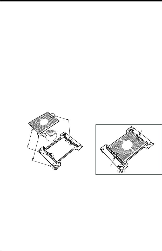
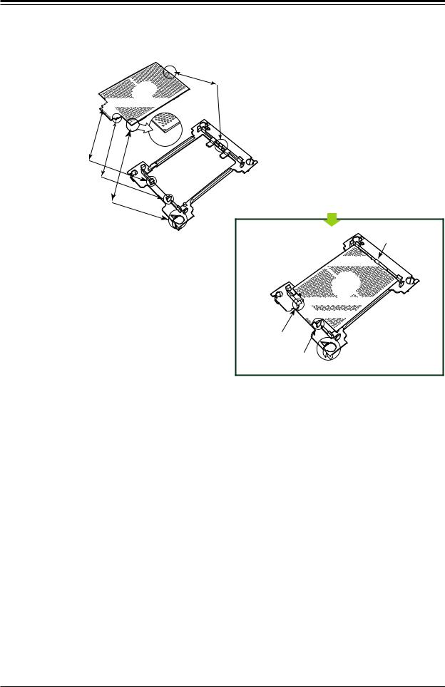
Assembling the Processor Package
Attach the processor to the thin processor clip to create the processor package.
1.On the top corner of the CPU, locate pin 1 (A), marked by a triangle. Also, locate notch B and notch C (and notch D for F models) on the CPU as shown below.
2.On the top of the processor clip, locate the corner marked by a hollow triangle as the position for pin 1. Also locate notch B and notch C (and D for F models) on the processor clip.
3.Align pin 1 of the CPU with its proper position on the processor clip and carefully insert the CPU into the processor clip. Slide notch B of the CPU into tab B of the processor clip, and slide notch C of the CPU into tab C of the processor clip (and D for F models) until the processor clip tabs snap onto the CPU.
4.Examine all corners to ensure that the CPU is properly seated and secure on the processor clip.
The processor package assembly is created.
CPU (Upside Down) w/CPU LGA Lands up
C
Align Notch C of the CPU
and Notch C of the Processor Clip
B |
|
|
Allow Notch C to |
|
|
|
latch on to CPU |
A |
|
|
C |
Pin 1 |
C |
|
|
|
|
|
|
Align Notch B of the CPU |
|
|
|
and Notch B of the Processor Clip |
|
|
|
B |
CPU/Heatsink Package |
B |
|
|
|
||
(Upside Down) |
|
|
|
Align CPU Pin 1 |
|
|
|
A |
|
Allow Notch B to |
|
|
latch on to CPU |
A |
|
|
|
|
Processor Package Assembly for the non-F Model Processors
(with CPU mounted on the Processor Clip)
27
SuperStorageServer SSG-6019P-ACR12L User's Manual
CPU (Upside Down) |
D |
w/CPU LGA Lands up |
|
C


Align Notch D of the CPU
and Notch D of the Processor Clip
B |
A |
|
|
Align Notch C of the CPU |
Pin 1 |
D |
|
and Notch C of the Processor Clip |
|
|
|
Align Notch B of the CPU |
|
C |
|
and Notch B of the Processor Clip |
|
|
|
|
|
B |
CPU/Heatsink Package |
|
|
(Upside Down) |
|
|
|
|
|
Align CPU Pin 1 |
|
|
|
A
Allow Notch D to
latch on to CPU


 D
D
C


 B
B


Allow Notch C to latch on to CPU
Allow Notch B to 


 A latch on to CPU
Processor Package Assembly for the -F Model Processors
(with CPU mounted on the Processor Clip)
28
Chapter 3: Maintenance and Component Installation
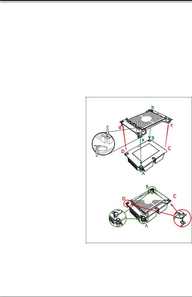
After creating the processor package assembly, mount it onto the heatsink to create the processor heatsink module (PHM).
1.On the heatsink label, locate "1" and the corner next to it. Turn the heatsink upside down with the thermal grease side facing up, keeping track of the "1" corner.
2.Remove the protective thermal film if present. If this is a new heatsink, the necessary thermal grease has been pre-applied in the factory. If the heatsink is not new, apply the proper amount of the thermal grease.
3.In the plastic processor clip, locate the hollow triangle at the corner ("a" in the drawing below) next to a hole and plastic mounting clips. There is a similar hole and mounting clips at the diagonal corner of the of the processor clip ("b" in the drawing).
4.With the underside of heatsink and the underside of the processor package facing up, align the "1" corner on the heatsink ("A" in the drawing) against the mounting clips next to the hollow triangle ("a") on the processor package.
5.Also align the corner ("B") at the diagonal side of the heatsink with the corresponding clips on the processor package ("b").
6.Once aligned, press the processor package assembly onto the heatsink until the mounting clips (at a, b, c, and d) snap into place.
The processor heatsink module is assembled.
Non-Fabric CPU and Processor Clip
(Upside Down) |
b |
|
Triangle on the CPU |
d |
|
c |
|
|
|
|
|
|
a |
B |
|
|
|
D


 C
C
Triangle on the
Processor Clip
Heatsink |
A |
(Upside Down) |
On Locations of (C, D), the notches
B |
snap onto the heat sink’s |
mounting holes |
D 


 C
C
A
On Locations (A, B), the notches |
|
|
Make sure Mounting |
||
snap onto the heatsink’s sides |
||
Notches snap into place |
||
|
||
|
|
Assembling the Processor Heatsink Module
29
SuperStorageServer SSG-6019P-ACR12L User's Manual
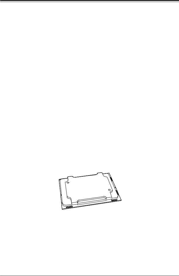
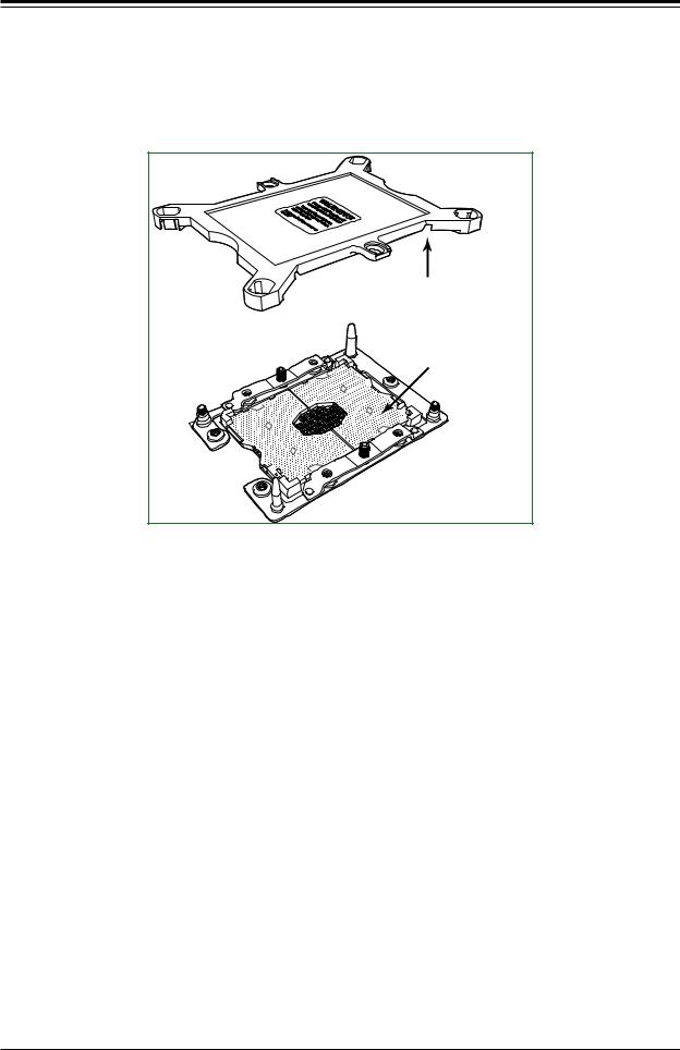
Removing the Dust Cover from the CPU Socket
Remove the dust cover from the CPU socket, exposing the socket pins as shown below. Caution: Do not touch the socket pins.
Dust Cover |
Remove the dust cover from |
the CPU socket. Do not |
touch the socket pins! |
Socket Pins |
CPU Socket |
Removing the Socket Dust Cover
30
Loading...