


USB AUDIO INTERFACE
EN
DE
FR
ES
I T
JA

Contents
Introduction............................................................ |
3 |
Contents in this Operation Manual............................... |
3 |
Features ....................................................................... |
3 |
Panel Controls and Terminals (Details)............... |
5 |
Rear Panel.................................................................... |
5 |
Front Panel ................................................................... |
6 |
Panel Controls for the Software Programs ......... |
8 |
Introduction .................................................................. |
8 |
Control Panel of the Audio Driver................................. |
8 |
dspMixFx UR824.......................................................... |
9 |
Dedicated Windows for Cubase Series ..................... |
15 |
Sweet Spot Morphing Channel Strip (Channel Strip). 20 |
|
REV-X ......................................................................... |
22 |
Guitar Amp Classics .................................................. |
24 |
Usage Examples .................................................. |
26 |
Introduction ................................................................ |
26 |
Recording with the Channel Strip and REV-X............ |
26 |
Connecting the Mic Preamp ...................................... |
28 |
Using the Device Without a Computer....................... |
28 |
Using the Device with an iPad ................................... |
29 |
Appendix .............................................................. |
31 |
Glossary ..................................................................... |
31 |
Contents of the Getting Started Section .................... |
32 |
Signal Flow................................................................. |
33 |
Block Diagrams.......................................................... |
35 |
UR824 Operation Manual 2

Introduction
Contents in this Operation Manual
This Operation Manual explains how to use the device. The explanations in this manual assume that you’ve set up the device and prepared it for use according to the Getting Started document. If you haven’t done that yet, refer to the Getting Started document and complete the setup before reading this manual.
Features
High-resolution Microphone
Preamplifiers (D-PRE)
Discrete microphone preamps featuring a highperformance inverted Darlington circuit configuration achieve low distortion and noise while delivering sound with eminently musical balance and character.
Supports a Variety of Inputs
Switchable phantom power is provided for condenser microphones, electric guitars and basses can be directly connected via a HI-Z (high impedance) input, and a PAD is provided for input matching with high-level signals from electronic instruments. Optical input connectors enable direct digital input in ADAT or S/PDIF format from a variety of digital audio devices, while a BNC-connector for word clock input and output allows precise synchronization with other digital equipment.
Powerful DSP Mixer (dspMixFx)
A DSP mixer that can mix up to 24 input channels to four stereo outputs is built in. Two of those stereo mixes can be independently assigned to separate headphone outputs. It is also possible to directly route a stereo input to any specified stereo output. A number of DSP effects that can be applied to input signals are also provided, and since it is a hardware mix with there is no monitoring latency.
Introduction
DSP Effect: Sweet Spot Morphing
Channel Strip
The Sweet Spot Morphing Channel Strip (“Channel Strip” for short) is a multi-effect that combines compression and EQ. Advanced sound engineering know-how is condensed into a number of presets that can simply be recalled as required for professional results. Up to eight channel strips can be used at a time, and it can be assigned either to the monitor sound only, or to both the monitor and recorded sound.
DSP Effect: REV-X Reverb
REV-X is a digital reverb platform developed by Yamaha for pro audio applications. One REV-X effect is included in this unit. Input signals can be sent to the REV-X effect, and the REV-X effect is applied only to the monitor outputs.
DSP Effect: Guitar Amp Classics
Guitar Amp Classics are guitar amp effects that make extensive use of advanced Yamaha modeling technology. One Guitar Amp Classics effect can be used at a time, and it can be assigned either to the monitor sound only, or to both the monitor and recorded sound.
The maximum number of Channel Strip and Guitar Amp Classics iterations which can be used simultaneously has restrictions. Refer to the “Limitations on the use of effects” (page 34).
DSP Effect VST Plug-ins Included
VST3 Plug-ins (page 31) of the Channel Strip, REV-X and Guitar Amp Classics effects are included for use with Cubase series or similar VST-compatible DAW software.
Free Download of Cubase AI
Steinberg’s Cubase AI digital audio workstation (DAW, page 31) is available free for downloading via our website, specifically for customers who have purchased the UR824. Cubase AI is the entry-level version of the Cubase series DAW products, providing the basic functionality you need for music production and editing.
UR824 Operation Manual 3
Introduction
Class Compliant mode
In Class Compliant mode, the UR824 works with the iPad through the Apple iPad Camera Connection Kit. It can be used with iOS compatible music production applications such as Steinberg Cubasis for convenient high-quality recording anywhere, at any time. A computer can also be used in CC mode.
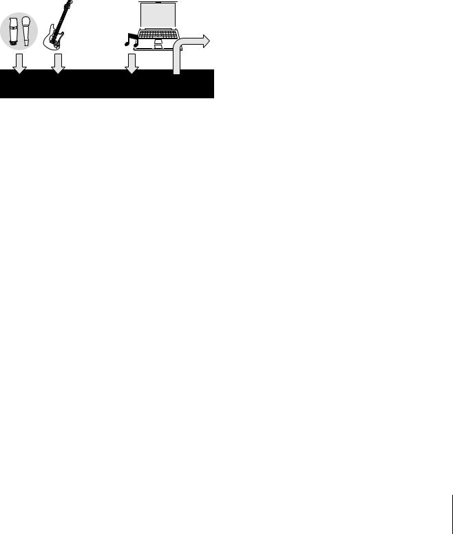
Loopback function
Loopback function facilitates video delivery and other Internet related activities. This function mixes the input audio signals (LINE, Guitar, Mic, etc) and the audio signals playing back in the software into two channels in the UR824, and back to the computer for live broadcasting via the Internet.
BGM  Delivery
UR824 DSP Mixer
UR824 Operation Manual 4
Panel Controls and Terminals (Details)
Panel Controls and
Terminals (Details)
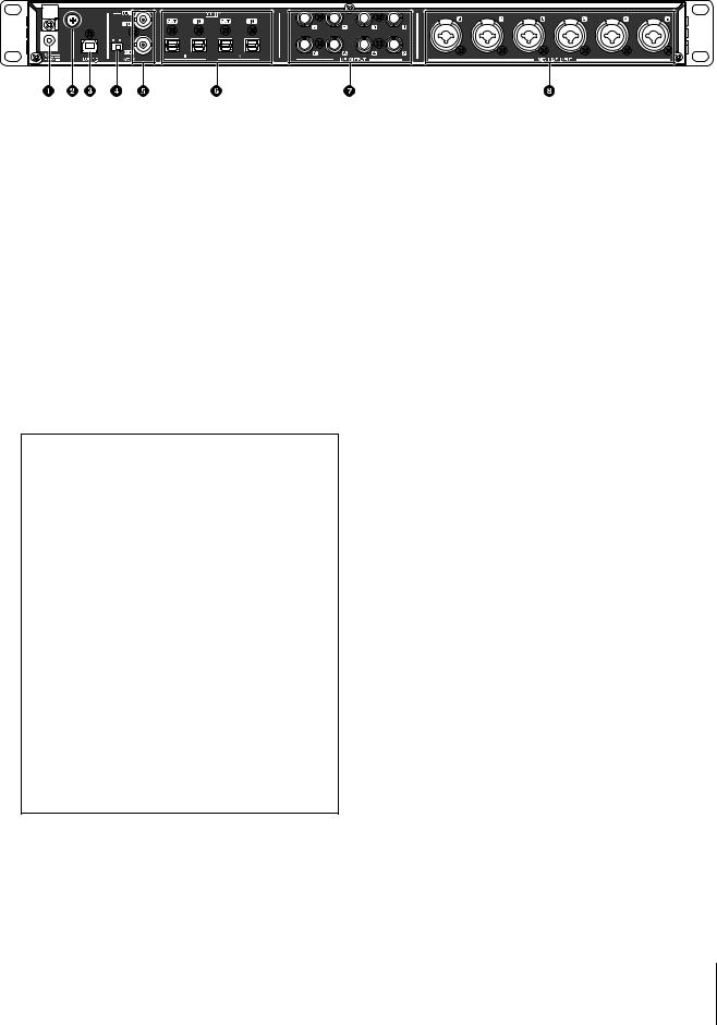
Rear Panel
1DC IN 16V
For connection to the AC power adaptor.
2Grounding screw
For connection to a ground wire.
If you have a problem with hum or noise, use this terminal to connect to ground. The noise may be reduced.
3USB2.0 (USB port)
For connection to a computer or iPad. Apple iPad Camera Connection Kit or Lightning to USB Camera Adapter are required when connecting the UR824 with an iPad.
USB Port Precautions
NOTICE
Be sure to observe the following points when connecting to the computer’s USB interface. Failing to do so may result in the computer freezing or shutting down, as well as corruption or even loss of data. If the device or computer does freeze, restart the application or computer.
•Be sure to wake the computer from sleep/ suspended/stand by mode before making a connection to the computer’s USB port.
•Before turning on the power to the device, connect the computer to the USB port.
•Before turning on/off the device or plugging/ unplugging the USB cable, quit any open application software on the computer.
•When connecting or disconnecting the USB cable, be sure to set all output level controls to the minimum.
•Wait at least six seconds between connecting or disconnecting the USB cable.
4WCLK switch
Switches between IN and OUT for the upper WCLK terminal.
5WCLK IN (OUT)/OUT (BNC connector)
For connection to the device which transmits and receives the word clock.
6OPTICAL A/B IN/OUT (optical)
For connection to a digital audio device.
You can select the format of the OPTICAL A/B between ADAT and S/PDIF. To select the format, use the “Setup Window” (page 13) in the section “dspMixFx UR824” or the “Settings Window” (page 19) in the section “Dedicated Windows for Cubase Series.”
You can select the output signal of the OPTICAL A/B OUT. To select the output signal, use the “Setup Window” (page 13) in the section “dspMixFx UR824” or the “Output Routing Window” (page 18) in the section “Dedicated Windows for Cubase Series.”
7LINE OUTPUT 1–8 (phone type, balanced/unbalanced)
For connection to monitor speakers. When the monitor speakers have a balanced input, connect them with a balanced cable.
You can select the output signal of LINE OUTPUT 1–8. To select the output signal, use the “Setup Window” (page 13) in the section “dspMixFx UR824” or the “Output Routing Window” (page 18) in the section “Dedicated Windows for Cubase Series.”
8MIC/LINE INPUT 3–8 (XLR/phone type, balanced/unbalanced)
For connection to a microphone or digital instrument.
UR824 Operation Manual 5
Panel Controls and Terminals (Details)
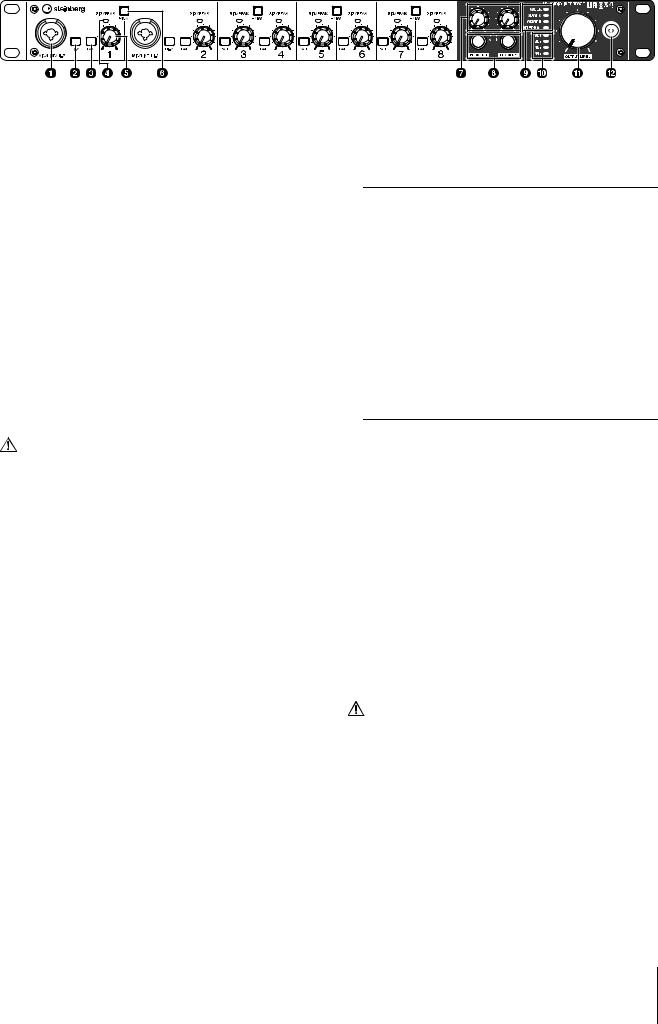
Front Panel
1MIC/LINE/HI-Z (XLR/phone type, balanced/unbalanced)
For connection to a microphone, digital instrument, electric guitar, or electric bass.
2HI-Z switch
Turns on (O) and off (N) the HI-Z of the MIC/ LINE/HI-Z.
Turn this switch on when connecting high impedance instruments, such as an electric guitar or electric bass, directly to the MIC/LINE/ HI-Z.
When you turn this switch on, use an unbalanced phone type cable for connection between the instrument and the MIC/LINE/HI-Z. If you use a balanced cable or an XLR cable, this device will not work correctly.
CAUTION
•Do not connect or disconnect a device while turning on the HI-Z switch. Doing so can damage the connected device and/or the unit itself.
•To protect your speaker system, leave the monitor speakers turned off when turning the HI-Z switch on/ off. It’s also a good idea to turn all output volume controls down to their minimum. Neglect of these precautions may result in large noise bursts that may damage your equipment, your ears, or both.
3PAD switch
Turns on (O) and off (N) the PAD of the analog input jacks (MIC/LINE/HI-Z and MIC/LINE INPUT).
When you turn this switch on, the input signal level of the analog input jacks will be attenuated by 26 dB. Turn this switch on when connecting high output equipment, such as a synthesizer, to the analog input jacks.
4SIG/PEAK lamp
Indicates the input signal level of the analog input jacks (MIC/LINE/HI-Z and MIC/LINE INPUT).
Lamp status |
Description |
Red |
-3 dB or more |
Green |
40 dB or more – less than -3 dB |
Dark |
Less than -40 dB |
|
|
5INPUT GAIN knob
Adjusts the input signal level of the analog input jacks (MIC/LINE/HI-Z and MIC/LINE INPUT). The adjustable range varies depending on the on/off setting of the PAD switch.
PAD |
Range |
On |
-34 dB – +10 dB |
Off |
-60 dB – -16 dB |
|
|
6+48V button
Turns on (lit) and off (dark) the phantom power of XLR type connections on analog input jacks (MIC/LINE/HI-Z and MIC/LINE INPUT).
When you turn on this button, phantom power will be supplied to the two adjacent analog input jacks. Turn on this button when connecting phantom powered devices, such as a condenser microphone, to the analog input jacks.
CAUTION
•Make sure that phantom power is turned OFF unless it is needed.
•When turning phantom power ON, make sure that no equipment other than phantom-powered devices such as condenser microphones are connected. Devices other than condenser microphones may be damaged if connected to the phantom power supply. Note, however, that the switch may be left on when connecting to balanced dynamic microphones. When connecting an unbalanced device to the MIC/LINE/HI- Z and MIC/LINE INPUT and phantom power is turned on, hum or noise may result; this is not a malfunction or failure in the device.
UR824 Operation Manual 6

•Do not connect or disconnect a device while phantom power is applied. Doing so can damage the connected device and/or the unit itself.
•To protect your speaker system, leave the monitor speakers turned off when switching the phantom power on/off. It’s also a good idea to turn all output volume controls down to their minimum. Neglect of these precautions may result in large noise bursts that may damage your equipment, your ears, or both.
7PHONES knob 1/2
Adjusts the output signal level of PHONES 1/2. This output signal level is not affected by the OUTPUT LEVEL knob.
PHONES 1/2 output one of the MIX 1–4 signals. To select the output signal, use the “Headphone Area” (page 13) in the section “dspMixFx UR824” or the “Headphones Window” (page 18) in the section “Dedicated Windows for Cubase Series.”
8PHONES 1/2 (phone type, stereo)
For connection to a set of headphones.
PHONES 1/2 output one of the MIX 1–4 signals. To select the output signal, use the “Headphone Area” (page 13) in the section “dspMixFx UR824” or the “Headphones Window” (page 18) in the section “Dedicated Windows for Cubase Series.”
9Word clock source lamp
Indicates the word clock (page 31) source of the device.
Lamp |
Clock Source |
WCLK |
The word clock signal input to the |
|
WCLK IN. |
ADAT A |
The word clock signal input to the |
|
OPTICAL A IN. |
ADAT B |
The word clock signal input to the |
|
OPTICAL B IN. |
INTERNAL |
The internal word clock signal. |
|
|
Lamp status |
Description |
Lit |
Synchronized with the clock |
|
source. |
Flash |
Not synchronized with the clock |
|
source. |
|
|
To select the clock source of the device, use the “(device name) Window” (page 8) in the section “Control Panel of the Audio Driver” in Windows or Audio MIDI Setup in Mac.
Panel Controls and Terminals (Details)
)Sample rate lamp
Indicates the sample rate of the device.
Lamp |
Sample Rate |
96k and 48k |
192 kHz |
88k and 44k |
176.4 kHz |
96k |
96 kHz |
88k |
88.2 kHz |
48k |
48 kHz |
44k |
44.1 kHz |
|
|
To select the sample rate of the device, use the “(device name) Window” (page 8) in the section “Control Panel of the Audio Driver” in Windows or Audio MIDI Setup in Mac.
!OUTPUT LEVEL knob
Adjusts the output level of the LINE OUTPUT 1–8 signals.
To select the LINE OUTPUT for adjusting the output signal level, use the “Setup Window” (page 13) in the section “dspMixFx UR824” or the “Master Levels Window” (page 19) in the section “Dedicated Windows for Cubase Series.”
@Power button
Turn the power on and off.
Power on Press the power button (  ). The power button will light.
Power off Hold down the power button (  ) for over two seconds. The power button will light dimly.
UR824 Operation Manual 7
Panel Controls for the Software Programs
Introduction
This section explains software operations for using the UR824 with a computer.
NOTE
The software programs below do not apply to iPad.
Control Panel of the Audio
Driver
This is the control panel for selecting the general settings of the audio driver. Click the upper tabs to select the desired window.
Screenshot
How to Open the Window
Windows
•[Control Panel] [Hardware and Sound] or [Sounds, Speech, and Audio Devices] [Yamaha Steinberg USB Driver]
•From the Cubase series menu, [Devices] [Device Setup] [Yamaha Steinberg USB ASIO] [Control Panel]
Mac
•[System Preferences] [Yamaha Steinberg USB]
•From the Cubase series menu, [Devices] [Device Setup] [Steinberg UR824] [Control Panel] [Open Config App]
Panel Controls for the Software Programs
Panel Controls
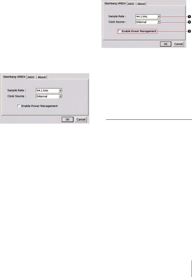
(Device name) Window
This is the window for selecting the sample rate or word clock source of the device.
1Sample Rate (Windows only)
Selects the sample rate of the device.
Option: 44.1 kHz, 48 kHz, 88.2 kHz, 96 kHz, 176.4 kHz, 192 kHz
NOTE
For Mac, select the sample rate of the device via the Audio MIDI Setup.
2Clock Source (Windows only)
Selects the word clock source of the device.
Option |
Clock Source |
WCLK |
The word clock signal input to the |
|
WCLK IN. |
ADAT A |
The word clock signal input to the |
|
OPTICAL A IN. |
ADAT B |
The word clock signal input to the |
|
OPTICAL B IN. |
Internal |
The internal word clock signal. |
|
|
NOTE
For Mac, select the word clock source of the device via the Audio MIDI Setup.
UR824 Operation Manual 8
3Enable Power Management
Select enable (checkmark) and disable (no checkmark) for automatic power off.
The device is equipped with an automatic power off function. When this function is enabled, the power of the device will turn off automatically (after thirty minutes) when one of the following actions is performed. The power button will flash during the thirty-minute interval.
•Turning off the computer.
•Disconnecting the USB cable between the device and the computer.
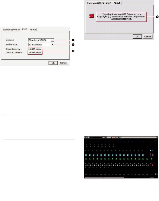
ASIO Window (Windows only)
This is the window for selecting the ASIO driver settings.
1Device
Selects the device that will be using the ASIO driver. This function is available when connecting to the computer two or more devices compatible with the Yamaha Steinberg USB Driver.
2Buffer Size
Selects the buffer size (page 31) for the ASIO driver. The range varies depending on the sample rate.
Sample Rate |
Range |
44.1 kHz/44.8 kHz |
64 samples – 2048 samples |
88.2 kHz/96 kHz |
128 samples – 4096 samples |
176.4 kHz/192 kHz 256 Samples – 8192 Samples
NOTE
For Mac, select the buffer size in the buffer size selecting window, which is opened from an application such as DAW software.
Panel Controls for the Software Programs
3Input Latency/Output Latency
Indicates the delay time for the audio input and output in millisecond units.
Audio latency varies depending on the value of the ASIO buffer size. The lower the value of the ASIO buffer size, the lower the value of Audio latency.
About Window
This window indicates information about the audio driver.
1About
Indicates the version and copyright of the audio driver. The letters “x.x.x” indicate the version number.
dspMixFx UR824
This is the window for configuring the DSP mixer and DSP effect equipped with the device. The signals flow top-to-down and left-to-right. The dspMixFx UR824 provides stand-alone operation.
NOTE
You cannot operate the dspMixFx UR824 while a Cubase series DAW is running. When Cubase is running, configure the DSP mixer and DSP effect from “Dedicated Windows for Cubase Series” (page 15).
Screenshot
UR824 Operation Manual 9
How to Open the Window
Windows
[All Programs] or [All apps] [Steinberg UR824] [dspMixFx UR824]
Mac
[Applications] [dspMixFx UR824]
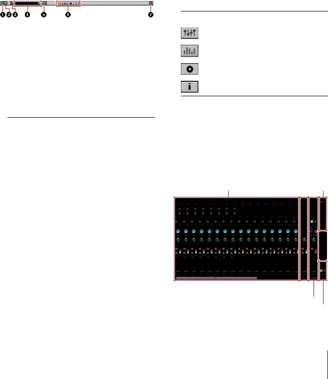
Panel Controls
Tool Area
This is the area for configuring the common settings of the dspMixFx UR824.
1Quit
Quits the dspMixFx UR824.
2Minimize
Minimizes the dspMixFx UR824 window.
3Menu
Provides four menus, including Save the settings file of the dspMixFx UR824 (page 31) and Import Scene (page 31).
Menu |
Description |
Open |
Opens the settings file of the |
|
dspMixFx UR824. |
Save |
Saves the settings file of the |
|
dspMixFx UR824 to a computer. |
Import |
Imports a scene from the settings file |
Scene |
of the dspMixFx UR824. Select the |
|
settings file of the dspMixFx UR824 |
|
and import scene on the left side of |
|
the IMPORT SCENE window. Select |
|
the destination for importing on the |
|
right side of the window. Click [OK] |
|
to import it. |
Initialize All |
Deletes all the saved scenes. |
Scenes |
|
|
|
Panel Controls for the Software Programs
4Scene
Indicates the scene name. You can change the scene name by clicking on it.
When you click the button on the right side, the window for calling up the scene will open. You can call up the scene by clicking it. To cancel calling up the scene, click outside of the window.
5STORE
Opens the scene store window. Enter the desired scene name into the STORE NAME field. Select the destination for storing the scene in the No. NAME field. Click [OK] to store the scene.
6Selecting the window
Selects the dspMixFx UR824 window. The selected window icon will light in red.
Icon Description
Main window (page 10)
Level Meter window (page 13)
Setup window (page 13)
Information window (page 15)
7Help
Opens the Operation Manual (this manual).
Main Window
This is the window for configuring the entire signal flow.
Channel Area (page 11) MIX Area (page 13)
DAW Area (page 12) 
Master Area (page 12) 
Headphone Area (page 13) 
UR824 Operation Manual 10
Channel Area
This is the area for configuring the input channel settings.
1Channel Link
Turns on (lit) and off (dark) the channel link of two adjacent channels. When you turn this on, two mono channels will become one stereo channel.
2Level Meter
Indicates the signal level.
3High Pass Filter
Turns on (lit) and off (dark) the high pass filter.
To select the cutoff frequency of the high pass filter, use the “Setup Window” (page 13) in the section “dspMixFx UR824.”
4Phase
Turns on (lit) and off (dark) the phase inversion of the signal.
Panel Controls for the Software Programs
5Effect Insertion Location
Selects the insertion location of an effect.
Option |
Description |
MON.FX |
Applies an effect to only the monitor |
|
signal (sent to the device). |
INS.FX |
Applies an effect to both the monitor |
|
signal (sent to the device) and the |
|
recording signal (sent to the DAW |
|
software). |
|
|
6Effect On/Off
Turns the effect on (lit) and off (dark).
7Effect Edit
Opens (lit) and closes (dark) the selected effect setup window.
8Effect Type
Selects the effect.The maximum number of Channel Strip and Guitar Amp Classics iterations which can be used simultaneously has restrictions. Refer to the “Limitations on the use of effects” (page 34).
9REV-X Send
Adjusts the signal level which is sent to the REV-X.
Range: -∞ dB – +6.00 dB
)Pan
Adjusts the pan.
Range: L16 – C – R16
!Mute
Turns the mute on (lit) and off (dark).
@Solo
Turns the solo on (lit) and off (dark).
#+48V
Indicates the on/off status of the phantom power function of the device.
$Fader
Adjusts the signal level.
Range: -∞ dB – +6.00 dB
UR824 Operation Manual 11
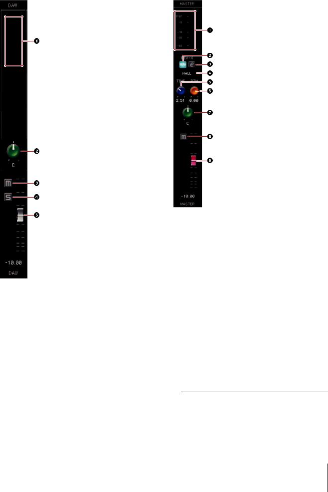
DAW Area
This is the area for configuring the DAW channel settings.
1Level Meter
Indicates the signal level.
2Pan
Adjusts the pan.
Range: L16 – C – R16
3Mute
Turns the mute on (lit) and off (dark).
4Solo
Turns the solo on (lit) and off (dark).
5Fader
Adjusts the signal level.
Range: -∞ dB – +6.00 dB
Panel Controls for the Software Programs
Master Area
This is the area for configuring the master channel settings.
1Level Meter
Indicates the signal level.
2REV-X Send On/Off
Turns the REV-X on (lit) and off (dark).
You can turn this on for one of MIX 1–4.
3REV-X Edit
Opens (lit) and closes (dark) the “REV-X” (page 22) setup window.
4REV-X Type
Selects the REV-X type.
Option: Hall, Room, Plate
5REV-X Time
Adjusts the reverb time of the REV-X. This parameter links to Room Size. The adjustable range varies depending on the REV-X type.
REV-X type |
Range |
Hall |
0.103 sec – 31.0 sec |
Room |
0.152 sec – 45.3 sec |
Plate |
0.176 sec – 52.0 sec |
|
|
UR824 Operation Manual 12
 Loading...