


 Loading...
USB AUDIO INTERFACE
EN Operation Manual

Contents |
|
Main Features ........................................... |
2 |
Panel Controls and Terminals ................ |
3 |
Front Panel .......................................................... |
3 |
Rear Panel ........................................................... |
5 |
Software .................................................... |
6 |
Yamaha Steinberg USB Driver ............................ |
6 |
dspMixFx UR-C.................................................... |
8 |
Dedicated Windows for Cubase Series ............. |
13 |
Sweet Spot Morphing Channel Strip.................. |
16 |
REV-X ................................................................ |
18 |
Guitar Amp Classics .......................................... |
20 |
Using with a Computer .......................... |
23 |
Connection Example.......................................... |
23 |
Configuring Audio Driver Settings on the DAW |
|
Software............................................................. |
24 |
Recording/Playback ........................................... |
25 |
Using with an iOS Device ...................... |
27 |
Connection Example.......................................... |
27 |
Recording/Playback ........................................... |
28 |
Troubleshooting..................................... |
30 |
Appendix................................................. |
33 |
Limitations on the use of effects ........................ |
33 |
Computer connector types................................. |
33 |
Signal Flows....................................................... |
34 |
Block Diagrams.................................................. |
35 |
Technical Specifications .................................... |
37 |
General Specifications ....................................... |
38 |
Uninstalling TOOLS for UR-C ............................ |
39 |
Main Features
Main Features
2 x 2 USB 3.0 Audio Interface with 2 x D-PRE and 32-bit/192 kHz support
The UR22C is a 2-in and 2-out USB 3.0 audio interface, featuring two world-renowned D-PRE microphone preamps and supporting 192 kHz and 32-bit audio quality to capture all the subtleties and expressiveness of any audio source.
True 32-bit resolution
The UR22C and the Yamaha Steinberg USB Driver support the 32-bit Integer format, which can represent audio data in higher resolution compared to Float format. Together with a DAW (such as Cubase) which can fully utilize the 32-bit Integer data, they enable unprecedented audio resolution in your music production.
USB 3.0 & USB Type-C
The UR22C is equipped with a USB Type-C port and features USB 3.0 (USB 3.1 Gen 1) SuperSpeed mode. It also provides full compatibility with the USB 2.0 High-Speed mode and includes a Type-C to Type-A cable.
dspMixFx
The dspMixFx technology is powered by the latest SSP3 DSP chip and offers latency-free monitoring with highly acclaimed DSP effects, including REV-X reverb, for users of any DAW software.
UR22C Operation Manual 2
Panel Controls and Terminals
Panel Controls and Terminals
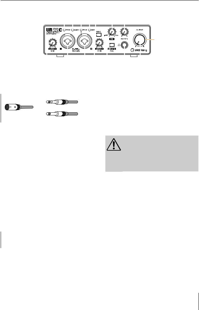
Front Panel
5 6 5 7 9 |
) @ |
|||||||||
|
|
|
|
|
|
|
|
|
|
|
|
|
|
|
|
|
|
|
|
|
|
|
|
|
|
|
|
|
|
|
|
|
$
|
|
|
|
|
|
|
|
|
|
|
|
|
|
|
|
|
|
|
|
|
|
|
|
|
|
|
|
|
|
|
|
|
|
|
|
|
|
|
|
|
|
|
|
|
|
|
|
|
|
|
|
|
|
|
|
|
|
|
|
|
|
|
|
|
|
|
|
|
|
|
|
2 |
|
1 |
|
3 4 8 |
! |
# |
|||||||||||
1 [MIC/LINE 1] jack |
|
|
|
|
|
|
|
|
|
7 [USB] indicator |
|||||||
For connection to a microphone or digital instrument. This jack can be connected to both XLR-type and phone-type (balanced/unbalanced) plugs.
Plug types
Phone-type (balanced)
XLR-type (balanced)
Phone-type (unbalanced)
NOTE
The phantom power will be supplied to the XLR jack connected to the [MIC/LINE 1] jack.
2 [INPUT 1 GAIN] knob
Adjusts the input signal level of the [MIC/LINE 1] jack.
3 [MIC/LINE 2] jack
For connection to a microphone, digital instrument, electric guitar, or electric bass. This jack can be connected to both XLR-type and phone-type (balanced/ unbalanced) plugs.
NOTE
The phantom power will be supplied to the XLR jack connected to the [MIC/LINE 2] jack.
4 [INPUT 2 GAIN] knob
Adjusts the input signal level of the [MIC/LINE 2] jack.
5 [PEAK] indicator
Lights up according to the input signal. Lights up when the input signal is 3 dB below the clipping level.
Setting optimum recording levels
Adjust the [INPUT GAIN] knobs so that the [PEAK] indicator flashes briefly at the loudest input volume.
6 [+48V] indicator
Lights up when the [+48V] switch (phantom power) is turned on.
Lights up when the power is turned on and the unit is communicating with the computer or iOS device. The indicator flashes continuously when the computer or iOS device does not recognize the device.
8 [INPUT 2 HI-Z] switch
Switches the input impedance (on O/off N). Turn this switch on when connecting high impedance instruments, such as an electric guitar or electric bass, directly to the [MIC/LINE 2] jack. When you turn this switch on, use an unbalanced phone plug for connection between the instruments and the [MIC/LINE 2] jack.
CAUTION
To protect your speaker system, leave the monitor speakers turned off when turning the [INPUT 2 HI-Z] switch on/off. It’s also a good idea to turn all output level controls down to their minimum. Neglect of these precautions may result in loud noise bursts that may damage your equipment, your ears, or both.
NOTICE
Do not connect or disconnect any cables while turning on the [INPUT 2 HI-Z] switch. Doing so can damage the connected device and/or the unit itself.
NOTE
•If you use a balanced phone plug, the device will not work correctly.
•When the HI-Z switch is turned on, the signal from the XLRtype is cut off.
9 [MONO] switch
When this switch is on, the input to the [MIC/LINE 1/2] jacks is output to both the [MAIN OUT L/R] jacks and the L/R channel of the [PHONES] jack. When the switch is off, the input to the [MIC/LINE 1] jacks is output to the [MAIN OUT L] jack and the input to the [MIC/LINE 2] jacks is output to the [MAIN OUT R] jack.
For the [PHONES] jack, the input to the [MIC/LINE 1] jacks is output to the L channel and the input to the [MIC/ LINE 2] jacks is output to the R channel.
UR22C Operation Manual 3

Panel Controls and Terminals
) [MIX] knob
Adjusts the signal level balance between the input signal to the [MIC/LINE 1/2] jacks and the signal from an application, such as DAW software. Both of the signals to the [MIC/LINE 1/2] jacks are mixed as a mono signal. Operation of this control knob does not affect the signal sent to a computer.
Using the Mix knob
Turn the [MIX] knob to the [DAW] side if the input volume is high and to the [INPUT] side if the input volume is low. When the knob is turned fully to the [DAW] side, only the input sound from DAW can be heard.
! [PHONES  ] jack
For connection to a set of stereo headphones.
@ [PHONES] knob
Adjusts the output signal level of the [PHONES] jack.
# [OUTPUT] knob
Adjusts the output signal level of the [MAIN OUTPUT] jacks.
$ POWER indicator
Lights up when the power is turned on. The indicator flashes continuously if the power supply is insufficient. In this case, use the USB power adapter or USB mobile battery.
UR22C Operation Manual 4
Panel Controls and Terminals
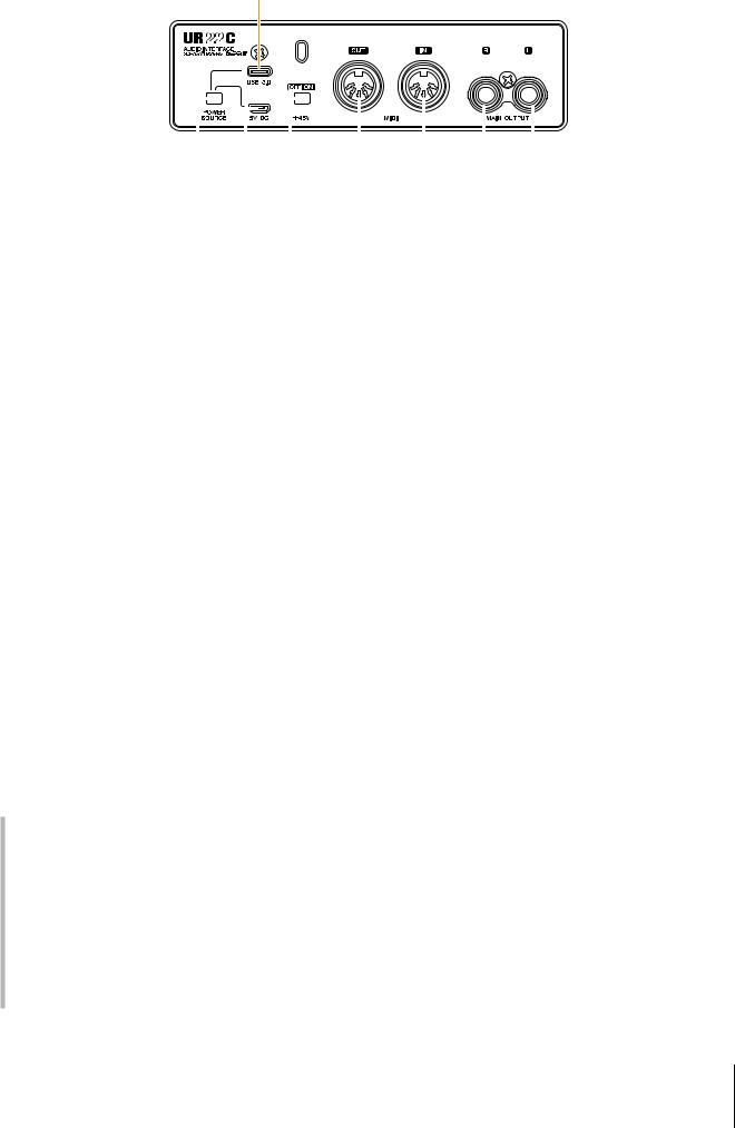
Rear Panel
2
|
|
|
|
|
|
|
|
|
|
|
|
|
|
|
|
|
|
|
|
|
|
|
|
|
|
|
|
|
|
|
|
|
|
|
|
|
|
|
|
|
|
|
|
|
|
|
|
|
|
|
|
|
|
|
|
|
|
|
|
|
|
|
|
|
|
|
|
|
|
|
|
|
|
|
|
|
|
|
|
|
|
|
|
|
|
|
|
|
|
|
|
|
|
|
|
|
|
|
|
|
|
|
|
|
|
|
|
|
|
|
|
|
|
|
|
|
|
|
|
|
|
|
|
|
|
|
|
|
|
|
|
|
|
|
|
|
|
|
|
|
|
|
|
|
|
|
|
|
|
|
|
|
|
|
|
|
|
|
|
|
|
|
|
|
|
|
|
|
|
|
|
|
|
|
|
|
|
|
|
|
|
|
|
|
|
|
|
|
|
|
|
|
|
|
|
|
|
|
|
1 |
|
3 |
4 |
5 |
6 |
|
|
|
|
7 |
|
|
||||||||||||
1 [POWER SOURCE] switch |
|
|
|
|
|
|
|
|
|
|
|
4 [+48V] switch |
|
|
||||||||||
For selecting the port for supplying power to the UR22C. To supply bus power via the [USB 3.0] port, set this switch to the [USB 3.0] side. To supply power via the [5V DC] port, set this switch to the [5V DC] side.
2 [USB 3.0] port
For connection to a computer or iOS device.
NOTICE
When connecting to a computer with a [USB 3.0] port, observe the following to prevent the computer from freezing or shutting down, as well as corruption or even loss of data.
•Before connecting/disconnecting the USB cable, be sure to observe the following points.
-Quit all open software applications on the computer.
-Set all output level controls to the minimum.
•Wait at least six seconds between connecting/ disconnecting the USB cable.
NOTE
Apple accessories may be required when connecting the UR22C with iOS devices. For details, refer to the UR22C Startup Guide.
3 [5V DC] port
For connecting a USB power adapter or USB mobile battery. Use a power supply when connecting the UR22C to a device that does not supply sufficient bus power, such as an iPad. (The UR22C does not include a USB power adapter or USB mobile battery.)
NOTICE
•Read the safety precautions for the USB power adapter or USB mobile battery that you use.
•Use a USB power adapter or USB mobile battery that can supply power in compliance with USB standards with a 5- pin micro USB plug.
Output voltage 4.8 V to 5.2 V Output current 0.9 A or greater
Using the [5V DC] port
Even when the UR22C is connected to a computer, you can supply power via the [5V DC] port by external power supply if the [POWER SOURCE] switch is set to the [5V DC] side. This can be used to avoid power supply problems. For example, ground loops due to differences in voltage potential can occur if the device connected to the UR22C is using the same power outlet as the computer, and audio quality degradation can occur if the power supply from the computer’s USB port is not stable.
Turns the phantom power on/off. When you turn this switch on, phantom power will be supplied to the XLR jack connected to the [MIC/LINE 1/2] jacks. Turn this switch on when using a phantom powered condenser microphone.
NOTICE
When using phantom power, observe the following to prevent noise and possible damage to UR22C or connected equipment.
•Do not connect or disconnect any devices while the phantom power switch is turned to ON.
•Set all output level controls to the minimum before turning the phantom power switch to ON or OFF.
•When connecting devices not requiring phantom power to the [MIC/LINE 1/2] jack, make sure to turn the phantom power switch to OFF.
NOTE
When the phantom power switch is turned on and off, all inputs/ outputs will be muted for a few seconds.
5 [MIDI OUT] jack
For connection to the MIDI IN jack of the MIDI device. Transmits MIDI signals from the computer.
6 [MIDI IN] jack
For connection to the MIDI OUT jack of the MIDI device. Receives and inputs MIDI signals to the computer.
NOTE
•Select [Steinberg UR22C-port1] for the MIDI port when using a MIDI jack with an iOS app. Please note that [Steinberg UR22Cport2] is not available.
•Do not activate dspMixFx when using a MIDI device. This may interfere with stable data transmission/reception.
7 [MAIN OUTPUT L/R] jacks
For connection to monitor speakers. These jacks can be connected to phone-type (balanced/unbalanced) plugs. This outputs the MIX 1 signals. To adjust the output signal level, use the [OUTPUT] knob on the front panel.
UR22C Operation Manual 5
Software
Software
The section explains software operations for using the UR22C with a computer.
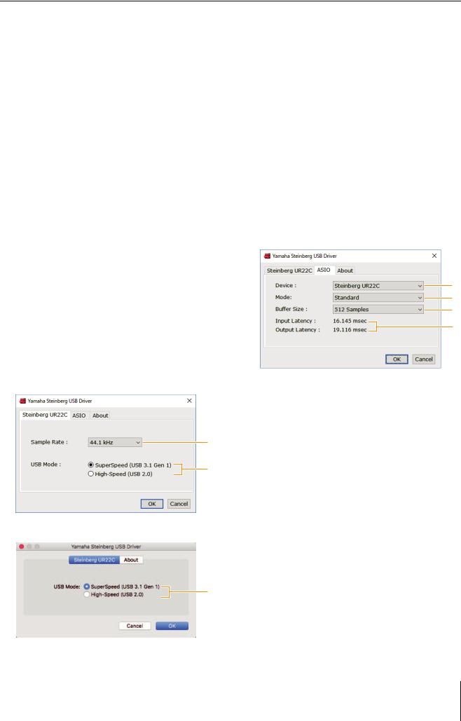
Yamaha Steinberg USB Driver
1 Sample Rate
Lets you select the sample rate of the device.
Settings: 44.1 kHz, 48 kHz, 88.2 kHz, 96 kHz, 176.4 kHz, 192 kHz
NOTE
Yamaha Steinberg USB Driver is a software program that allows communication between the UR22C and a computer. In Control Panel, you can configure the basic settings for the audio driver (Windows) or confirm the audio driver information (Mac).
How to Open the Window
Windows
•From the start menu, select [Yamaha Steinberg USB Driver] [Control Panel].
•From the Cubase series menu, select [Studio] [Studio Setup] [Yamaha Steinberg USB ASIO] [Control Panel].
Click the upper tabs to select the desired window.
The available sample rates may differ depending on the particular DAW you’re using.
2 USB Mode
Lets you select the USB mode. The default setting is SuperSpeed (USB 3.1 Gen 1) mode.
Settings: SuperSpeed (USB 3.1 Gen 1), High-Speed (USB 2.0)
NOTE
If High-Speed (USB 2.0) mode is used, the data bandwidth will become narrower, but this will not affect the functionality of the UR22C. Other performance values such as latency will not change.
ASIO Window (Windows only)
For selecting the ASIO driver settings.
Mac
•Select [Application] [Yamaha Steinberg USB Control Panel]
•From the Cubase series menu, select [Studio] [Studio Setup] [Steinberg UR22C (High Precision)] [Control Panel] [Open Config App]
Steinberg UR22C Window
These windows are for selecting the sample rate and the USB mode.
Windows
1
2
Mac
1
2
3
4
1 Device
Lets you select the device for use with the ASIO driver. This function is available when connecting two or more devices that are compatible with the Yamaha Steinberg USB Driver to the computer.
2 Mode
Lets you select the latency mode.
Settings: Low Latency, Standard, Stable
Sample Rate |
Descriptions |
|
|
Low Latency |
Low latency mode. High-performance |
|
computer is required. |
|
|
Standard |
Standard latency mode. |
|
|
Stable |
High latency mode. This prioritizes |
|
stability for low-performance computer |
|
and high-load projects. |
|
|
2
UR22C Operation Manual 6
3 Buffer Size
Lets you select the buffer size for the ASIO driver. The range varies depending on the specified sample rate. The lower the value of the ASIO buffer size, the lower the value of audio latency.
Sample Rate |
Range |
|
|
44.1 kHz / 48 kHz |
32 Samples – 2048 Samples |
|
|
88.2 kHz / 96 kHz |
64 Samples – 4096 Samples |
|
|
176.4 kHz / 192 kHz |
128 Samples – 8192 Samples |
|
|
4 Input Latency/Output Latency
Indicates the latency (delay time) for the audio input and output in millisecond units.
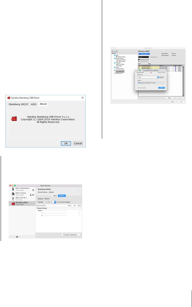
About Window
Indicates the version and copyright information of the audio driver.
How to Select the Sample Rate (Mac)
You can select the sample rate in the [Audio MIDI Setup] window. Select the sample rate from the [Applications] [Utilities] [Audio MIDI Setup] [Format] menu.
Software
How to Select the Buffer Size (Mac)
You can select the buffer size in the settings window for each application (DAW software, etc.).
From the Cubase series menu, select [Studio] [Studio Setup], then click [Control Panel] in [Steinberg UR22C] or [Steinberg UR22C (High Precision)] in the menu on the left side of the window.
The method for opening the settings window is different for each application.
Using with 32-bit Integer processing (Mac)
[Steinberg UR22C] or [Steinberg UR22C (High Precision)] is shown in the [ASIO Driver] setting on the Cubase series program. Select [Steinberg UR22C (High Precision)] when processing at 32-bit integer resolutions between Cubase and the driver.
UR22C Operation Manual 7
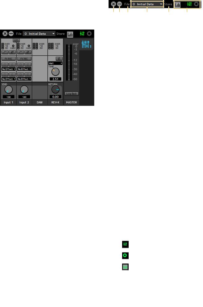
dspMixFx UR-C
This software is for operating the convenient built-in DSP mixer and DSP effects. The DSP mixer allows you to mix up to two input channels down to one stereo output. A number of DSP effects for processing the input signals are also provided, and since the processing/mixing is hardware-based, there is no monitoring latency.
Screenshot
How to Open the Window
Windows
[All Programs] or [All apps] [Steinberg UR22C] [dspMixFx UR-C]
Mac
[Application] [dspMixFx UR-C]
Software
Tool Area
This is the area for configuring the overall common settings of dspMixFx UR-C.
1 2 |
3 |
4 |
5 |
6 |
1 Quit
Quits dspMixFx UR-C.
2 Minimize
Minimizes the dspMixFx UR-C window.
3 File
Provides four different menus for various settings.
Menu |
Descriptions |
|
|
Open |
Opens the settings file of dspMixFx |
|
UR-C. |
|
|
Save |
Saves the settings file of dspMixFx UR- |
|
C to a computer. |
|
|
Import Scene |
Imports a scene from the settings file of |
|
dspMixFx UR-C. Select the desired |
|
settings file of dspMixFx UR-C and |
|
import the desired scene on the left |
|
side of the [IMPORT SCENE] window. |
|
The window appears after the file is |
|
selected in the file selection dialog. |
|
Select the destination for importing on |
|
the right side of the window. Click [OK] |
|
to import it. |
|
|
Initialize All Scenes |
Initialize all the saved scenes. |
|
|
4 Scene
Indicates the scene name. You can change the scene name by clicking on it. Clicking the button on the right opens the window for calling up other scenes. Call up the desired scene by clicking it. To cancel calling up the scene, click outside of the window.
5 Store
Opens the Scene Store window. Enter the desired scene name into the STORE NAME field. Select the destination for storing the scene in the No. NAME field. Click [OK] to store the scene.
6 Selecting windows
Selects the desired dspMixFx UR-C window. The selected window icon lights in red.
Menu |
Description |
|
|
|
Main window |
|
|
|
Setup window |
|
|
|
Information window |
|
|
UR22C Operation Manual 8

Main Window
This window is for configuring the entire signal flow.
Channel Area (page 9) |
MIX Area (page 11) |
DAW Area (page 10)
REV-X Area (page 10)
Master Area (page 11)
Channel Area
This is the area for configuring the input channel settings.
1 |
|
|
|
|
|
3 |
|||
2 |
|
|
|
|
|
||||
|
|
|
|
||||||
4 |
|
|
|
|
|
|
|
5 |
|
|
|
|
|
|
|
|
|||
|
|
|
|
|
|
||||
6 |
|
|
|
|
|
|
8 |
||
|
|
|
|
|
|
||||
7 |
|
|
|
|
|
|
|||
|
|
|
|
|
|||||
9 |
|
|
|
|
|
|
|||
)
!
1 Channel Link
Turns on (lit) and off (unlit) the channel link function of two adjacent channels. When this is on, two mono channels will become one stereo channel.
2 Level Meter
Indicates the signal level.
3 +48V
Indicates the on/off status of the phantom power function of the device.
Software
4 High Pass Filter
Turns on (lit) and off (unlit) the high pass filter. To select the cutoff frequency of the high pass filter, use the “Setup Window” (page 12) in the section “dspMixFx UR-C.”
5 Phase
Turns on (lit) and off (unlit) the phase inversion of the signal.
6 FX REC
Turn the FX REC (effect recording) on and off.
Settings |
Description |
|
|
On (lit) |
Applies an effect to both the monitor |
|
signal (sent to the device) and the |
|
recording signal (sent to the DAW |
|
software). |
|
|
Off (unlit) |
Applies an effect to only the monitor |
|
signal (sent to the device). |
|
|
7 Effect On/Off
Turns the Effect on (lit) and off (unlit).
8 Effect Edit
Opens (lit) and closes (unlit) the selected effect setup window.
9 Effect Type
Selects the effect type.
Settings: NoEffect, Ch.Strip, Clean, Crunch, Lead, Drive
NOTE
The maximum number of Channel Strip and Guitar Amp Classics iterations which can be used simultaneously is limited. Refer to the “Limitations on the use of effects” (page 33).
) REV-X Send
Adjusts the signal level which is sent to REV-X.
Range: -∞ dB − +6.00 dB
! REV-X Send Value
Displays and adjusts the REV-X send value. Enable editing of the value by double clicking the number.
UR22C Operation Manual 9

DAW Area
This is the area for configuring the DAW channel settings.
1
1 Level Meter
Indicates the signal level.
Software
REV-X Area
This is the area for configuring the REV-X channel settings.
1
2
3
4
5
6
1 REV-X Edit
Opens (lit) and closes (unlit) the “REV-X” (page 18) setup window.
2 REV-X Type
Selects the REV-X type.
Settings: Hall, Room, Plate
3 REV-X Time
Adjusts the reverb time of REV-X. This parameter links to Room Size. The adjustable range varies depending on REV-X type.
REV-X Type |
Range |
|
|
Hall |
0.103 sec − 31.0 sec |
|
|
Room |
0.152 sec − 45.3 sec |
|
|
Plate |
0.176 sec − 52.0 sec |
|
|
4 REV-X Time Value
Displays and adjusts the REV-X Time value. Enable editing of the value by double clicking the number.
5 REV-X Return
Adjusts the return level of REV-X.
6 REV-X Return Value
Displays and adjusts the REV-X Return value. Enable editing of the value by double clicking the number.
UR22C Operation Manual 10
MASTER Area
This is the area for configuring the master channel settings.
1
2
1 Level Meter
Indicates the signal level.
2 Loop Back
Turns the Loopback function on (lit) and off (unlit).
What is Loopback?
Loopback is a convenient function for broadcasting over the Internet. It mixes the input audio signals (such as microphone and guitar) with the audio signals playing back in the software in the computer into two channels in the UR22C, and sends them back to the computer. Refer to the section “Signal Flow” (page 34).
If the Loopback function is on while you are monitoring input signals from the UR22C via DAW software, it will cause loud noise. This is because an infinite loop of the audio signal is generated between the UR22C and the DAW software. When using the loopback function, turn off the monitor functions on your DAW software.
BGM Deliver
UR22C
MIX Area
This is the area for selecting the MIX you want to configure. The UR22C can be set only to MIX1.
Software
Meter Window
This window is for showing the meter at the top of the Main window.
1
1 Level Meter
Indicates the signal level. Peak hold is normally set to on.
Display color |
Description |
|
|
Green |
Up to -18dB |
|
|
Yellow |
Up to 0dB |
|
|
Red |
CLIP |
|
|
UR22C Operation Manual 11
Software
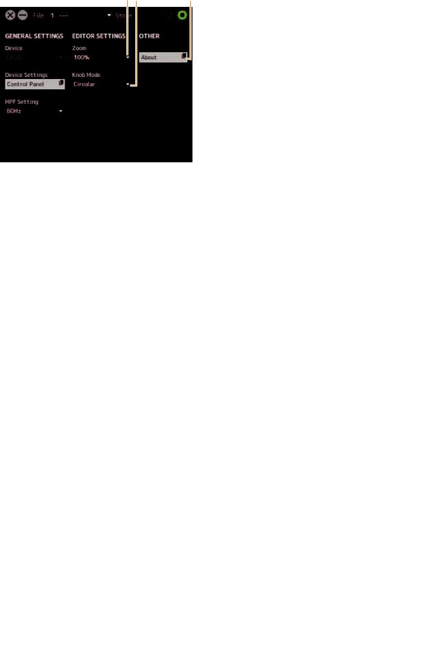
Setup Window
This window is for configuring the common settings of the device.
45 6
1
2
3
1 Device
Selects the device when simultaneously connecting one or more devices that are capable with dspMixFx.
2 Device Settings
Opens the Control Panel.
3 HPF Setting
Selects the cutoff frequency of the high pass filter.
Settings: 120 Hz, 100 Hz, 80 Hz, 60 Hz, 40 Hz
4 Zoom
Changes the window size.
Settings: 100%, 150%, 200%, 250%, 300%
5 Knob Mode
Selects the method of operating the knobs on dspMixFx
UR-C.
Settings |
Description |
|
|
Circular |
Drag in a circular motion to increase and |
|
decrease the parameter. Drag on a dial |
|
clockwise to increase, and counterclockwise to |
|
decrease. If you click any point on the knob, |
|
the parameter will jump there instantly. |
|
|
Linear |
Drag in a linear motion to increase and |
|
decrease the parameter. Drag upward or |
|
rightward to increase, and downward or |
|
leftward to decrease. Even if you click any point |
|
on the knob, the parameter will not jump there. |
|
|
6 About
Indicates the version of the firmware and software.
UR22C Operation Manual 12
Loading...