


USB AUDIO INTERFACE
EN
DE
FR
ES
PT
I T
ZH
JA

Contents |
|
Message from the Development Team ....... |
2 |
Panel Controls and Terminals .............. |
3 |
Front Panel ................................................... |
3 |
Rear Panel .................................................... |
5 |
Software........................................................ |
6 |
Using the UR242................................... |
22 |
Connection Examples ................................. |
22 |
Configuring Audio Driver Settings on the |
|
DAW Software ............................................ |
23 |
Recording/Playback .................................... |
23 |
Troubleshooting................................... |
25 |
Appendix............................................... |
27 |
Limitations on the use of effects ................. |
27 |
Block Diagrams........................................... |
28 |
Message from the
Development Team
Thank you for choosing the UR242 USB Audio Interface.
The UR242 offers the same sonic quality and functions as the previously released UR44, but a compact design with two microphone preamps rather than four makes it closer in size to the UR22.
Like all UR series models, D-PRE microphone preamp parts selection and circuit design have been carried out with meticulous care and attention to detail. The highs are extended and open, the midrange dense and detailed, and the lows deliver solid punch. The UR242 inherits the highly regarded sonic character of the Yamaha n8 and n12 Digital Mixing Studios, the Steinberg MR816 series audio interfaces, and of course the UR series.
The UR242 combo inputs feature pads that allow a wide range of sources, from high sensitivity microphones to line level devices, to be connected while fully retaining even the subtlest musical nuances. The level controls have been designed with extra care to ensure minimum noise when recording.
No compromises have been made in the outputs that drive the monitor speakers either. Every effort has been made to ensure that spatial depth is accurately reproduced so that our users can accurately hear width, depth, and the tiniest variations in loudness in exquisite detail.
Built-in DSP delivers the same refined sonic quality and creative potential as the high-end models, with features like True Integrated Monitoring for ultra-low-latency recording, REV-X reverb effects, a Channel Strip that is packed with professional compression and equalization know-how, and Guitar Amp Classics featuring modeled guitar amplifiers from the vintage era through to heavier modern sounds.
Expandability is enhanced by iOS support that provides simple plug-and-play operation with the Apple iPad. With an iPad and an iOS compatible audio application such as Steinberg Cubasis it is easy to record and create with impressive quality just about anywhere. There’s also a loopback function that can be handy for video delivery in today’s fast-paced Internet environment.
High-quality recording that anyone can enjoy is here. We sincerely hope that the UR242 will contribute to the creative efforts of beginners as well as professionals.
The Steinberg Hardware
Development Team
UR242 Operation Manual 2
Panel Controls and Terminals
Panel Controls and Terminals
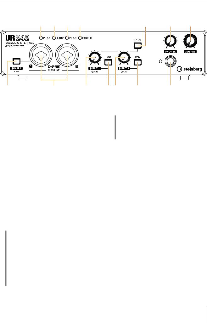
Front Panel
3 4 3 5 |
9 |
) |
! |
1 |
2 |
6 |
1[INPUT 1 HI-Z] switch
Switches the input impedance (on O/ off N). Turn this switch on when connecting high impedance instruments, such as an electric guitar or electric bass, directly to the [MIC/LINE 1] jack. When you turn this switch on, use an unbalanced phone plug for connection between the instruments and the [MIC/LINE 1] jack. If you use a balanced phone plug, this device will not work correctly.
 CAUTION
7 8 |
7 |
@ |
3[PEAK] indicator
Lights up when the input signal is 3 dB below the clipping level.
HINT
Setting optimum recording levels
Adjust the gain knobs so that the [PEAK] indicator flashes briefly at the loudest input volume.
4[+48V] indicator
•Do not connect or disconnect a device while turning on the [INPUT 1 HI-Z] switch. Doing so can damage the connected device and/or the unit itself.
•To protect your speaker system, leave the monitor speakers turned off when turning the [INPUT 1 HI-Z] switch on/ off. It’s also a good idea to turn all output level controls down to their minimum. Neglect of these precautions may result in loud noise bursts that may damage your equipment, your ears, or both.
2[MIC/LINE 1/2] jack
For connecting to a microphone or digital instrument. This jack can be connected to both XLR-type and phone-type (balanced/unbalanced).
HINT
Proper use of the HI-Z or LINE inputs
HI-Z:
•Guitar and bass with passive pickups (not battery powered)
LINE:
•Effect device, preamp, direct box
•Guitar and bass with active pickups (battery powered)
•Digital instruments, such as synthesizers
Lights up when the [+48V] switch (phantom power) is turned on.
5[POWER] indicator
Lights up when the power is turned on. If the computer or iPad does not recognize the device, this flashes continuously.
6[INPUT 1 GAIN] knob
Adjusts the input signal level of the [MIC/LINE 1] jack.
7[PAD] switch
Turning the switch on (O) will attenuate the sound input to the unit. If you hear distortion, turn this switch on (O).
8[INPUT 2 GAIN] knob
Adjusts the input signal level of the [MIC/LINE 2] jack.
UR242 Operation Manual 3

Panel Controls and Terminals
9[+48V] switch
Turns the phantom power on (O) and off (N). When you turn this switch on, phantom power will be supplied to the [MIC/LINE 1/2] jack. Turn this switch on when using a phantom powered condenser microphone.
Phantom Power Precautions
NOTICE
Always turn the phantom power switch to OFF when it is not required.
When using phantom power, observe the following to prevent noise and possible damage to UR242 or connected equipment.
•When connecting devices not requiring phantom power to the [MIC/LINE 1/2] jack, make sure to turn the phantom power switch to OFF.
•Set all output level controls to the minimum before turning the phantom power switch to ON or OFF.
•Do not connect or disconnect any devices while the phantom power switch is turned to ON.
)[PHONES] knob
Adjusts the output signal level of the [PHONES] jack.
![OUTPUT] knob
Adjusts the output signal level of the [LINE OUTPUT] jacks.
@[PHONES  ] jack
For connecting a set of headphones.
UR242 Operation Manual 4
Panel Controls and Terminals
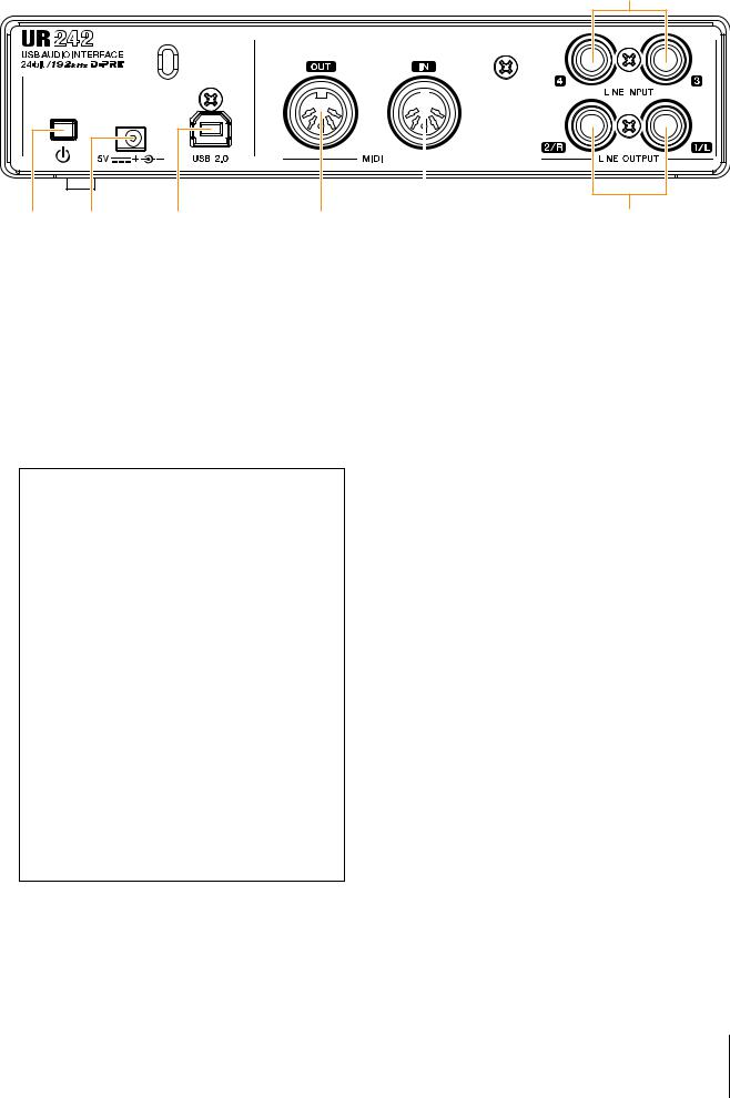
Rear Panel
6
1 |
2 |
3 |
4 |
1[  ] (Standby/On) switch
Sets the power of the device to On (O) or Standby (N).
2DC IN [5V]
For connecting to the AC power adaptor.
3[USB 2.0] terminal
For connecting to a computer or iPad. Automatically discriminated whether connecting device is a computer or iPad.
USB Terminal Precautions
Be sure to observe the following points when connecting the device to the computer’s USB interface. Failing to do so may result in the computer freezing or shutting down, as well as corruption or even loss of data. If the device or computer does freeze, restart the application or computer.
NOTICE
•Use an AB type USB cable. USB 3.0 cables are not supported.
•Be sure to wake the computer from sleep/ suspended/standby mode before connecting it to the UR242 with a USB cable.
•Before connecting/disconnecting the USB cable, quit all open software applications on the computer.
•Before connecting or disconnecting the USB cable from the [USB2.0] terminal, be sure to set all output level controls to the minimum.
•Do not connect/disconnect the USB cable in rapid succession. Wait at least six seconds between connecting/disconnecting the USB cable.
4[MIDI OUT] jack
For connecting to the MIDI IN jack of a MIDI device. This transmits MIDI signals from the computer.
|
|
|
|
|
|
|
|
|
|
|
|
|
|
|
|
|
|
|
|
|
|
|
|
|
|
|
|
|
|
|
|
|
|
|
|
|
|
|
|
|
|
|
|
|
|
|
|
|
|
|
|
|
|
|
|
|
|
|
|
|
|
|
|
|
|
|
|
|
|
|
|
|
|
|
|
|
|
|
|
|
|
|
|
|
|
|
|
|
|
|
|
|
|
|
|
|
|
|
|
|
|
|
|
|
|
|
|
|
|
|
|
|
|
|
|
|
|
|
|
|
|
|
|
|
|
|
|
|
|
|
|
|
|
|
|
|
|
|
|
|
|
|
|
|
|
|
|
|
|
|
|
|
|
|
|
|
|
|
|
|
|
|
|
|
|
|
|
|
|
|
|
|
|
|
|
|
|
|
|
|
|
|
|
|
|
|
|
|
|
|
|
|
|
|
|
|
|
|
|
|
|
|
|
7 |
|
|
|
|
|||||||||||
5 |
|
|
|
|
|||||||||||||||||
5[MIDI IN] jack
For connecting to the MIDI OUT jack of the MIDI device. This receives and inputs MIDI signals to the computer.
NOTE
Select [Steinberg UR242-1] for the MIDI port when using a MIDI jack with an iPad application. Please note that [Steinberg UR242-2] is not available.
6[LINE INPUT 3/4] jacks
For connecting to digital instrument or a mixer. These jacks can be connected to phone-type (balanced/ unbalanced). You can select the input signal level of the [LINE INPUT 3/4] jacks between +4 dBu and -10 dBV. Select +4 dBu when connecting a professional audio device, and select -10 dBV when connecting a consumer device. The default initial setting is -10 dBu. To select the input signal level, use the “Setup Window” (page 11) in the section “dspMixFx UR242” or the “Settings Window” (page 16) in the “Dedicated Windows for Cubase Series.”
7[LINE OUTPUT 1/L 2/R] jacks
For connecting to external devices with line level signals. These jacks can be connected to phone-type (balanced/unbalanced)
UR242 Operation Manual 5
Software
This section explains software operations for using the UR242 with a computer.
Panel Controls and Terminals
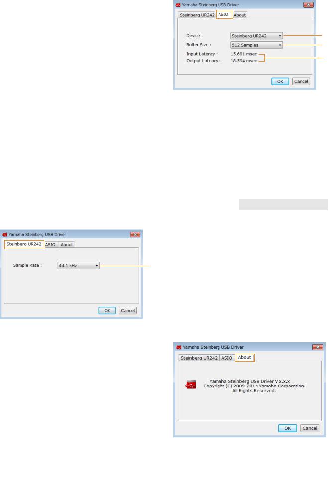
ASIO Window
For selecting the ASIO driver settings.
Yamaha Steinberg USB Driver
Yamaha Steinberg USB Driver is a software program that allows communication between the UR242 and a computer. In Control Panel, you can configure the basic settings for the audio driver (Windows) or confirm the audio driver information (Mac).
Windows
How to Open the Window
•Select [Control Panel] [Hardware and Sound] or [Sounds, Speech, and Audio Devices] [Yamaha Steinberg USB Driver].
•From the Cubase series menu, select [Devices] [Device Setup...] [Yamaha Steinberg USB ASIO] [Control Panel].
How to Select Windows
Click the upper tabs to select the desired window.
Steinberg UR242 Window
This window is for selecting the sample rate.
1
1 Sample Rate
Lets you select the sample rate of the device. Options: 44.1 kHz, 48 kHz, 88.2 kHz, 96 kHz,
176.4 kHz, 192 kHz
NOTE
The available sample rates may differ depending on the particular DAW you're using.
1
2
3
1Device
Lets you select the device for use with the ASIO driver. (This function is available when connecting two or more devices that are compatible with the Yamaha Steinberg USB Driver to the computer.)
2 Buffer Size
Lets you select the buffer size for the ASIO driver. The range varies depending on the specified sample rate. The lower the value of the ASIO buffer size, the lower the value of audio latency
Sample Rate |
Range |
|
|
44.1 kHz / 48 kHz |
64 samples – 2048 samples |
|
|
88.2 kHz / 96 kHz |
128 samples – 4096 samples |
|
|
176.4 kHz / 192 kHz |
256 samples – 8192 samples |
|
|
3 Input Latency/Output Latency
Indicates the latency (delay time) for the audio input and output in millisecond units.
About Window
Indicates the version and copyright information of the audio driver.
UR242 Operation Manual 6
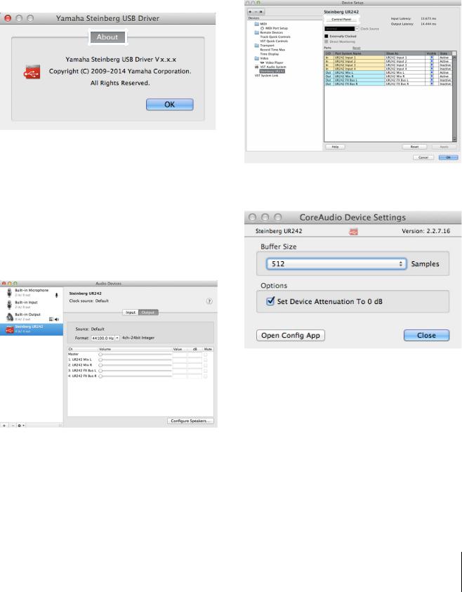
Mac
How to Open the Window
Panel Controls and Terminals
How to Select the Buffer Size
You can select the buffer size in the settings window for each application (DAW software, etc.).
•Select [System Preferences] [Yamaha Steinberg USB].
1. From the Cubase series menu, select [Devices]
•From the Cubase series menu, select [Devices]
[Device Setup...] [Steinberg UR242] [Control Panel] |
[Device Setup...]. |
|
|
[Open Config App]. |
NOTE |
|
The method for opening the settings window is different for |
|
each application. |
About Window |
2. Click [Control Panel] in [Steinberg UR242] in the |
|||||
Indicates the version and copyright information of the audio |
||||||
menu on the left side of the window. |
||||||
driver. |
|
|
|
|||
|
|
|
|
|
|
|
|
|
|
|
|
|
|
|
|
|
|
|
|
|
|
|
|
|
|
|
|
How to Select the Sample Rate
You can select the sample rate in [Audio MIDI Setup] |
The window for selecting the buffer size appears. |
|
|
window. |
|
1.Select [Applications] [Utilities] [Audio MIDI
Setup].
2.Select the sample rate from the [Format] menu.
UR242 Operation Manual 7

dspMixFx UR242
This software is for operating the convenient built-in DSP mixer and DSP effects. The DSP mixer allows you to mix up to four input channels down to one stereo output. A number of DSP effects for processing the input signals are also provided, and since the processing/mixing is hardware-based, there is no monitoring latency.
NOTE
You cannot operate dspMixFx UR242 while a Cubase series DAW is running. When Cubase is running, configure the DSP mixer and DSP effect from “Dedicated Windows for Cubase Series” (page 13).
How to Open the Window
Windows
[All Programs] or [All apps] [Steinberg UR242] [dspMixFx UR242]
Mac
[Applications] [dspMixFx UR242]
Controls and Functions
Tool Area
This is the area for configuring the overall common settings of dspMixFx UR242.
12 3 |
4 |
5 |
6 |
7 |
1Quit
Quits dspMixFx UR242.
2Minimize
Minimizes the dspMixFx UR242 window.
3Menu
Provides four different menus for various settings.
Menu |
Description |
|
|
Open |
Opens the settings file of dspMixFx |
|
UR242. |
|
|
Save |
Saves the settings file of dspMixFx |
|
UR242 to a computer. |
|
|
Import Scene |
Imports a scene from the settings file of |
|
dspMixFx UR242. Select the desired |
|
settings file of dspMixFx UR242 and |
|
import the desired scene on the left side |
|
of the [IMPORT SCENE] window. The |
|
window appears after the file is selected |
|
in the file selection dialog. Select the |
|
destination for importing on the right side |
|
of the window. Click [OK] to import it. |
|
|
Initialize All Scenes |
Deletes all the saved scenes. |
|
|
Panel Controls and Terminals
4Scene
Indicates the scene name. You can change the scene name by clicking on it. Clicking the button on the right opens the window for calling up other scenes. Call up the desired scene by clicking it. To cancel calling up the scene, click outside of the window.
5STORE
Opens the Scene Store window. Enter the desired scene name into the STORE NAME field. Select the destination for storing the scene in the No. NAME field. Click [OK] to store the scene.
6 Selecting windows
Selects the desired dspMixFx UR242 window. The selected window icon lights in red.
Menu Description
Main window (page 8)
Setup window (page 11)
Information window (page 12)
7Help
Opens the Operation Manual (this manual).
Main Window
This window is for configuring the entire signal flow.
Channel Area (page 9) |
MIX Area (page 11) |
|||||
|
|
|
|
|
|
|
|
|
|
|
|
|
|
|
|
|
|
|
|
|
|
|
|
|
|
|
|
DAW Area (page 10)
Master Area (page 10)
Headphone Area (page 11)
UR242 Operation Manual 8
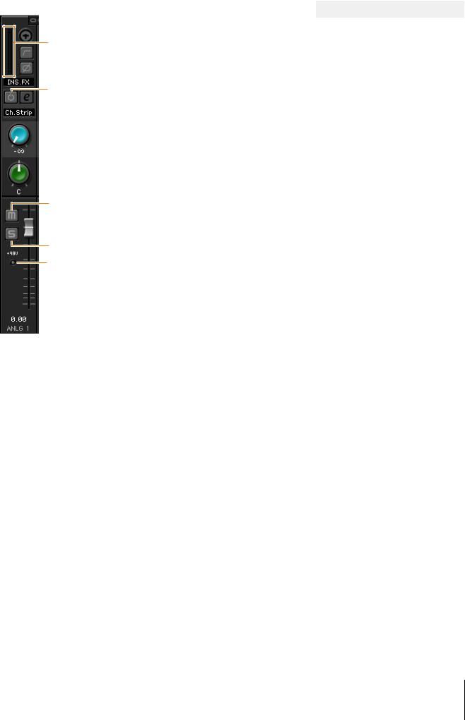
Channel Area
This is the area for configuring the input channel settings.
 1
1
2  3
3
 4
4
 5
5
6
 7
7
 8
8
 9
9
 )
)
!
 $
$
@
#
1 Channel Link
Turns on (lit) and off (dark) the channel link function of two adjacent channels. When this is on, two mono channels will become one stereo channel.
2 Level Meter
Indicates the signal level.
3 High Pass Filter
Turns on (lit) and off (dark) the high pass filter (not available on [LINE INPUT 3/4] ). To select the cutoff frequency of the high pass filter, use the “Setup Window” (page 11) in the section “dspMixFx UR242.”
4Phase
Turns on (lit) and off (dark) the phase inversion of the signal.
Panel Controls and Terminals
5 Effect Insertion location
Selects the insertion location of an effect.
Options |
Description |
|
|
MON.FX |
Applies an effect to only the monitor |
|
signal (sent to the device). |
|
|
INS.FX |
Applies an effect to both the monitor |
|
signal (sent to the device) and the |
|
recording signal (sent to the DAW |
|
software). |
|
|
6 Effect On/Off
Turns the Effect on (lit) and off (dark).
7 Effect Edit
Opens (lit) and closes (dark) the selected effect setup window.
8 Effect Type
Select the effect type.
Options: Ch.Strip, Clean, Crunch, Lead, Drive
NOTE
The maximum number of Channel Strip and Guitar Amp Classics iterations which can be used simultaneously is limited. Refer to the “Limitations on the use of effects” (page 27).
9 REV-X Send
Adjusts the signal level which is sent to REV-X. Range: - ∞ dB – +6.00 dB
)Pan
Adjusts the pan. Range: L16 – C – R16
!Mute
Turns the mute function on (lit) and off (dark).
@Solo
Turns the solo function on (lit) and off (dark).
#+48V
Indicates the on/off status of the phantom power function of the device.
$Fader
Adjusts the signal level. Range: - ∞ dB – +6.00 dB
UR242 Operation Manual 9
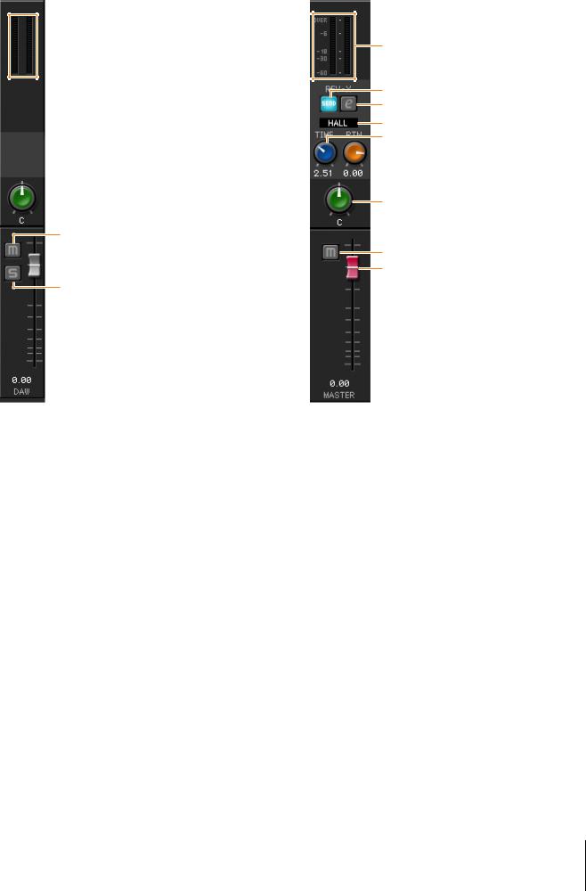
DAW Area
This is the area for configuring the DAW channel settings.
 1
1
 2
2
3
 5 4
5 4
1 Level Meter
Indicates the signal level.
2Pan
Adjusts the pan. Range: L16 – C – R16
3Mute
Turns the mute function on (lit) and off (dark).
4Solo
Turns the solo function on (lit) and off (dark).
5Fader
Adjusts the signal level. Range: - ∞ dB – +6.00 dB
Panel Controls and Terminals
Master Area
This is the area for configuring the master channel settings.
1
2
3
4
5
 6
6
7
8
9
1 Level Meter
Indicates the signal level.
2 REV-X Send On
Indicates that REV-X Send is on. This is normally set to On.
3 REV-X Edit
Opens (lit) and closes (dark) the “REV-X” (page 18) setup window.
4 REV-X Type
Selects the REV-X type.
Options: Hall, Room, Plate
5 REV-X Time
Adjusts the reverb time of REV-X. This parameter links to Room Size. The adjustable range varies depending on REV-X type.
REV-X Type |
Range |
|
|
Hall |
0.103 sec – 31.0 sec |
|
|
Room |
0.152 sec – 45.3 sec |
|
|
Plate |
0.176 sec – 52.0 sec |
|
|
UR242 Operation Manual 10
 Loading...