


 Loading...
XR-1800/1803/1804
SERVICE MANUAL
AEP Model
UK Model
E Model
XR-1800
East European Model
XR-1803
Saudi Arabia Model
XR-1804
Photo: XR-1804
Model Name Using Similar Mechanism |
NEW |
|
|
Tape Transport Mechanism Type |
MG-36SZ9-32 |
|
|
SPECIFICATIONS
– Continued on next page –
XR-1800: AEP, UK Model/XR-1803
FM/MW/LW CASSETTE CAR STEREO
XR-1800: E Model
FM/AM CASSETTE CAR STEREO
XR-1804
FM/MW/SW CASSETTE CAR STEREO
MICROFILM
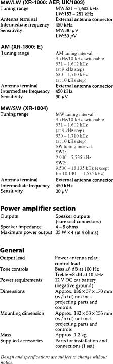
TABLE OF CONTENTS
1.GENERAL
|
Button Locations ............................................................. |
3 |
|
Setting the Clock ............................................................. |
3 |
|
Installation ....................................................................... |
4 |
|
Connections ..................................................................... |
4 |
2. |
DISASSEMBLY ......................................................... |
6 |
3. |
MECHANICAL ADJUSTMENTS ....................... |
10 |
4.ELECTRICAL ADJUSTMENTS
Tape Deck Section .......................................................... |
10 |
Tuner Section .................................................................. |
11 |
5.DIAGRAMS
5-1. IC Pin Function Description ........................................... |
14 |
|
5-2. Note for Printed Wriring Boards and |
|
|
|
Schematic Diagrams ....................................................... |
16 |
5-3. |
Printed Wiring Board – Main Section – ........................ |
17 |
5-4. Schematic Diagram – Main Section (1/2) – ................... |
19 |
|
5-5. Schematic Diagram – Main Section (2/2) – ................... |
21 |
|
5-6. |
Printed Wiring Board – PANEL Section – .................... |
23 |
5-7. |
Schematic Diagram – PANEL Section – ....................... |
23 |
6. |
EXPLODED VIEWS ................................................ |
26 |
7. |
ELECTRICAL PARTS LIST ............................... |
32 |
Flexible Circuit Board Repairing
•Keep the temperature of the soldering iron around 270 ˚C during repairing.
•Do not touch the soldering iron on the same conductor of the circuit board (within 3 times).
•Be careful not to apply force on the conductor when soldering or unsoldering.
Notes on chip component replacement
•Never reuse a disconnected chip component.
•Notice that the minus side of a tantalum capacitor may be damaged by heat.
– 2 –

SECTION 1 GENERAL
This section is extracted from instruction manual.
– 3 –

– 4 –

– 5 –

SECTION 2
DISASSEMBLY
Note: Follow the disassembly procedure in the numerical order given.
COVER ASS’Y
3 cover ass’y
2
1
2 
1
MECHANISM DECK BLOCK
1 two screws |
1 two screws |
|
(PTT2.6 × 6) |
(PTT2.6 × 6) |
|
2 connector |
3 mechanism deck block |
|
(CN901) |
||
|
– 6 –
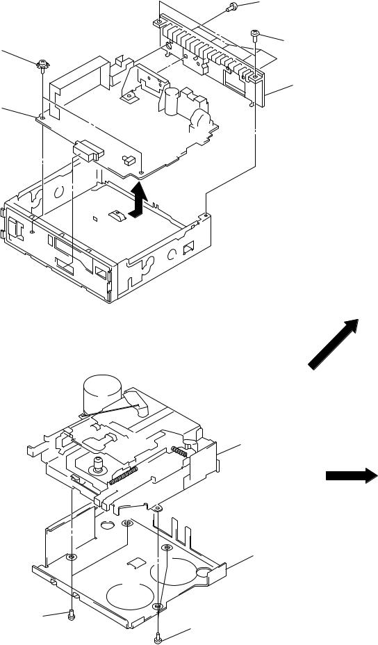
MAIN BOARD, HEAT SINK
3two screws (ground point)
4main board
MECHANISM DECK (MG-36SZ9-32)
1two screws
(P2.6 × 4)
1five screws (PTT2.6 × 8)
1two screws (PTT2.6 × 6)
2heat sink
3mechanism deck (MG-36SZ9-32)
2bracket (MD)
1two screws
(P2.6 × 4)
– 7 –
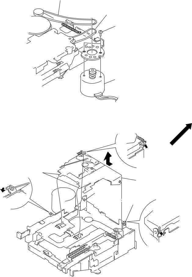
MOTOR ASS’Y (CAPSTAN/REEL) (M901)
2 belt
2 belt
1 two screws
(P2 × 3)
3 motor ass’y (CAPSTAN/REEL)
(M901)
CASSETTE HANGER (X)
1 Remove the claw toward direction.
4 two claws
5 cassette hanger
3 boss
3 boss
2Remove the return link toward direction.
1 Remove the claw toward direction.
– 8 –

CASSETTE HOLDER (X)
2 Removal the cassette holder (x) to direction of the arrow.
A 1 Push an arrow A part.
– 9 –

SECTION 3
MECHANICAL ADJUSTMENTS
1. Clean the following parts with a denatured-alcohol-moistened
swab: |
|
playback head |
pinch roller |
rubber belt |
capstan |
idler |
|
2.Demagnetize the playback head with a head demagnetizer.
3.Do not use a magnetized screwdriver for the adjustments.
4.The adjustments should be performed with the power supply voltage (14.4 V) unless otherwise noted.
• Torque Measurement
Mode |
Torque Meter |
Meter Reading |
|
|
|
|
|
Forward |
CQ-102C |
25 – 55 g•cm |
|
(0.35 – 0.76 oz•inch) |
|||
|
|
||
Forward |
CQ-102C |
1.5 – 4 g•cm |
|
Back Tension |
(0.02 – 0.06 oz•inch) |
||
|
|||
|
|
|
|
Reverse |
CQ-102RC |
25 – 55 g•cm |
|
(0.35 – 0.76 oz•inch) |
|||
|
|
||
|
|
|
|
Reverse |
CQ-102RC |
1.5 – 4 g•cm |
|
Back Tension |
(0.02 – 0.06 oz•inch) |
||
|
|||
FF, REW |
CQ-201B |
50 – 150 g•cm |
|
(0.69 – 2.08 oz•inch) |
|||
|
|
• Tape Tension Measurement
Mode |
Tension Meter |
Meter Reading |
Forward |
CQ-403A |
more than 60 g |
|
|
|
Reverse |
CQ-403R |
(more than 2.12 oz) |
|
|
|
SECTION 4
ELECTRICAL ADJUSTMENTS
TAPE DECK SECTION 
 0 dB= 0.775 V
1.The adjustments should be performed in the order given in this service manual.
2.The adjustments should be performed for both L-CH and R-CH.
Test Tape
Type |
Signal |
Used for |
P-4-A063 |
6.3 kHz, –10 dB |
head azimuth adjustment |
|
|
|
WS-48A |
3 kHz, 0 dB |
tape speed adjustment |
PB Head Azimuth Adjustment
Procedure:
1. Put the set into the FWD PB mode.
test tape |
level |
|
P-4-A063 |
||
meter |
||
(6.3 kHz, –10 dB) |
||
4 Ω |
||
|
||
set |
+ |
|
– |
||
|
||
|
speaker out terminal |
2.Turn the screw and check the output peak value. Adjust the screw so that the peak value in channels L and R coincides within 2 dB.
L-CH |
within |
|
2 dB |
|
|
peak |
|
within |
output |
|
|
|
2 dB |
|
level |
|
|
R-CH |
|
|
peak |
|
angle |
screw |
|
|
position |
L-CH R-CH |
|
|
peak |
peak |
3. Check the phase in the FWD PB mode.
test tape |
|
|
|
P-4-A063 |
|
|
|
(6.3 kHz, –10 dB) |
|
oscilloscope |
|
L-CH |
4 Ω |
|
|
set |
|
V+ |
+H |
|
|
– |
– |
R-CH |
4 Ω |
|
|
speaker out terminal |
|
||
Screen pattern |
|
||
in phase 45 ° |
90 |
° 135 ° 180 ° |
|
good |
|
wrong |
|
– 10 –
4.Repeat the above adjustment for the REV PB mode.
5.Check that output level difference between FWD PB mode and REV PB mode is within 4 dB.
Adjustment Location: PB head
FWD ü
ï
ýadjustment ïscrews
REV þ
See the adjustment location from on page 13 for the adjustment.
Tape Speed Adjustment
Setting:
|
|
speed checker |
|
|
or |
test tape |
|
frequency counter |
WS-48A |
|
|
(3 kHz, 0 dB) |
4 |
Ω |
|
||
|
set |
– + |
|
|
|
|
speaker out terminal |
|
Procedure:
1.Put the set into the FWD PB mode.
2.Adjust adjustment resistor for inside capstan motor so that the reading on the speed checker or frequency counter becomes in specification.
Specification: Constant speed
Speed checker |
|
Frequency counter |
–2 to +3% |
|
2,940 to 3,090 Hz |
|
|
|
Adjustment Location: See page 13. |
|
|
TUNER SECTION
XR-1800 E model, a tuner section is no adjustment.
0 dB=1 µV
Cautions during repair
When the tuner unit is defective, replace it by a new one because its internal block is difficult to repair.
Note: Adjust the tuner section in the sequence shown below.
1.FM Auto Scan/Stop Level Adjustment
2.FM Noise Focus Adjustment
3.FM Stereo Separation Adjustment
4.MW Auto Scan/Stop Level Adjustment
FM Auto Scan/Stop Level Adjustment
Setting:
[TUNER] button: FM 1
FREQUENCY SELECT switch: FM50 k (XR-1804 only)
FM RF signal |
dummy |
|
0.1pF |
generator |
|
|
|
antenna |
|
|
|
|
|
antenna |
|
|
50 Ω |
|
|
|
|
jack (CN900) |
|
|
50 Ω |
|
set |
Carrier frequency : 98.0 MHz |
µV) |
||
Output level |
: 28 dB (25.1 |
||
Mode |
: mono |
|
|
Modulation |
: 1 kHz, 22.5 kHz deviation (30%) |
||
|
digital |
|
|
|
voltmeter |
||
MAIN board |
|
|
|
þ ý ü |
+ |
|
|
TP2 (SD) |
|
||
|
|
– |
|
Procedure:
1.Tune the set to 98.0 MHz.
2.Connect the digital voltmeter to TP2 (SD) on MAIN board.
3.Adjust RV2 on TU100 so that the reading on the digital voltmeter changes point from low to high.
Adjustment Location: See page 13.
– 11 –
Loading...