


3-207-489-11 (1)
Digital Color Printer
Instructions for Use
UP-D23MD
© 2003 Sony Corporation
Owner's Record
The model and serial numbers are located at the rear. Record these numbers in the space provided below. Refer to these numbers whenever you call upon your Sony dealer regarding this product.
Model No. ____________________
Serial No. ____________________
WARNING
To prevent fire or shock hazard, do not expose the unit to rain or moisture.
To avoid electrical shock, do not open the cabinet. Refer servicing to qualified personnel only.
THIS APPARATUS MUST BE EARTHED.
This symbol indicates the equipotential terminal which brings the various parts of a system to the same potential.
This symbol is intended to alert the user to the presence of important operating and maintenance (servicing) instructions in the literature accompanying the appliance.
Important safeguards/notices for use in the medical environments
1.All the equipments connected to this unit shall be certified according to Standard IEC60601-1, IEC60950, IEC60065 or other IEC/ISO Standards applicable to the equipments.
2.When this unit is used together with other equipment in the patient area*, the equipment shall be either powered by an isolation transformer or connected via an additional protective earth terminal to system ground unless it is certified according to Standard IEC60601-1.
*Patient Area
.5m  R1
R1
unplugging the power cord from the unit), try these measures: Relocate the unit with respect to the susceptible equipment. Plug this unit and the susceptible equipment into different branch circuit. Consult your dealer. (According to standard EN60601-1-2 and CISPR11, Class B, Group 1)
Caution
When you dispose of the unit or accessories, you must obey the law in the relative area or country and the regulation in the relative hospital.
Warning on power connection
Use a proper power cord for your local power supply.
Warning on power connection for medical use
Please use the following power supply cord.
With connectors (plug or female) and cord types other than those indicated in this table, use the power supply cord that is approved for use in your area.
|
United States |
Canada |
|
|
|
Plug Type |
HOSPITAL GRADE* |
HOSPITAL GRADE* |
|
|
|
Female end |
E62405, E35708 |
LR53182, LL022442, |
|
|
LL088408 |
Cord type |
E159216, E35496 |
LL112007-1, LL20262, |
|
Min.Type SJT |
LL32121, LL84494 |
|
Min.18 AWG |
Min.Type SJT |
|
|
Min.18AWG |
|
|
|
Minimum cord set |
10A/125V |
10A/125V |
rating |
|
|
Safety approval |
UL Listed |
CSA |
|
|
|
*Note: Grounding reliability can only be achieved when the equipment is connected to an equivalent receptacle marked ‘Hospital Only’ or ‘Hospital Grade’.
3.The leakage current could increase when connected to other equipment.
4.This equipment generates, uses, and can radiate frequency energy. If it is not installed and used in accordance with the instruction manual, it may cause interference to other equipment. If this unit causes interference (which can be determined by
2

For the customers in the U.S.A.
This equipment has been tested and found to comply with the limits for a Class A digital device, pursuant to Part 15 of the FCC Rules. These limits are designed to provide reasonable protection again harmful interference when the equipment is operated in a commercial environment. This equipment generates, uses, and can radiate radio frequency energy and, if not installed and used in accordance with the instruction manual, may cause harmful interference to radio communications. Operation of this equipment in a residential area is likely to cause harmful interference in which case the user will be required to correct the interference at his own expense.
You are cautioned that any changes or modifications not expressly approved in this manual could void your authority to operate this equipment.
This device requires shielded interface cables to comply with FCC emission limits.
For the customers in Canada
This unit has been certified according to Standard CSA C22.2 NO.601.1.
3

Table of Contents |
|
Getting Started |
|
System Overview ................................................... |
5 |
System Configuration ......................................... |
5 |
Location and Function of Parts and Controls .... |
5 |
Front Panel ......................................................... |
5 |
Rear Panel .......................................................... |
6 |
Supplied Accessories ............................................. |
6 |
Assembly ............................................................ |
7 |
Connections ............................................................ |
7 |
USB Port Connection ......................................... |
7 |
Installing the Printer Driver ................................. |
8 |
Operation |
|
Before Printing ...................................................... |
9 |
Loading an Ink Ribbon ...................................... |
9 |
Loading Paper .................................................. |
11 |
Printing ................................................................. |
12 |
Miscellaneous |
|
Precaution ............................................................ |
14 |
Safety ............................................................... |
14 |
Installation ........................................................ |
14 |
Before Transporting the Printer ........................ |
14 |
Cleaning ........................................................... |
15 |
Ink Ribbon and Paper ......................................... |
15 |
Specifications ....................................................... |
16 |
Troubleshooting ................................................... |
17 |
Indicators on the Front Panel ............................. |
17 |
If the Paper Jams ................................................. |
18 |
Index ..................................................................... |
21 |
4
Getting Started
System Overview
The UP-D23MD digital color printer is designed to reproduce computer images on A-6 size paper.
You can print out computer image data in full color (with 256 shades per color, a total of more than 16,700,000 colors in all) in high resolution print mode (approximately 403 dpi).
Location and Function
of Parts and Controls
For details, refer to the pages given in parentheses.
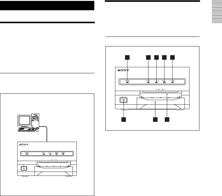
Front Panel
System Configuration
The following shows an example of a printer system configuration.
Computer
Controls the printer operation.
Digital color printer
APOWER indicator
Lights when the POWER switch of the printer is set to ON.
BPRINT indicator (17)
Lights while the printer is printing.
CALARM indicator (17)
Lights in orange in case of paper jamming or occurrence of any other problem.
DRIBBON indicator (17)
Lights when a problem for ink ribbon occurs.
EPAPER indicator (17)
Lights when a problem for paper occurs.
The printer allows you to check the printer operating condition according to the lighting conditions of the PRINT indicator, ALARM indicator, PAPER indicator and RIBBON indicator. For details, see “Indicators on the Front Panel” on page 17.
Started Getting
System Overview / Location and Function of Parts and Controls |
5 |
|
|

Started Getting
FPaper output slot
Printed pages are ejected here.
GPaper tray (7)
Load paper into this tray.
H! POWER switch (12)
Press this switch to turn the printer on or off.
Rear Panel
Supplied Accessories
The printer is packed together with the following accessories. Check that nothing is missing from your package.
Paper Tray (1) |
Stopper (1) |
USB connecting cable (1)
Software Licence Agreement (1)
CD-ROM (1)
Thermal head cleaning cartridge (1)
Before Using this Printer (1)
A (USB) connector (7)
Connects to a computer or another USB peripheral device with a USB cable (supplied).
BTRANSPORT LOCK button (14)
Press this button to secure the internal thermal head when transporting the printer.
C- AC IN connector
Use a proper power cord for your local power supply (not supplied).
Refer to “Warning on power connection” and “Warning on power connection for medical use” on page 2.
D Equipotential ground terminal connector
Used to connect to the equipotential plug to bring the various parts of a system to the same potential. Refer to “Important safeguards/notices for use in the medical environments” on page 2.
Notes
•Retain the original carton and packing materials in case you have to transport the unit in the future.
•Remove the ink ribbon cartridge and paper tray when transporting the printer.
•When transporting the printer, secure the thermal head. (For detailed information on how to secure it, see “Before Transporting the Printer” on page 14.)
6 Supplied Accessories

Assembly
To attach the paper tray
For details of how to load the ink ribbon and paper, see “Loading an Ink Ribbon” on page 9 and “Loading Paper” on page 11.
Paper tray |
Connections
After connecting the USB connecting cable (supplied) to the printer and the computer, connect the power cord. For details about the printer connection, refer to the manuals for the computer or other peripheral devices.
Notes
•Before connecting the printer to the computer, turn off the printer, computer, monitor, and all peripheral devices connected to the computer.
•Before connecting the printer to the computer, disconnect the power cord from the printer. Connect the power cord to the printer only after connecting the printer and the computer.
•The printer is provided with a USB interface that can be connected to any computer equipped with a USB interface.
•Follow the connection procedures described in the computer manual.
•Make sure that the interface cable is connected securely at both ends.
•The printer drive software provided with the printer is not suitable for using the printer connected to a network.
•Operation of the printer is not guaranteed for connection to a USB hub.
USB Port Connection
to |
(USB) connector |
|
USB connecting |
|
cable |
Started Getting
Connections 7
 Loading...