


HCD-RG66
HCD-RG66
AEP Model
UK Model
E Model
Australian model
SERVICE MANUAL
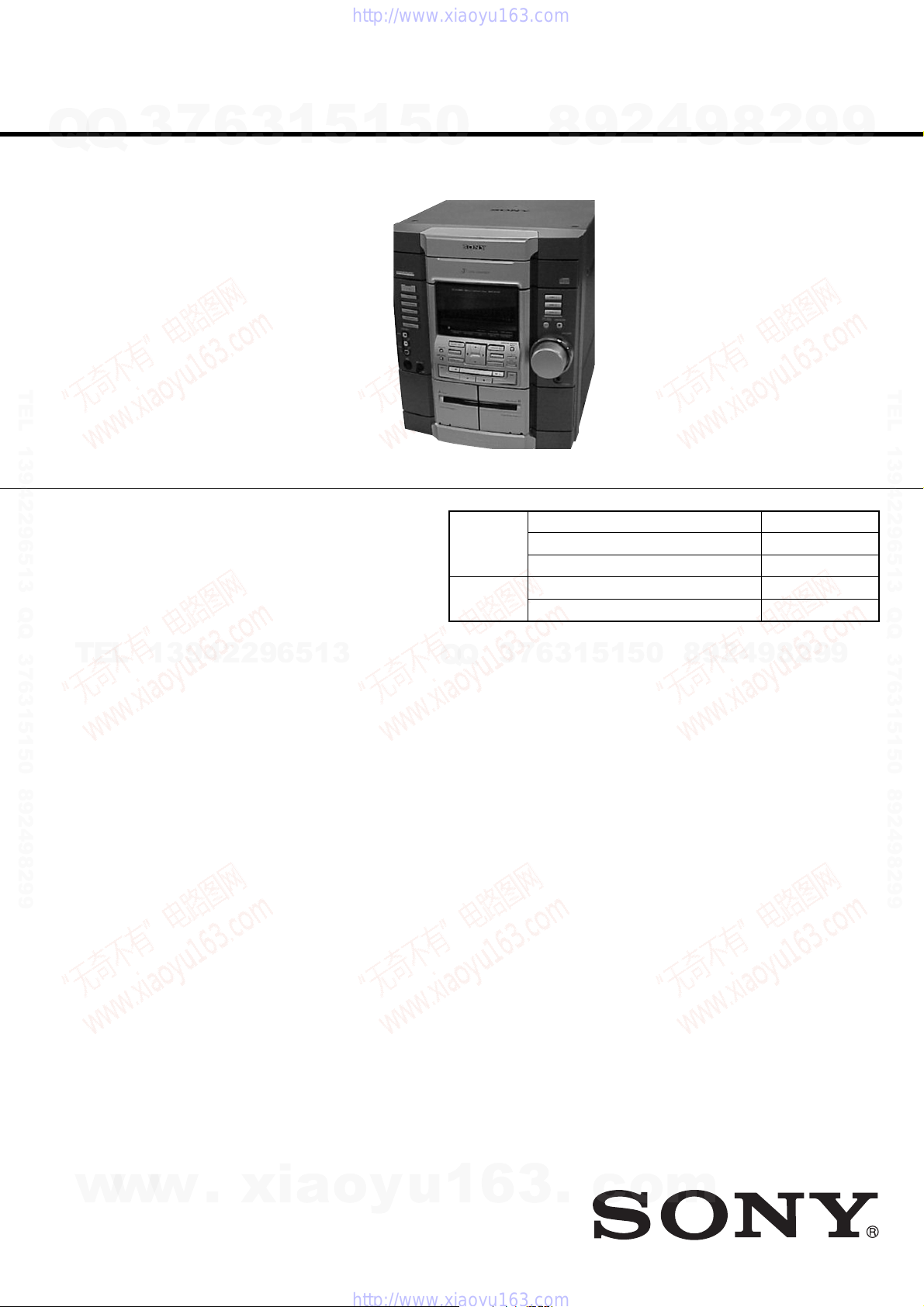
MINI HI-FI COMPONENT SYSTEM
Sony Corporation
Home Audio Company
Published by Sony Engineering Corporation
9-873-972-01
2002D1600-1
© 2002.04
• HCD-RG66 is the tuner, deck, CD and
amplifier section in MHC-RG66.
SPECIFICATIONS
Ver 1.0 2002. 04
Model Name Using Similar Mechanism NEW
CD
CD Mechanism Type CDM58F-K6A
Section
Optical Pick-up Name
KSM-213DCP
Tape deck Model Name Using Similar Mechanism NEW
Section T ape Transport Mechanism T ype CWL43RR-51
Amplifier section
AEP and UK models:
DIN power output (rated) 115 + 115 watts (6 ohms
at 1 kHz, DIN)
Continuous RMS power output (reference)
140 + 140 watts (6 ohms
at 1 kHz, 10% THD)
Music power output (reference)
280 + 280 watts (6 ohms
at 1 kHz, 10% THD)
Singapore and Australian models:
The following measured at AC 120, 220, 230 –
240 V, 50/60 Hz
DIN power output (rated) 115 + 115 watts (6 ohms
at 1 kHz, DIN)
Continuous RMS power output (reference)
140 + 140 watts (6 ohms
at 1 kHz, 10% THD)
Inputs
MD/VIDEO (AUDIO) IN (phono jacks):
voltage 450/250 mV,
impedance 47 kilohms
GAME (AUDIO) IN (phono jack):
voltage 450 mV,
impedance 47 kilohms
MIC (phone jack) (except for European models):
sensitivity 1 mV,
impedance 10 kilohms
Outputs
PHONES (stereo mini jack):
accepts headphones of
8 ohms or more
Front speaker: accepts impedance of 6 to
16 ohms
Surround speaker: accepts impedance of
24 ohms
CD player section
System Compact disc and digital
audio system
Laser Semiconductor laser
(λ =780 nm)
Emission duration:
continuous
Frequency response 2 Hz – 20 kHz (±0.5 dB)
Wavelength 780 – 790 nm
Signal-to-noise ratio More than 90 dB
Dynamic range More than 90 dB
CD OPTICAL DIGITAL OUT
(Square optical connector jack, rear panel)
Wavelength 660 nm
Output Level –18 dBm
Tape deck section
Recording system 4-track 2-channel stereo
Frequency response 50 – 13,000 Hz (±3 dB),
using Sony TYPE I
cassette
Tuner section
FM stereo, FM/AM superheterodyne tuner
FM tuner section
Tuning range 87.5 – 108.0 MHz
Antenna FM lead antenna
Antenna terminals 75 ohm unbalanced
Intermediate frequency 10.7 MHz
AM tuner section
Tuning range
European and Middle Eastern models:
531 – 1,602 kHz (with the
interval set at 9 kHz)
Other models: 531 – 1,602 kHz (with the
interval set at 9 kHz)
530 – 1,710 kHz (with the
interval set at 10 kHz)
Antenna AM loop antenna
Antenna terminals External antenna terminal
Intermediate frequency 450 kHz
General
Power requirements
AEP and UK models: 230 V AC, 50/60 Hz
Australian model: 230 – 240 V AC, 50/
60 Hz
Singapore model: 120 V, 220 V or 230 –
240 V AC, 50/60 Hz
Adjustable with voltage
selector
Power consumption
AEP and UK models: 220 watts
0.5 watts (at the Power
Saving Mode)
Singapore and Australian models:
220 watts
Dimensions (w/h/d) Approx.
280 × 325 × 421 mm
Mass Approx. 10.5 kg
Supplied accessories: AM loop antenna (1)
Remote Commander (1)
Batteries (2)
FM lead antenna (1)
Front speaker pads (8)
Design and specifications are subject to change
without notice.
w
w
w
.
x
i
a
o
y
u
1
6
3
.
c
o
m
Q
Q
3
7
6
3
1
5
1
5
0
9
9
2
8
9
4
2
9
8
T
E
L
1
3
9
4
2
2
9
6
5
1
3
9
9
2
8
9
4
2
9
8
0
5
1
5
1
3
6
7
3
Q
Q
TEL 13942296513 QQ 376315150 892498299
TEL 13942296513 QQ 376315150 892498299
http://www.xiaoyu163.com
http://www.xiaoyu163.com
2
HCD-RG66
1. GENERAL ·········································································· 3
2. DISASSEMBLY ································································ 5
2-1. Case (Top) ····································································· 5
2-2. CD Door········································································ 6
2-3. Front Panel Section·······················································6
2-4. CD Mechanism Deck (CDM58F-K6A)························ 7
2-5. Tape Mechanism Deck (CWL43RR-51) ······················ 7
2-6. MIC Board, PANEL Board, REM Board ····················· 8
2-7. KEYBOARD Board ····················································· 8
2-8. Back Panel Section ······················································· 9
2-9. SUB TRANS Board, VIDEO OUT Board,
SENSOR Board, SURROUND Board·························· 9
2-10. MAIN Board······························································· 10
2-11. POWER Board···························································· 10
2-12. TRANS Board ···························································· 11
2-13. BD Board, DRIVER Board ········································ 11
2-14. SPDL MORTR Board ················································ 12
2-15. Optical Pick-up (KSM-213DCP)································ 12
2-16. MOTOR Board, ADDRESS SENSOR Board ············ 13
2-17. Table (New), Cam (Control) and DC Motor··············· 13
3. TEST MODE ···································································· 14
4. ELECTRICAL ADJUSTMENTS ······························· 16
5. DIAGRAMS······································································ 18
5-1. Circuit Boards Location··············································19
5-1. Circuit Boards Location··············································19
5-2. Block Diagrams –TUNER Section– ··························· 20
MAIN Section····························································· 21
5-3. Printed Wiring Boards – CD Section (1/2) – ·············· 22
5-4. Printed Wiring Boards – CD Section (2/2) – ·············· 23
5-5. Schematic Diagram – CD Section – ··························· 24
5-6. Printed Wiring Board – MAIN Section – ··················· 25
5-7. Schematic Diagram – MAIN Section (1/4) – ············· 26
5-8. Schematic Diagram – MAIN Section (2/4) – ············· 27
5-9. Schematic Diagram – MAIN Section (3/4) – ············· 28
5-10. Schematic Diagram – MAIN Section (4/4) – ············· 29
5-11. Printed Wiring Boards – PANEL Section –················ 30
5-12. Schematic Diagram – PANEL Section – ···················· 31
5-13. Printed Wiring Boards – POWER/TRANS Section – 32
5-14. Schematic Diagram – POWER/TRANS Section –····· 33
5-15. Printed Wiring Board
– SURROUND/KEYBOARD Section – ···················· 34
5-16. Schematic Diagram
– SURROUND/KEYBOARD Section – ···················· 34
5-17. IC PIN FUNCTION DESCRIPTION························· 38
6. EXPLODED VIEWS ······················································ 40
6-1. Main Section ······························································· 40
6-2. Front Panel Section····················································· 41
6-3. MAIN Board Section ·················································· 42
6-4. CD Mechanism Deck Section (CDM58F-K6A)········· 43
7. ELECTRICAL PARTS LIST ······································· 44
SAFETY-RELATED COMPONENT WARNING!!
COMPONENTS IDENTIFIED BY MARK 0 OR DOTTED LINE WITH
MARK 0 ON THE SCHEMATIC DIAGRAMS AND IN THE PARTS
LIST ARE CRITICAL TO SAFE OPERATION. REPLACE THESE
COMPONENTS WITH SONY PARTS WHOSE PART NUMBERS
APPEAR AS SHOWN IN THIS MANUAL OR IN SUPPLEMENTS
PUBLISHED BY SONY.
This appliance is classified as a CLASS 1 LASER product. The
CLASS 1 LASER PRODUCT MARKING is located on the rear
exterior.
Laser component in this product is capable
of emitting radiation exceeding the limit for
Class 1.
CAUTION
Use of controls or adjustments or performance of procedures
other than those specified herein may result in hazardous radiation
exposure.
Notes on chip component replacement
•Never reuse a disconnected chip component.
• Notice that the minus side of a tantalum capacitor may be
damaged by heat.
Flexible Circuit Board Repairing
•Keep the temperature of soldering iron around 270˚C
during repairing.
• Do not touch the soldering iron on the same conductor of the
circuit board (within 3 times).
• Be careful not to apply force on the conductor when soldering
or unsoldering.
NOTES ON HANDLING THE OPTICAL PICK-UP
BLOCK OR BASE UNIT
The laser diode in the optical pick-up block may suffer electrostatic
break-down because of the potential difference generated by the
charged electrostatic load, etc. on clothing and the human body.
During repair, pay attention to electrostatic break-down and also
use the procedure in the printed matter which is included in the
repair parts.
The flexible board is easily damaged and should be handled with
care.
NOTES ON LASER DIODE EMISSION CHECK
The laser beam on this model is concentrated so as to be focused on
the disc reflective surface by the objective lens in the optical pick-
up block. Therefore, when checking the laser diode emission,
observe from more than 30 cm away from the objective lens.
TABLE OF CONTENTS
w
w
w
.
x
i
a
o
y
u
1
6
3
.
c
o
m
Q
Q
3
7
6
3
1
5
1
5
0
9
9
2
8
9
4
2
9
8
T
E
L
1
3
9
4
2
2
9
6
5
1
3
9
9
2
8
9
4
2
9
8
0
5
1
5
1
3
6
7
3
Q
Q
TEL 13942296513 QQ 376315150 892498299
TEL 13942296513 QQ 376315150 892498299
http://www.xiaoyu163.com
http://www.xiaoyu163.com
3
HCD-RG66
This section is extracted
from instruction manual.
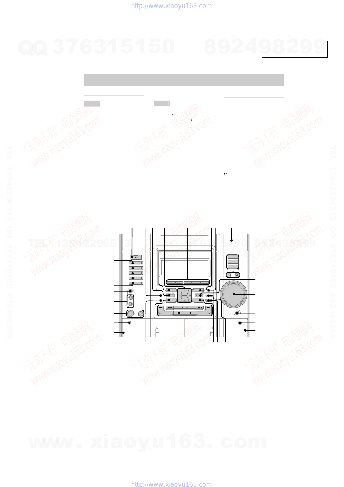
SECTION 1
GENERAL
a
i
n un
it
ALPHABETI
C
AL
O
RDE
R
A –
G
AUDIO
j
acks
h (29)
s (12, 13, 19, 20)
D SYN
C
j (19, 20)
eck A
d (17, 18)
eck B
h (17 – 21, 26)
IRECTION
(18 – 20, 26)
ISC 1 – 3
(12, 13, 20)
ISC SKIP/EX-CHANG
E
a (11,
2)
isc tra
y
(11)
ISPLAY
(17, 24)
(20)
FFECT ON/OFF
(22)
s (11, 13 – 15, 20, 23,
27, 28)
M MODE
(16)
AM
E
k (25)
AME EQ
a (22)
AME MIXING
s (25)
ROOV
E
(22)
–
Z
D (VIDEO)
l (30)
IC
j
ack
*
g (26)
IC LEVE
L
ontrol
*
g (26)
OVIE EQ
(22)
USIC EQ
(22)
FILE
l (23)
HONES
j
ack
f
LAY MOD
E
(12, 13, 20)
EC PAUSE/STAR
T
k (19, 20,
26)
EPEA
T
(12)
PECTRUM
(25)
URROUND SPEAKER
ODE
(21)
APE A/B
; (17, 19)
UNER MEMORY
(14, 15)
/BAND
a (14 – 16, 19)
VIDEO
j
ack
j (29)
VOLUME contro
l
d
BUTT
O
N DE
SC
RIPTI
O
N
S
?/
1
(
p
ower)
/
/
/
OPEN/CLOS
E
a
(deck B)
g
;
;
;
;
;
;
;
(deck A)
f
xce
p
t for Euro
p
ean models
12345 6 78 9
0
qd
qs
qf
qg
qh
qjqkql
qa
w;waws
wd
wf
wg
wj
wh
wk
e;
wl
ea
es
w
w
w
.
x
i
a
o
y
u
1
6
3
.
c
o
m
Q
Q
3
7
6
3
1
5
1
5
0
9
9
2
8
9
4
2
9
8
T
E
L
1
3
9
4
2
2
9
6
5
1
3
9
9
2
8
9
4
2
9
8
0
5
1
5
1
3
6
7
3
Q
Q
TEL 13942296513 QQ 376315150 892498299
TEL 13942296513 QQ 376315150 892498299
http://www.xiaoyu163.com
http://www.xiaoyu163.com
4
HCD-RG66
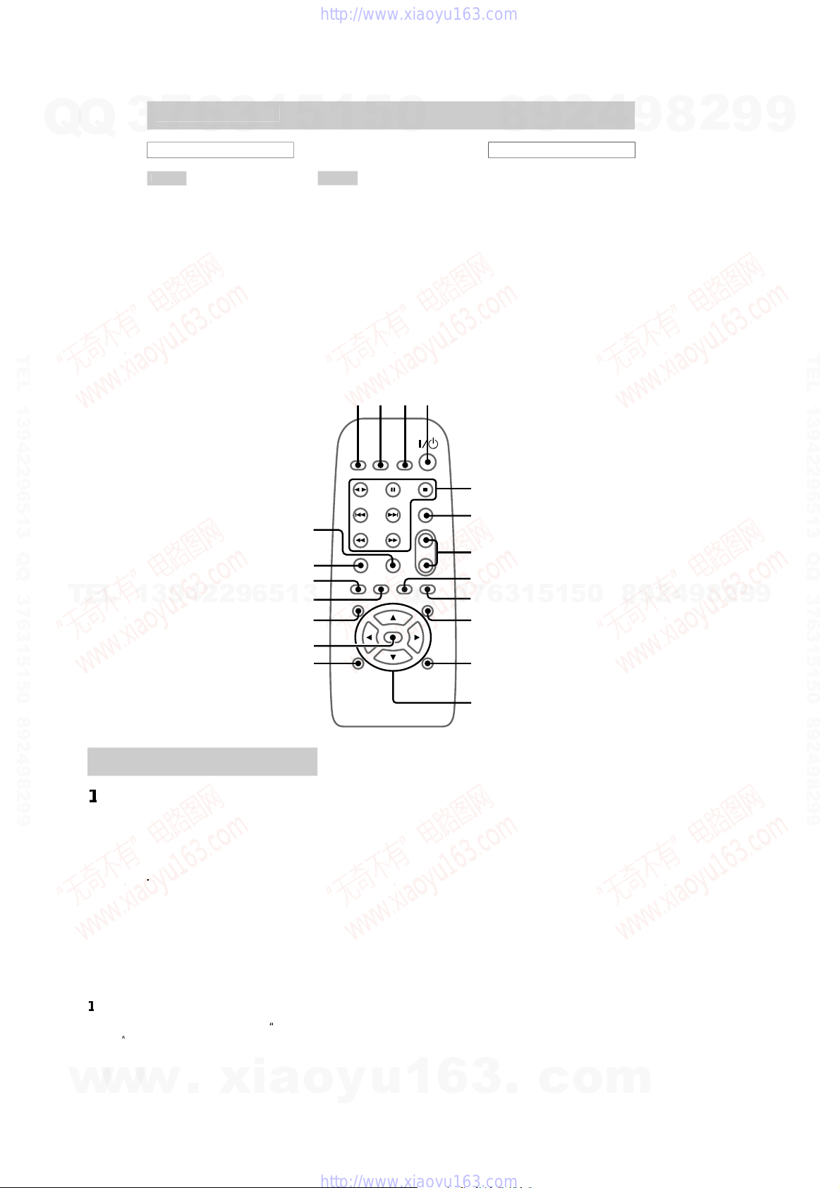
Remote
C
ontro
l
ALPHABETI
C
AL
O
RDE
R
A –
G
j (12, 13, 19, 20)
LEAR
(13)
LOCK/TIMER SELECT
(21, 28)
LOCK/TIMER SET
(11, 20,
27)
.SKI
P
l (12)
FFECT ON/OFF
a (22)
f (11, 13 – 15, 20, 23,
27, 28)
AM
E
k (25)
–
Z
D (VIDEO)
(30)
FILE
d (23)
RESET +/–
(14 – 16)
RESET EQ
g (22)
LEE
P
(27)
URROUN
D
(23)
APE A/B
(17, 19)
UNER/BAN
D
h (14 – 16, 19)
UNING +/–
(14 – 16)
VOL +/–
BUTT
O
N DE
SC
RIPTI
O
N
S
?/
1
(
p
ower)
/
/
/
s
5
6
7
8
9
0
qa
qs
12 34
qd
qf
qg
qh
ql
qk
qj
etting the cloc
k
P
r
ess
?/
1
to turn on t
h
e s
y
stem
.
Press
C
L
OC
K
/
TIMER
S
ET on th
e
m
o
t
e.
r
ess
or
repeate
dly
to set t
h
e
h
our
.
r
ess
he minute indication flashes
.
r
ess
or
repeate
dly
to set t
he
m
i
n
u
t
e.
r
ess
ENTER.
he clock starts workin
g.
To ad
j
ust the cloc
k
ress
CLOCK
/
TIMER
SET
on t
h
e remote
.
r
ess
or
re
p
eate
dly
to se
l
ect
, t
h
en
p
ress
ENTER.
o t
h
e same
p
roce
d
ures as ste
p
3 to 6
v
e.
ot
e
he clock settin
g
s are canceled when
y
ou disconnec
t
the
p
ower cord or if a
p
ower failure occurs
.
w
w
w
.
x
i
a
o
y
u
1
6
3
.
c
o
m
Q
Q
3
7
6
3
1
5
1
5
0
9
9
2
8
9
4
2
9
8
T
E
L
1
3
9
4
2
2
9
6
5
1
3
9
9
2
8
9
4
2
9
8
0
5
1
5
1
3
6
7
3
Q
Q
TEL 13942296513 QQ 376315150 892498299
TEL 13942296513 QQ 376315150 892498299
http://www.xiaoyu163.com
http://www.xiaoyu163.com
5
HCD-RG66
SECTION 2
DISASSEMBLY
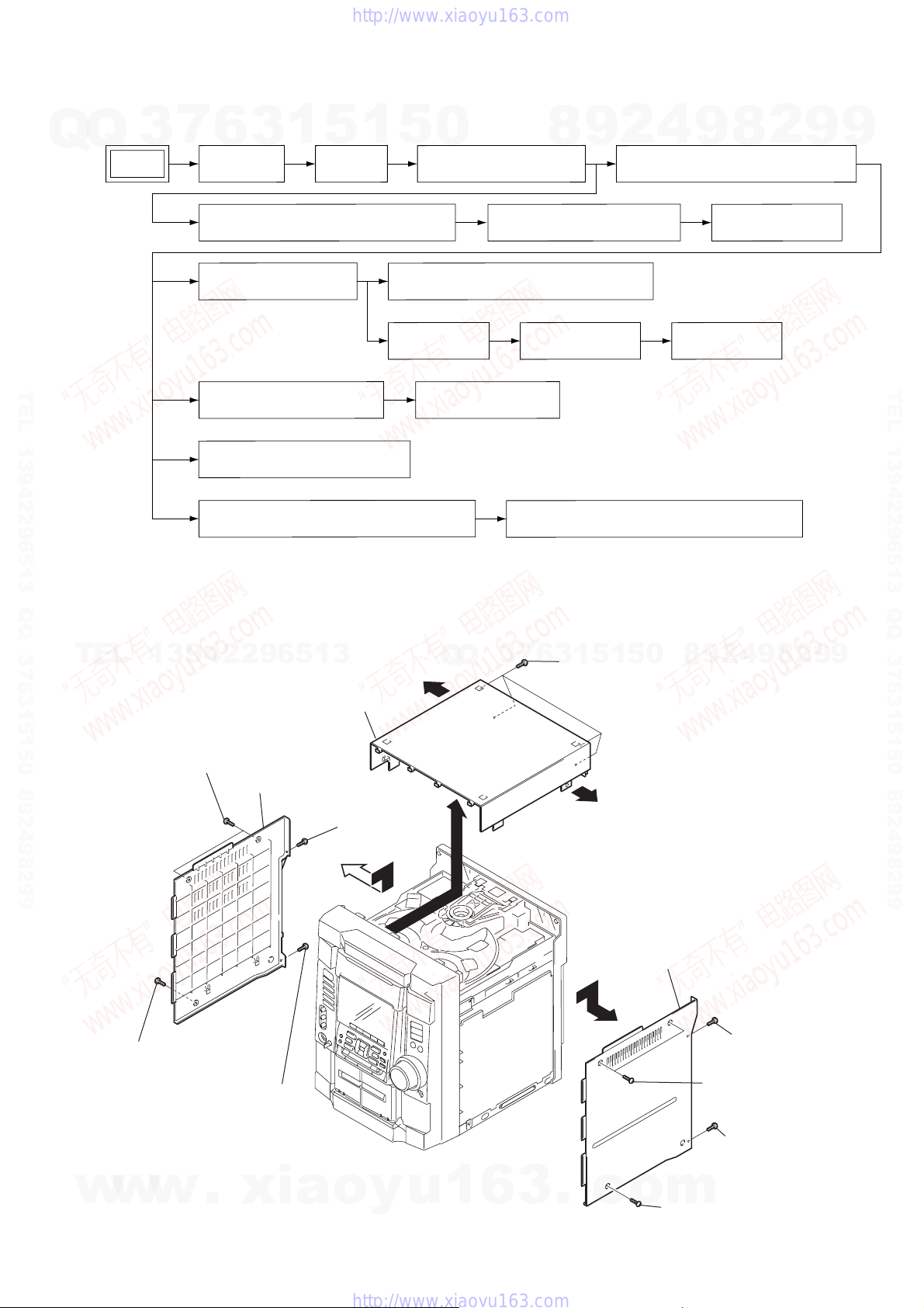
Note : Disassemble the unit in the order as shown below.
Note : Follow the disassembly procedure in the numerical order given.
2-1. Case (Top)
CD DOOR CD MECHANISM DECK (CDM58F-K6A)CASE (TOP) FRONT PANEL SECTION
BACK PANEL SECTION
KEYBOARD BOARD
MIC BOARD, PANEL BOARD,
REM BOARD
TAPE MECHANISM DECK (CWL43RR-51)
MOTOR BOARD,
ADDRESS SENSOR
BOARD
SET
OPTICAL PICK-UP (KSM-213DCP)
TRANS BOARD
SUB TRANS BOARD, VIDEO OUT BOARD,
SENSOR BOARD, SURROUND BOARD
POWER BOARD
SPDL MOTOR BOARD
MAIN BOARD
BD BOARD, DRIVER BOARD
TABLE (NEW),CAM (CONTROL) AND DC MOTOR
case (Side-R)
case (Side-L)
5
qd
qs
qs
q;
qf
case (Top)
6
two screws (Case 3 TP2)
8
screw
(+BVTT 3
×
8)
3
screw
(+BVTT 3
×
8)
9
screw
(+BVTT 3
×
8)
4
screw
(+BVTT 3
×
8)
1
two screws
(Case 3 TP2)
qa
four screws (+BVTP 3
×
10)
7
screw (Case 3 TP2)
2
screw (Case 3 TP2)
w
w
w
.
x
i
a
o
y
u
1
6
3
.
c
o
m
Q
Q
3
7
6
3
1
5
1
5
0
9
9
2
8
9
4
2
9
8
T
E
L
1
3
9
4
2
2
9
6
5
1
3
9
9
2
8
9
4
2
9
8
0
5
1
5
1
3
6
7
3
Q
Q
TEL 13942296513 QQ 376315150 892498299
TEL 13942296513 QQ 376315150 892498299
http://www.xiaoyu163.com
http://www.xiaoyu163.com
6
HCD-RG66
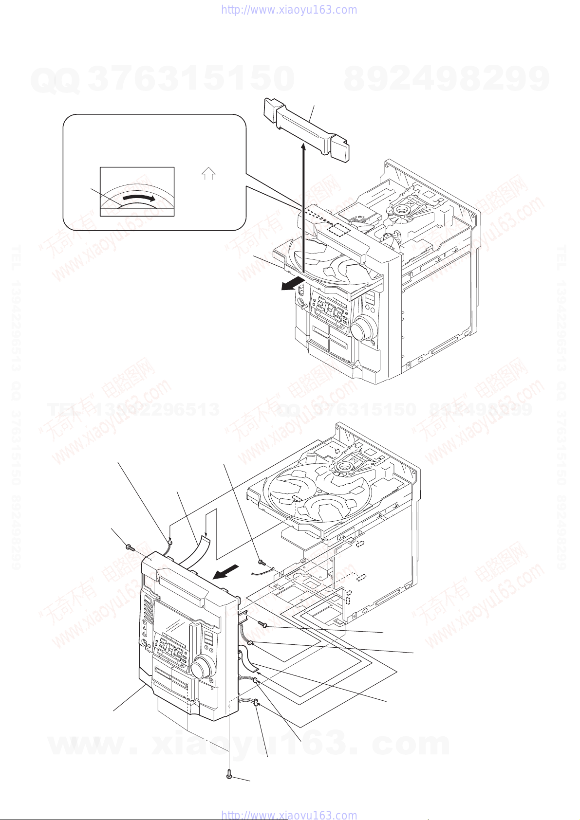
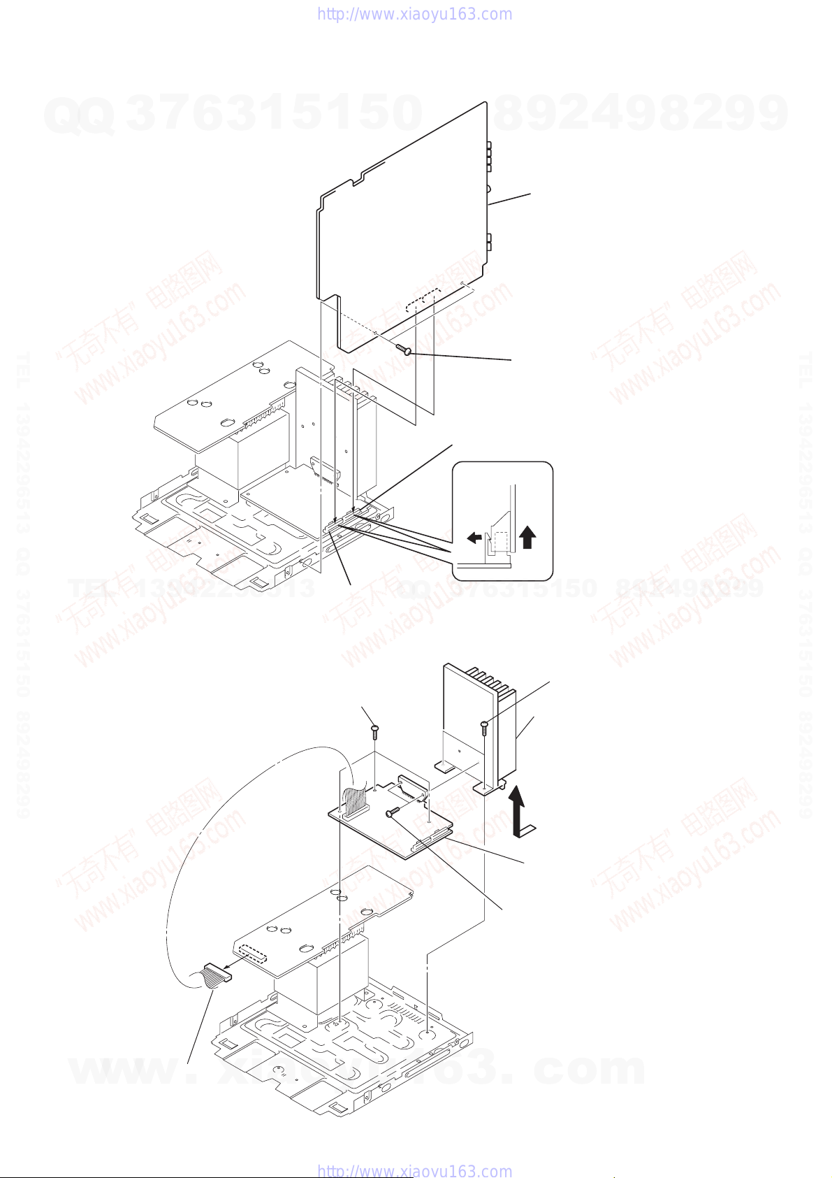
2-2. CD Door
2-3. Front Panel Section
2
Pull-out the disc tray.
1
Turn the pulley to the direction of arrow.
pulley
4
CD door
Front panel side
CD mechanism deck (CDM58F-K6A)
3
1
three screws (+BVTT 3
×
6)
9
wire (flat type) 13p (CN302)
7
wire (flat type)
19p (CN733)
qa
connector 7p (CN202)
qs
front panel
0
connector 3p (CN201)
8
connector 8p (CN305
)
6
connector 2p (CN605)
3
screw (+BVTP 3
×
10)
4
screw (+BVTP 3
×
10)
2
screw (+BVTP 3
×
10)
5
w
w
w
.
x
i
a
o
y
u
1
6
3
.
c
o
m
Q
Q
3
7
6
3
1
5
1
5
0
9
9
2
8
9
4
2
9
8
T
E
L
1
3
9
4
2
2
9
6
5
1
3
9
9
2
8
9
4
2
9
8
0
5
1
5
1
3
6
7
3
Q
Q
TEL 13942296513 QQ 376315150 892498299
TEL 13942296513 QQ 376315150 892498299
http://www.xiaoyu163.com
http://www.xiaoyu163.com
7
HCD-RG66
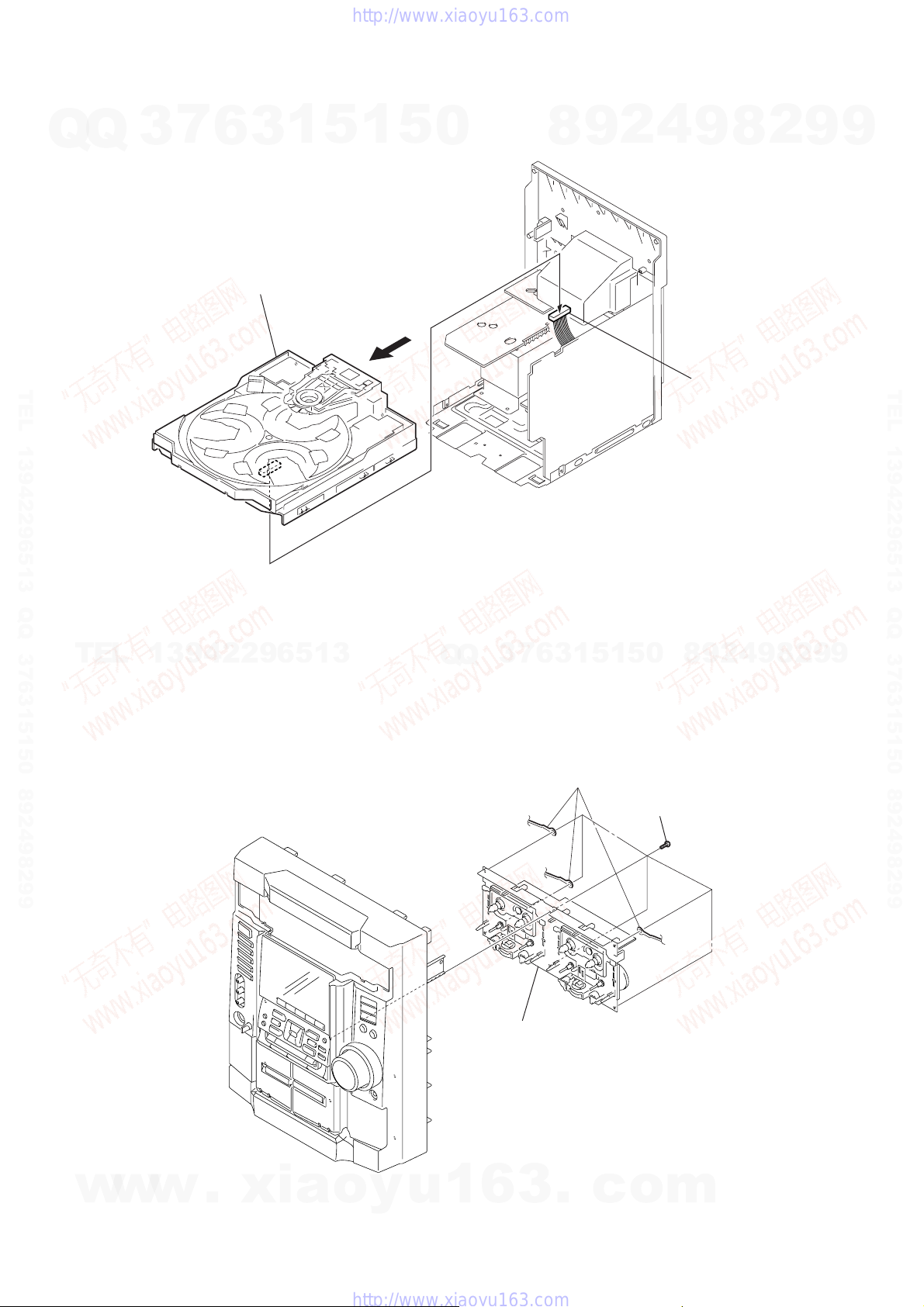
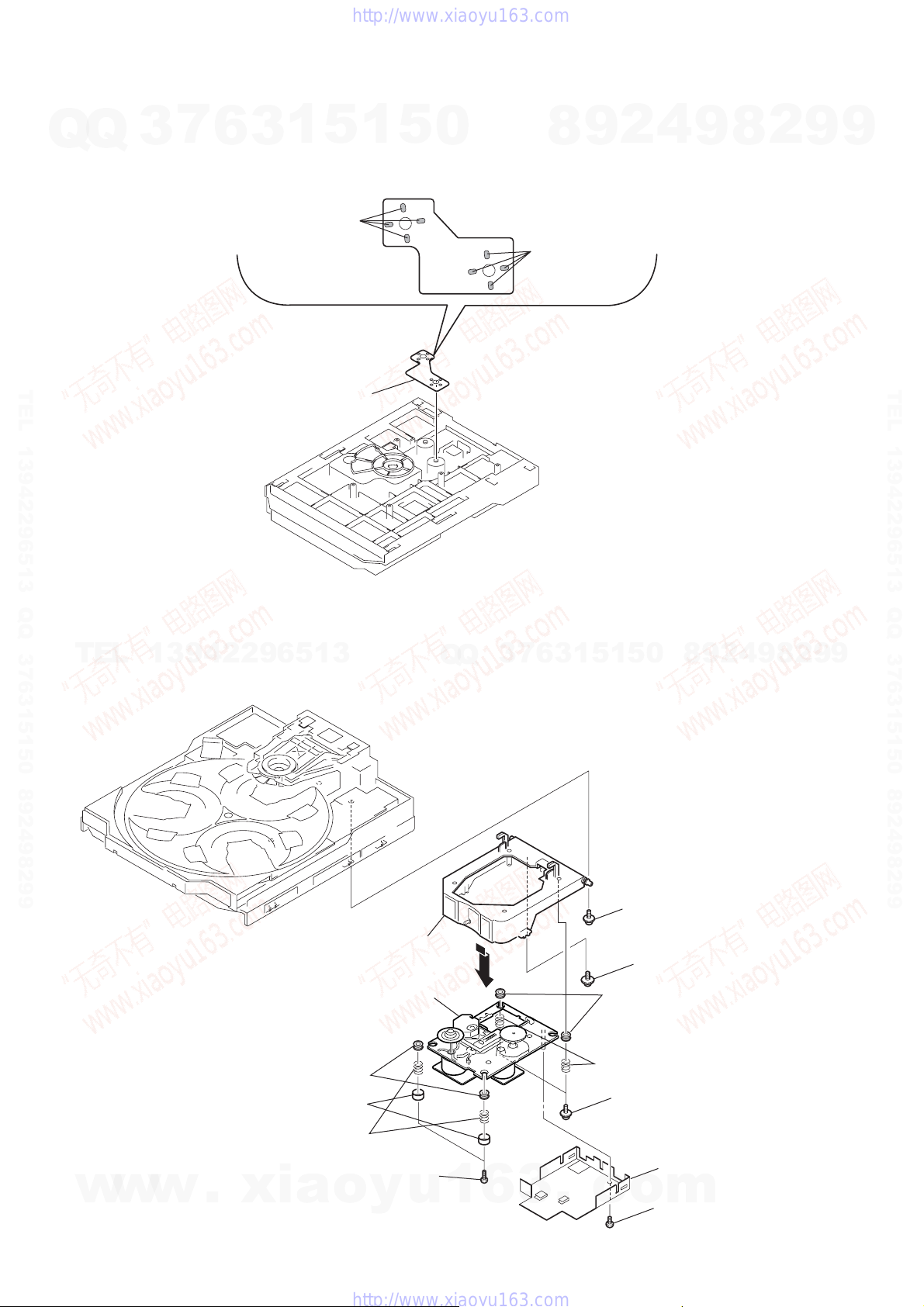
2-4. CD Mechanism Deck (CDM58F-K6A)
2-5. Tape Mechanism Deck (CWL43RR-51)
1
connector 8p (CN734
)
3
CD mechanism deck (CDM58F-K6A)
2
1
six
screws
(+PTPWH M2.6
)
2
three ground wires
3
tape mechanism deck
(CWL43RR-51)
w
w
w
.
x
i
a
o
y
u
1
6
3
.
c
o
m
Q
Q
3
7
6
3
1
5
1
5
0
9
9
2
8
9
4
2
9
8
T
E
L
1
3
9
4
2
2
9
6
5
1
3
9
9
2
8
9
4
2
9
8
0
5
1
5
1
3
6
7
3
Q
Q
TEL 13942296513 QQ 376315150 892498299
TEL 13942296513 QQ 376315150 892498299
http://www.xiaoyu163.com
http://www.xiaoyu163.com
8
HCD-RG66
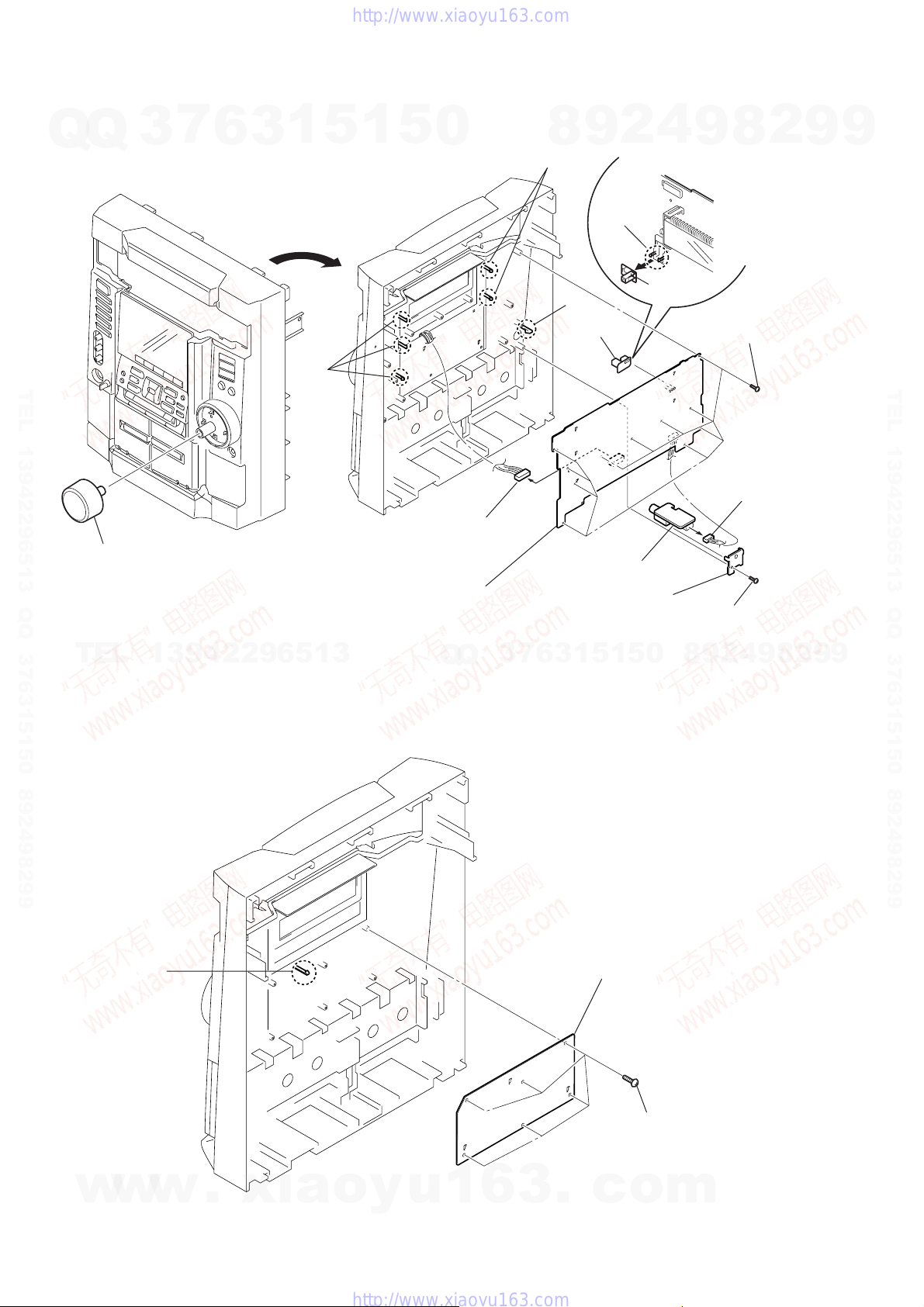
2-6. MIC Board, PANEL Board, REM Board
2-7. KEYBOARD Board
9
connector
7p (CN661)
5
connector
3p (CN663)
three
claws
claw
two claws
two claws
8
PANEL board
4
mic bracket
6
MIC board
q;
REM
board
REM
board
1
volume knob
2
7
eleven
screws
(+PTPWH M2.6
)
3
screw
(+PTPWH M2.6)
2
KEYBOARD board
claw
1 six
screws
(+PTPWH M2.6)
w
w
w
.
x
i
a
o
y
u
1
6
3
.
c
o
m
Q
Q
3
7
6
3
1
5
1
5
0
9
9
2
8
9
4
2
9
8
T
E
L
1
3
9
4
2
2
9
6
5
1
3
9
9
2
8
9
4
2
9
8
0
5
1
5
1
3
6
7
3
Q
Q
TEL 13942296513 QQ 376315150 892498299
TEL 13942296513 QQ 376315150 892498299
http://www.xiaoyu163.com
http://www.xiaoyu163.com

9
HCD-RG66
2-8. Back Panel Section
2-9. SUB TRANS Board, VIDEO OUT Board, SENSOR Board, SURROUND Board
6
connector
3p (CN903)
8
connector 2p (CN504)
(from POWER board)
5
connector
(CN2)
7
connector
3p (CN310)
9
connector
2p (CN303)
q;
2 three
screws
(+BVTP 3
×
10)
3
screw
(+BVTP 3
×
10)
4
screw
( +BVTP 3
×
10
)
1 two
screws
(+BVTT 3
×
6)
qa back panel
5 two
screws (+BVTP 3
×
10)
9 two
screws (+BVTP 3
×
10)
qa two
screws (+BVTP 3
×
10)
1 two
screws (+BVTP 3
×
10)
7
screw (+PTPWH M2.6)
3
screw (+BVTP 3
×
10)
2 SUB TRANS board
q; SURROUND board
4 VIDEO OUT board
6 cover (duct)
8 SENSOR board
qs fan dc
w
w
w
.
x
i
a
o
y
u
1
6
3
.
c
o
m
Q
Q
3
7
6
3
1
5
1
5
0
9
9
2
8
9
4
2
9
8
T
E
L
1
3
9
4
2
2
9
6
5
1
3
9
9
2
8
9
4
2
9
8
0
5
1
5
1
3
6
7
3
Q
Q
TEL 13942296513 QQ 376315150 892498299
TEL 13942296513 QQ 376315150 892498299
http://www.xiaoyu163.com
http://www.xiaoyu163.com
10
HCD-RG66
2-10. MAIN Board
2-11. POWER Board
3
connector 13p (CN502)
2
connector 13p (CN503)
MAIN board
1
two
screws (+BVTT 3
×
6
)
4
MAIN board
2
three screws (+BVTT 3
×
6)
6
5
two screws (+BVTT 3
×
6
)
7
heat sink
3
two screws (+BVTP 3
× 1
6)
4 POWER
board
1
connector 13p (CN915)
w
w
w
.
x
i
a
o
y
u
1
6
3
.
c
o
m
Q
Q
3
7
6
3
1
5
1
5
0
9
9
2
8
9
4
2
9
8
T
E
L
1
3
9
4
2
2
9
6
5
1
3
9
9
2
8
9
4
2
9
8
0
5
1
5
1
3
6
7
3
Q
Q
TEL 13942296513 QQ 376315150 892498299
TEL 13942296513 QQ 376315150 892498299
http://www.xiaoyu163.com
http://www.xiaoyu163.com

11
HCD-RG66
2-12. TRANS Board
2-13. BD Board, DRIVER Board
1 two
screws (+BVTT 4
×
6)
2 two
screws (+BVTT 4
×
6)
3 TRANS board
4
four
screws (+BTTP M2.6
)
5
2
wire (flat type)
16p (CN731)
8
wire (flat type)
8p (CN702)
9
DRIVER board
6
BD board
7
screw (+BTTP M2.6
)
1
connector 10p (CN735)
3
connector
6p (CN732)
w
w
w
.
x
i
a
o
y
u
1
6
3
.
c
o
m
Q
Q
3
7
6
3
1
5
1
5
0
9
9
2
8
9
4
2
9
8
T
E
L
1
3
9
4
2
2
9
6
5
1
3
9
9
2
8
9
4
2
9
8
0
5
1
5
1
3
6
7
3
Q
Q
TEL 13942296513 QQ 376315150 892498299
TEL 13942296513 QQ 376315150 892498299
http://www.xiaoyu163.com
http://www.xiaoyu163.com
12
HCD-RG66
2-14. SPDL MORTR Board
2-15. Optical Pick-up (KSM-213DCP)
1 Remove solders.
(four places)
2 Remove solders.
(four places)
3 SPDL MOTOR board
qs
optical pick-up
(KSM-213DCP)
qa
8 two
screws (+PTPWH M2.6
)
9 two spring
(insulator), coils
2 CD
(cover) (down)
7 two spring
(insulator), coils
3
screw (+PTPWH M2.6)
q;
screw (DIA. 12)
5
two screws (+BTTP M2.6)
1
screw (+BTTP M2.6)
qf
two insulators
4
holder (BU) assy
qd
two insulators
6
two stoppers (BU)
w
w
w
.
x
i
a
o
y
u
1
6
3
.
c
o
m
Q
Q
3
7
6
3
1
5
1
5
0
9
9
2
8
9
4
2
9
8
T
E
L
1
3
9
4
2
2
9
6
5
1
3
9
9
2
8
9
4
2
9
8
0
5
1
5
1
3
6
7
3
Q
Q
TEL 13942296513 QQ 376315150 892498299
TEL 13942296513 QQ 376315150 892498299
http://www.xiaoyu163.com
http://www.xiaoyu163.com
13
HCD-RG66
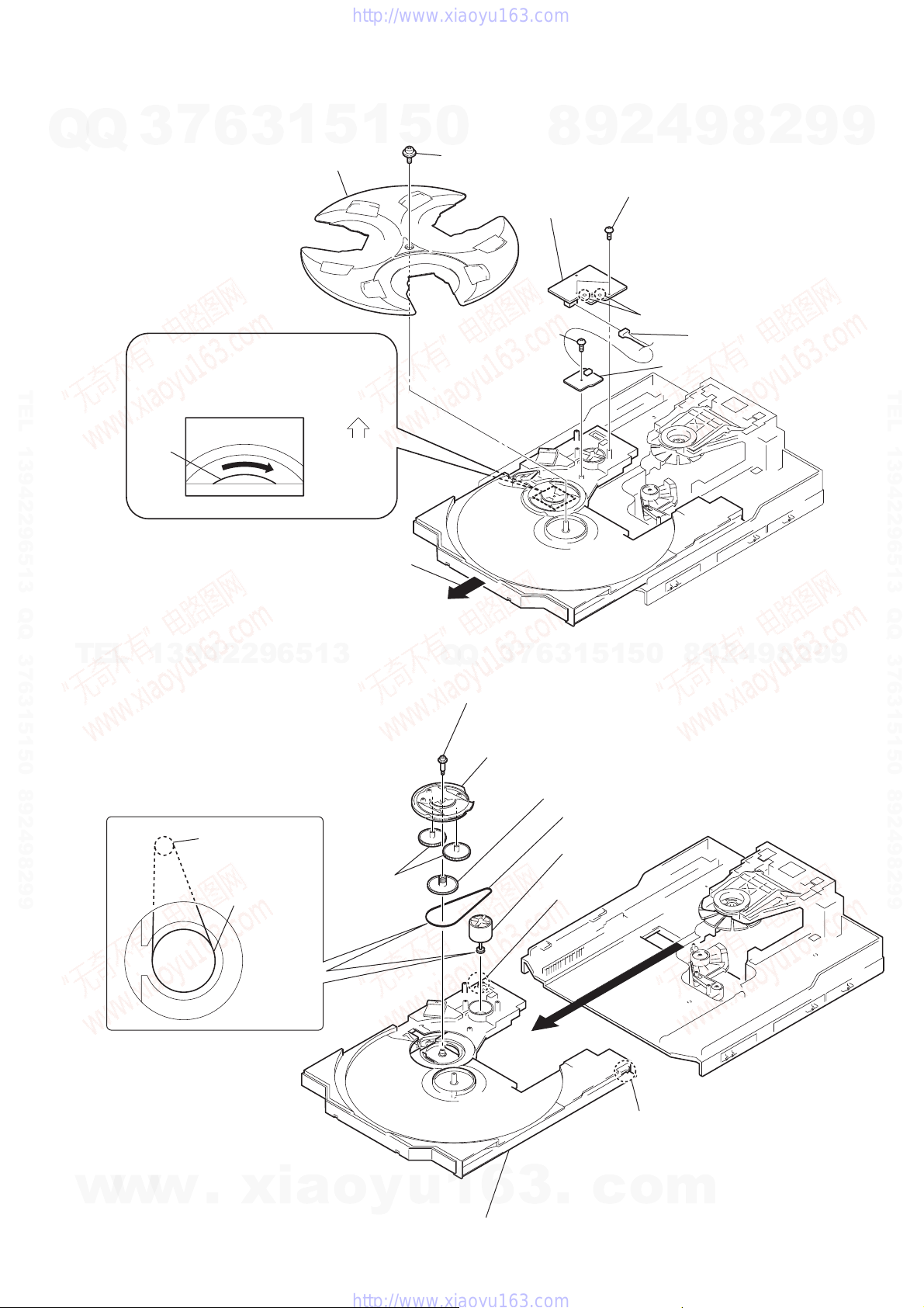
2-16. MOTOR Board, ADDRESS SENSOR Board
2-17. Table (New), Cam (Control) and DC Motor
2
Pull out the disc tray.
6
two
screws (+BTTP M2.6)
3
screw (+PTPWH 2.6
×
8)
4
tray
9
screw (+BTTP M2.6)
8
MOTOR board
q;
ADDRESS SENSOR board
7
Remove the two solderings of motor.
5
connector 4p (CN722)
1
Turn the pulley to the direction of arrow.
pulley
Front panel side
CD mechanism deck (CDM58F-K6A)
*Cautions of an assembly
7 DC
motor (TURN)
claw
claw
6 belt
5 pulley (S)
4 gear (U)
2 screw (STEP)
3 cam (CONTROL)
1 table (NEW)
DC
motor (TURN)
pulley (S)
w
w
w
.
x
i
a
o
y
u
1
6
3
.
c
o
m
Q
Q
3
7
6
3
1
5
1
5
0
9
9
2
8
9
4
2
9
8
T
E
L
1
3
9
4
2
2
9
6
5
1
3
9
9
2
8
9
4
2
9
8
0
5
1
5
1
3
6
7
3
Q
Q
TEL 13942296513 QQ 376315150 892498299
TEL 13942296513 QQ 376315150 892498299
http://www.xiaoyu163.com
http://www.xiaoyu163.com
14
HCD-RG66
SECTION 3
TEST MODE
[Cold Reset]
• The cold reset clears all data including preset data stored in the
RAM to initial conditions. Execute this mode when returning
the set to the customer.
Procedure:
1. Press three buttons x , ENTER , and ?/1 simultaneously.
2. The fluorescent indicator tube displays “COLD RESET” and
the set is reset.
[Aging Mode]
This mode can be used for operation check of CD section and tape
deck section.
• If an error occurred:
The aging operation stops and is displayed status.
• If no error occurs:
The aging operation continues repeatedly.
1. Operating method of Aging Mode
Turn on the main power and select “CD” of the function.
1) Set three discs in tray. Select ALL DISCS, and REPEAT OFF.
2) Load the tapes recording use into both decks.
3) Press three buttons x , GAME EQ , and
DISC SKIP/EX-CHANGE simultaneously.
4) Aging operations of CD and tape are started at the same time.
5) To exit the aging mode, perform [Cold Reset].
2. Aging mode in CD section
1) Operation during aging mode
• In the a gining mode ,the program is excuted in the following
sequence.
(1) The disc tray opens and closes.
(2) The disc tray turns to select a disc 3.
(3) The pick-up accesses to the first track, and plays 3 seconds.
(4) The pick-up accesses to the last track, and plays 3 seconds.
(5) The disc tray opens and closes.
(6) The disc tray turns to select a disc 1.
(7) The same operation starts like step (3).
(8) After a disc 1 aging operation, a disc 2 is selected.
(9) When an aging operation of a disc 3 is completed, the display
“AGING
∗∗∗∗” value increases.
(10) If no error occurs, the aging operation continues repeatedly.
2) Error display
Step
1
2
3
4
5
6
7
Operation
Rewind the TAPE A
Rewind the TAPE B
Play the TAPE A (1 minute)
Stop the TAPE A (1 second)
Play the TAPE A (3 minutes)
Rewind(AMS) the TAPE A
F.F.(AMS) the TAPE A
Display
TAPE AAG-01
TAPE BAG-01
TAPE AAG-02
TAPE AAG-03
TAPE AAG-04
TAPE AAG-05
TAPE AAG-06
Disc error
Display Error
E00D01022 Focus error (No disc)
E00D02022 Sub Q error (Focus is good)
E00D02023 TOC reading error
E00D02014 Access error (Unable within regular time)
Mechanism error
Display Error
E00M__E_0 Error during opening tray
E00M__C_2 EX-CHANGE disc error
E00M__D_0 Error during closing tray
E00M__F_3 EX-OPEN error
E00M__D_5 EX-CLOSE error
E00M__C_2 Chuck-up error
E00M__C_3 Unchucking error
3. Aging mode in Tape Deck section
1) Operation during aging mode
• In the agining mode, the program is excuted in the following
sequence.
2) Error display
• If error occurred, the display remains like “TAPE BAG-2”.
4. Exiting from the aging mode
• Be sure to perform Cold Reset to exit from the aging mode.
[GC Test Mode]
• All fluorescent segments and LEDs are tested.
•Keyboard check.
Procedure:
1. Press the ?/1 button to turn the set ON.
2. To enter the test mode, press the three buttons x , GAME EQ
and DISC 2 simultaneously.
3. All segments and LEDs are turned on.
4. Press the GAME EQ and DISC 2 buttons simultaneously, and
the key check mode is activated.
5. The message “KEY 0 0 0 ” is displayed.
Each time a button is pressed, the key code number is displayed.
6. Press the GAME EQ and DISC 2 buttons simultaneously, and
the key count mode is activated.
7. The message “KEYCNT 0 1” is displayed.
Each time a button is pressed, “KEYCNT 0 1” value increased.
However, once a button is pressed, it is no longer taken into
account.
8. Press the GAME EQ and DISC 2 buttons simultaneously, and
the head phone detect mode is activated.
9. The message “H_P OFF” is displayed when a headphone jack
is not inserted.
“H_P ON ” is displayed when a headphone jack is inserted.
10. Press the GAME EQ and DISC 2 buttons simultaneously, and
the volume control detect mode is activated.
11. The message “VOLUME FLAT” is displayed.
“VOLUME UP” is displayed if rotating VOLUME knob
clockwise, or “VOLUME DOWN” is displayed if rotating
counterclockwise.
12. To exit from the GC test mode after the volume control detect
mode, press the GAME EQ and DISC 2 buttons simultaneously .
w
w
w
.
x
i
a
o
y
u
1
6
3
.
c
o
m
Q
Q
3
7
6
3
1
5
1
5
0
9
9
2
8
9
4
2
9
8
T
E
L
1
3
9
4
2
2
9
6
5
1
3
9
9
2
8
9
4
2
9
8
0
5
1
5
1
3
6
7
3
Q
Q
TEL 13942296513 QQ 376315150 892498299
TEL 13942296513 QQ 376315150 892498299
http://www.xiaoyu163.com
http://www.xiaoyu163.com
15
HCD-RG66
[Version and Destination Display Mode]
•The version or destination is displayed.
Procedure:
1. Press the ?/1 button to turn the set ON.
2. To enter the test mode, press the three buttons x , GAME EQ
and MOVIE EQ simultaneously.
3. The destination is displayed.
4. Press the x and ENTER buttons simultaneously.
5. The version is displayed.
6. To exit from this mode, press the ?/1 button to turn the set
OFF.
[CD Service Mode]
•This mode can run the CD sled motor freely. Use this mode, for
instance, when cleaning the pick-up.
Procedure:
1. Press the ?/1 button to turn the set ON.
2. Select the function “CD”.
3. To enter the test mode, press three buttons x , GAME EQ ,
and OPEN/CLOSE simultaneously.
4. The message “CD S” is displayed. The CD service mode is
selected.
5. With the CD in stop status, press the M + button to mov e the
pick-up to outside track and “CD S -F” is displayed, or press
the – m button to inside track and “CD S -R” is displayed.
6. To exit from this mode, perform as follows:
1) Move the pick-up to the most inside track.
2) Perform Cold Reset.
Note: • Always move the pick-up to most inside track when exiting from
this mode. Otherwise, a disc will not be unloaded.
• Do not run the sled motor excessively , otherwise the gear can be
chipped.
[MC Test Mode]
•This mode is used to test the function of the equalizer.
Procedure:
1. Press the ?/1 button to turn the set ON.
2. To enter the test mode, press the three buttons x , GAME EQ
and DISC 3 simultaneously.
3. Press the MOVIE EQ button.
The function of the equalizer is set to “GEQ MIN”.
4. Press the MUSIC EQ button.
The function of the equalizer is set to “GEQ MAX”.
5. Press the P FILE button.
The function of the equalizer is set to “GEQ FLAT”.
6. To exit from this mode, press the ?/1 button to turn the set
OFF.
[CD Ship Mode (No Memory Clear) ]
•This mode moves the pick-up to the position durable to vibra-
tion. Use this mode when returning the set to the customer after
repair.
Procedure:
1. Press the ?/1 button to turn the set ON.
2. Select the function “CD”.
3. Press the ?/1 button to turn the set OFF.
4. Press the CD button and ?/1 button simultaneously.
5. The "STANDBY" display blinks instantaneously , then “LOCK”
is displayed and the CD ship mode is set.
w
w
w
.
x
i
a
o
y
u
1
6
3
.
c
o
m
Q
Q
3
7
6
3
1
5
1
5
0
9
9
2
8
9
4
2
9
8
T
E
L
1
3
9
4
2
2
9
6
5
1
3
9
9
2
8
9
4
2
9
8
0
5
1
5
1
3
6
7
3
Q
Q
TEL 13942296513 QQ 376315150 892498299
TEL 13942296513 QQ 376315150 892498299
http://www.xiaoyu163.com
http://www.xiaoyu163.com
16
HCD-RG66
SECTION 4
ELECTRICAL ADJUSTMENTS
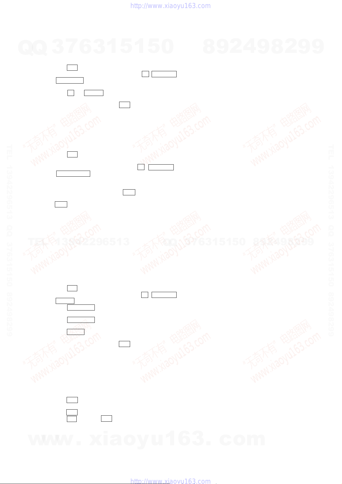
FM Tuned Level Adjustment
Procedure:
1. Supply a 98 MHz signal at 28 dB from the ANTENN A terminal.
2. Tune the set to 98 MHz.
3. Adjust RV101 to the point (moment) when the TUNED
indicator will change from going off to going on.
Adjustment Location: MAIN board
Null Adjustment
Procedure:
1. Supply a 98 MHz signal at 60 dB from the ANTENN A terminal.
2. Tune the set to 98 MHz.
3. Measure voltage between pin 21 and pin 23 of IC 101. Adjust
T101 until the voltage becomes 0 V.
Adjustment Location: MAIN board
[MAIN BOARD] Component side
FM RF Signal generator
75
Ω
coaxial
Carrier frequency : 98 MHz
Modulation : AUDIO 1 kHz, 75 kHz
deviation (100%)
Output level : 30 dB (at 75
Ω
open)
FM ANTENNA terminal
(JK101)
set
FM RF Signal generator
75
Ω
coaxial
Carrier frequency : 98 MHz
Modulation : AUDIO 1 kHz, 75 kHz
deviation (100%)
Output level : 60 dB (at 75
Ω
open)
FM ANTENNA terminal
(JK101)
set
T101: NULL
IFT101: AM IF
RV101:
FM TUNED LEVEL
AM RF Signal generator
30% amplitude
modulation by
400Hz signal
output level : as low as possible
AM ANTENNA termina
l
(JK101)
set
AM IF Adjustment
TUNER SECTION
Procedure:
1. Set the frequency of the AM RF signal generator to 1000 kHz
(at 10 kHz step) or 999 kHz (at 9 kHz step).
2. Tune the set to AM 1000 kHz (at 10 kHz step) or 999 kHz (at 9
kHz step).
3. Adjust IFT101 so that the reading on level meter becomes in
maximum.
headphones jack (JK801)
level mete
r
set
16
Ω
w
w
w
.
x
i
a
o
y
u
1
6
3
.
c
o
m
Q
Q
3
7
6
3
1
5
1
5
0
9
9
2
8
9
4
2
9
8
T
E
L
1
3
9
4
2
2
9
6
5
1
3
9
9
2
8
9
4
2
9
8
0
5
1
5
1
3
6
7
3
Q
Q
TEL 13942296513 QQ 376315150 892498299
TEL 13942296513 QQ 376315150 892498299
http://www.xiaoyu163.com
http://www.xiaoyu163.com
17
HCD-RG66
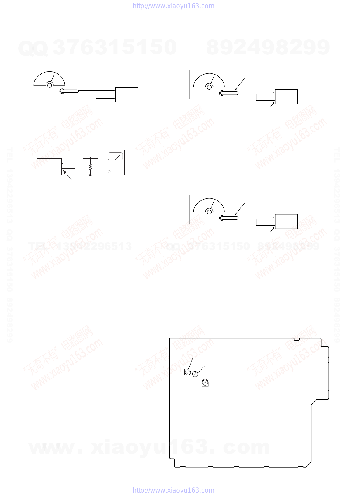
CN731
TP731:
TP connected to pin
q;
(IC751)
IC751
CN733
IC731
Adjustment Location: BD board
[BD BOARD] (Component Side)
CD SECTION
RF Level Check
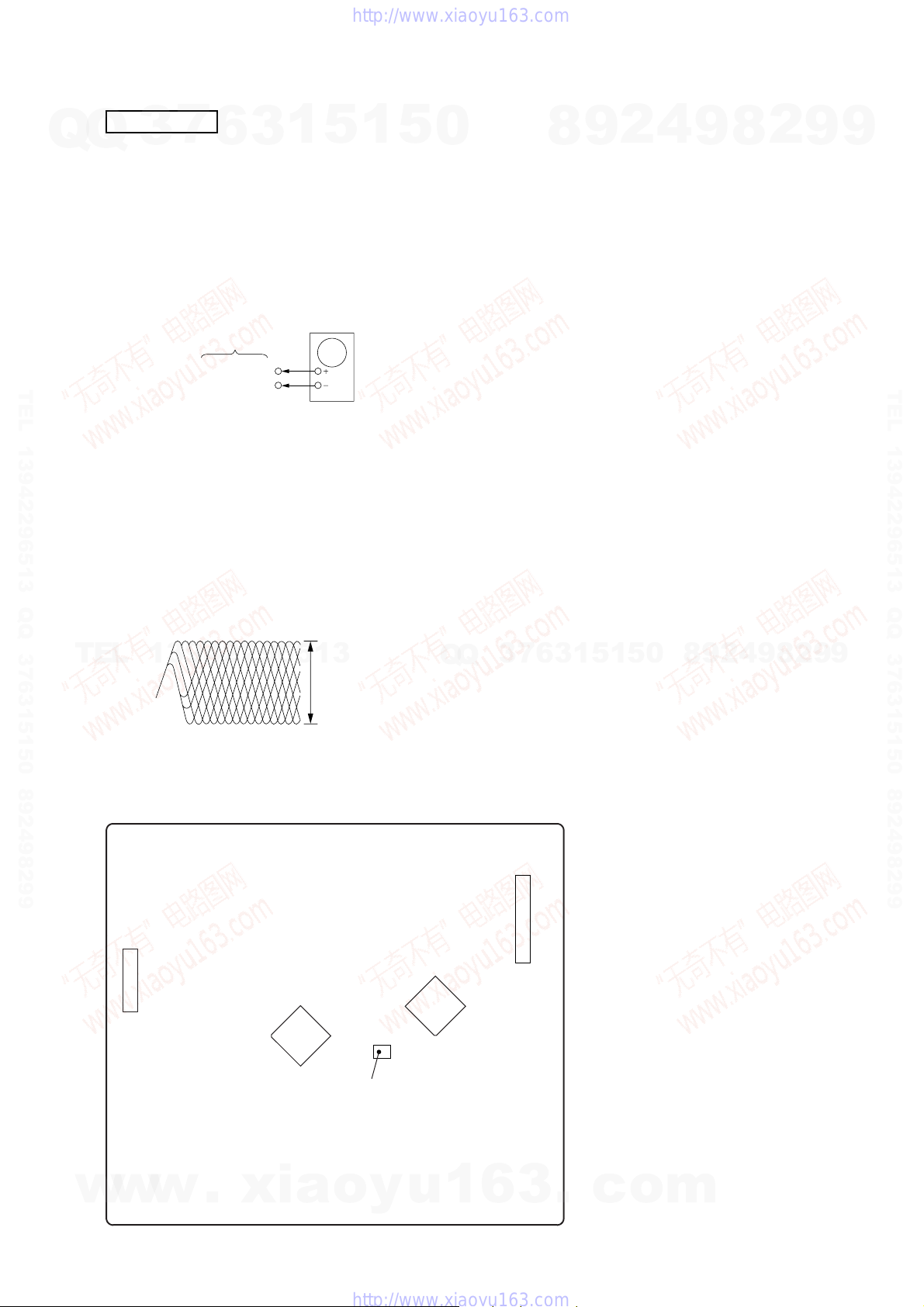
Procedure :
1. Connect an oscilloscope to pin q; (IC751).
2. Turn the power on.
3. Load a disc (YEDS-18) and playback the number five track.
4. Confirm that oscilloscope waveform is clear and check RF signal
level is correct or not.
IC751 pin q;
GND
BD board
oscilloscope
Note : Clear RF signal wav eform means that the shape “ ◊ ” can be clearly
distinguished at the center of the waveform.
RF signal waveform
VOLT/DIV : 200mV
TIME/DIV : 500ns
level : 1.4 to 2.1 Vp-
p
Note :
1. CD Block is basically designed to operate without adjustment.
Therefore, check each item in order given.
2. Use YEDS-18 disc (3-702-101-01) unless otherwise indicated.
3. Use an oscilloscope with more than 10MΩ impedance.
4. Clean the object lens by an applicator with neutral detergent
when the signal level is low than specified value with the
following checks.
w
w
w
.
x
i
a
o
y
u
1
6
3
.
c
o
m
Q
Q
3
7
6
3
1
5
1
5
0
9
9
2
8
9
4
2
9
8
T
E
L
1
3
9
4
2
2
9
6
5
1
3
9
9
2
8
9
4
2
9
8
0
5
1
5
1
3
6
7
3
Q
Q
TEL 13942296513 QQ 376315150 892498299
TEL 13942296513 QQ 376315150 892498299
http://www.xiaoyu163.com
http://www.xiaoyu163.com

18
HCD-RG66
SECTION 5
DIAGRAMS
Note on Schematic Diagram:
• All capacitors are in µF unless otherwise noted. pF: µµF
50 WV or less are not indicated except for electrolytics
and tantalums.
• All resistors are in Ω and
1
/
4
W or less unless otherwise
specified.
•
f
: internal component.
• C : panel designation.
Note on Printed Wiring Boards:
• X : parts extracted from the component side.
• b : Pattern from the side which enables seeing.
• Indication of transistor.
• A : B+ Line.
• B : B– Line.
• H : adjustment for repair.
•Voltages and waveforms are dc with respect to ground
under no-signal (detuned) conditions.
•Voltages are taken with a VOM (Input impedance 10 MΩ).
Voltage variations may be noted due to normal produc-
tion tolerances.
no mark : FM
< >: CD
[]: TAPE
•Waveforms are taken with a oscilloscope.
Voltage variations may be noted due to normal produc-
tion tolerances.
• Circled numbers refer to waveforms.
• Signal path.
F : FM
E : PB (DECK A)
d : PB (DECK B)
G : REC (DECK B)
J : CD
c : DIGITAL OUT
•Abbreviation
AUS: Australian model.
SP : Singapore model.
THIS NOTE IS COMMON FOR PRINTED WIRING BOARDS AND SCHEMATIC DIAGRAMS.
(In addition to this, the necessary note is printed in each bloc k.)
C
B
These are omitted.
E
Q
B
These are omitted.
CE
Q
Note: The components identified by mark 0 or dotted line
with mark 0 are critical for safety.
Replace only with part number specified.
w
w
w
.
x
i
a
o
y
u
1
6
3
.
c
o
m
Q
Q
3
7
6
3
1
5
1
5
0
9
9
2
8
9
4
2
9
8
T
E
L
1
3
9
4
2
2
9
6
5
1
3
9
9
2
8
9
4
2
9
8
0
5
1
5
1
3
6
7
3
Q
Q
TEL 13942296513 QQ 376315150 892498299
TEL 13942296513 QQ 376315150 892498299
http://www.xiaoyu163.com
http://www.xiaoyu163.com
 Loading...