


HCD-GX45
Table of contents
 Loading...
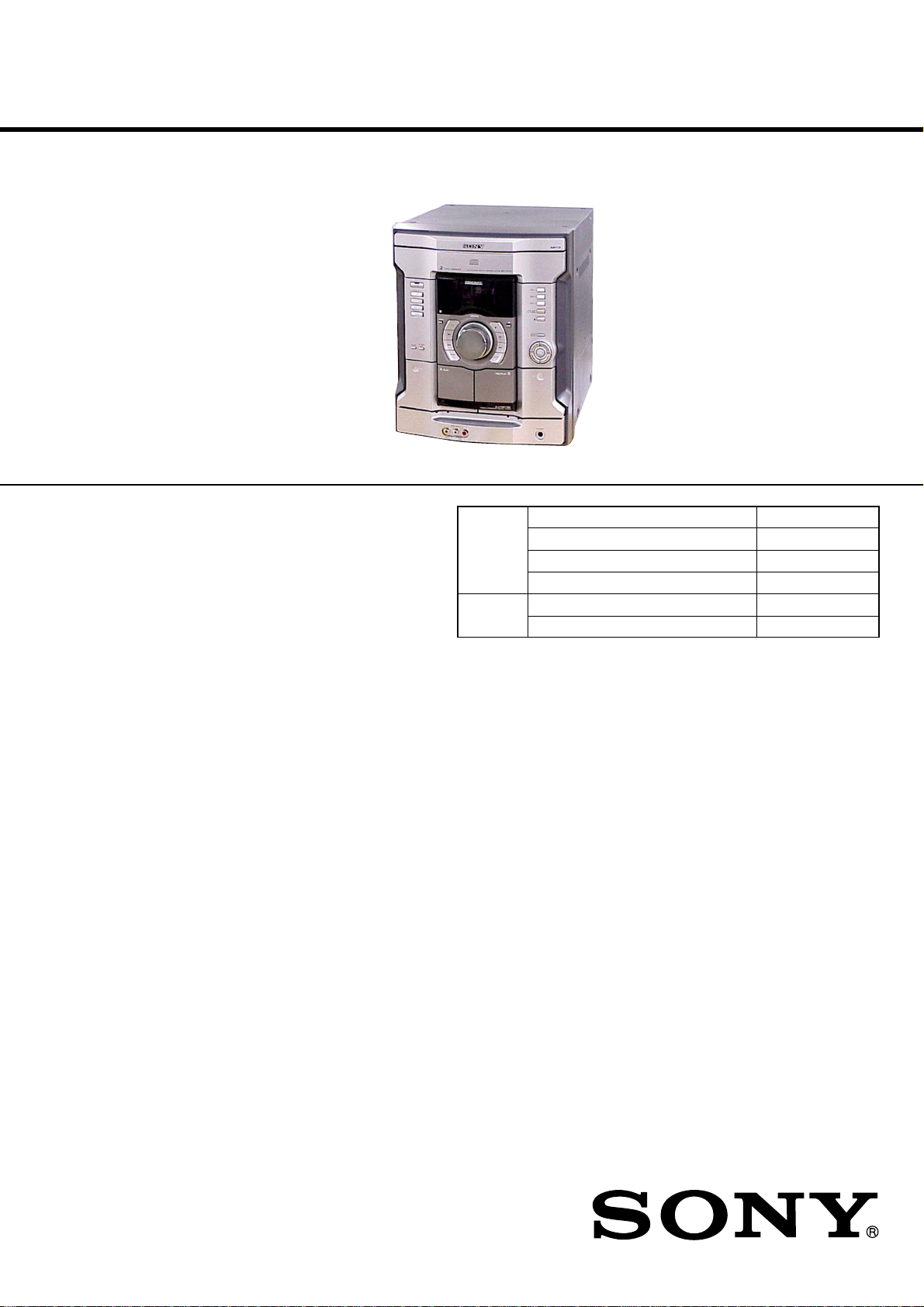
HCD-GX45/RG440
SERVICE MANUAL
Ver 1.0 2003. 07
• HCD-GX45/RG440 is the
tuner, deck, CD and amplifier
section in MHC-GX45/RG440S.
(Photo: HCD-GX45)
CD CD Mechanism Type CDM74F-K6BD71A
Section Base Unit Name BU-K6BD71A
Tape Deck Model Name Using Similar Machanism CX-JT8
Section Tape Transport Mechanism Type CWM43FF-13
US Model
Canadian Model
HCD-GX45
AEP Model
UK Model
Australian Model
HCD-RG440
Model Name Using Similar Mechanism NEW
Optical Pick-up Name KSS-213DCP
AUDIO POWER SPECIFICATIONS
(HCD-GX45 USA model only)
POWER OUTPUT AND TOTAL HARMONIC
DISTORTION:
With 6 ohm loads, both channels driven, from
120 – 10,000 Hz; rated 120 watts per channel
minimum RMS power, with no more than 10 %
total harmonic distortion from 250 milliwatts to
rated output.
Amplifier section
North American models:
HCD-GX45:
Front speaker
Continuous RMS power output (reference):
120 + 120 watts (6 ohms at
1 kHz, 10% THD)
Total harmonic distortion less than 0.07% (6 ohms at
1 kHz, 60 W)
Sub woofer
Continuous RMS power output (reference):
120 watts (6 ohms at
60 Hz, 10% THD)
Total harmonic distortion less than 0.07% (6 ohms at
60 Hz, 60 W)
European and Russian models:
HCD-RG440:
Front speaker
DIN power output (rated): 80 + 80 watts
(6 ohms at 1 kHz, DIN)
Continuous RMS power output (reference):
100 + 100 watts (6 ohms at
1 kHz, 10% THD)
Music power output (reference):
200 + 200 watts (6 ohms at
1 kHz, 10% THD)
SPECIFICATIONS
Sub woofer
DIN power output (rated): 80 watts (6 ohms at
60 Hz, DIN)
Continuous RMS power output (reference):
100 watts (6 ohms at
60 Hz, 10% THD)
Music power output (reference):
200 watts (6 ohms at
60 Hz, 10% THD)
Other models:
HCD-RG440:
The following measured at AC 120, 220, 240 V,
50/60 Hz
DIN power output (rated): 80 + 80 watts
(6 ohms at 1 kHz, DIN)
Continuous RMS power output (reference):
100 + 100 watts (6 ohms at
1 kHz, 10% THD)
Inputs
GAME INPUT AUDIO L/R (phono jacks):
voltage 250 mV,
impedance 47 kilohms
GAME INPUT VIDEO (phono jack):
1 Vp-p, 75 ohms
Outputs
PHONES (stereo mini jack):
accepts headphones of
8 ohms or more
– Continued on next page –
COMPACT DISC DECK RECEIVER
9-961-068-01
2003G04-1
© 2003. 07
Sony Corporation
Home Audio Company
Published by Sony Engineering Corporation
1

HCD-GX45/RG440
VIDEO OUT (phono jack):max. output level
1 Vp-p, unbalanced, Sync
negative, load impedance
75 ohms
SPEAKER: accepts impedance of 6 to
16 ohms
SUB WOOFER OUT: accepts impedance of 6 to
16 ohms
CD player section
System Compact disc and digital
audio system
Laser Semiconductor laser
(λ=780 nm)
Emission duration:
continuous
Frequency response 2 Hz – 20 kHz (±0.5 dB)
Wavelength 780 – 790 nm
Signal-to-noise ratio More than 90 dB
Dynamic range More than 90 dB
Tape deck section
Recording system 4-track 2-channel, stereo
Frequency response 50 – 13,000 Hz (±3 dB),
using Sony TYPE I
cassettes
Tuner section
FM stereo, FM/AM superheterodyne tuner
FM tuner section
Tuning range
Russian models 65.0 – 74.0 MHz
(There is no stereo effect)
87.5 – 108.0 MHz
Other models 87.5 – 108.0 MHz
Antenna FM lead antenna
Antenna terminals 75 ohms unbalanced
Intermediate frequency 10.7 MHz
AM tuner section
Tuning range
Pan-American models: 530 – 1,710 kHz (with the tuning
interval set at 10 kHz)
531 – 1,710 kHz (with the tuning
interval set at 9 kHz)
European, Russian, Middle Eastern and Philippine models:
531 – 1,602 kHz (with the tuning
interval set at 9 kHz)
Other models: 530 – 1,710 kHz (with the tuning
interval set at 10 kHz)
531 – 1,602 kHz (with the tuning
interval set at 9 kHz)
Antenna AM loop antenna
Antenna terminals External antenna terminal
Intermediate frequency 450 kHz
Speaker
North American models:
Front speaker SS-RG440 for HCD-GX45:
Speaker system 3-way, 3-unit, bass-reflex
type
Speaker units
Sub Woofer: 13 cm, cone type
Woofer: 13 cm, cone type
Tweeter: 5 cm, cone type
Nominal impedance 6 ohms
Dimensions (w/h/d) Approx. 240 × 325 × 243 mm
Mass Approx. 4.3 kg net per
speaker
Sub woofer speaker SS-WG990 for HCD-GX45:
Speaker system Bass-reflex type
Speaker units
Woofer: 20 cm, cone type
Nominal impedance 6 ohms
Dimensions (w/h/d) Approx. 265 × 325 × 350 mm
Mass Approx. 6.4 kg
European and Russian models:
Front speaker SS-RG440 for HCD-RG440:
Speaker system 3-way, 3-unit, bass-reflex
type
Speaker units
Woofer: 13 cm, cone type
Sub Woofer: 13 cm, cone type
Tweeter: 5 cm, cone type
Nominal impedance 6 ohms
Dimensions (w/h/d) Approx. 240 × 325 × 243 mm
Mass Approx. 4.3 kg net per
speaker
Sub woofer speaker SS-WG990 for HCD-RG440:
Speaker system Bass-reflex type
Speaker units
Woofer: 20 cm, cone type
Nominal impedance 6 ohms
Dimensions (w/h/d) Approx. 265 × 325 × 350 mm
Mass Approx. 6.4 kg
General
Power requirements
North American models: 120 V AC, 60 Hz
European and Russian models:
230 V AC, 50/60 Hz
Australian model: 230 – 240 V AC, 50/60 Hz
Argentine model: 220 V AC, 50/60 Hz
Mexican model: 127 V AC, 60 Hz
Saudi Arabian model: 120 – 127 V/220 V or
230 – 240 V AC,
50/60 Hz
Adjustable with voltage
selector
Korean model: 220 V AC, 60 Hz
Other models: 120 V, 220 V or 230 –
240 V AC, 50/60 Hz
Adjustable with voltage
selector
Power consumption
USA model:
HCD-GX45: 180 watts
European and Russian models:
HCD-RG440: 150 watts
0.35 watts (at the Power
Saving Mode)
Other models:
HCD-RG440: 150 watts
Dimensions (w/h/d) Approx. 280 × 325 × 407 mm
Mass
North American models:
HCD-GX45: Approx. 9.0 kg
European and Russian models:
HCD-RG440: Approx. 9.0 kg
Supplied accessories: AM loop antenna (1)
Remote Commander (1)
Batteries (2)
FM lead antenna (1)
Speaker pads (12)
Design and specifications are subject to change without
notice.
SAFETY-RELATED COMPONENT WARNING!!
COMPONENTS IDENTIFIED BY MARK 0 OR DOTTED LINE
WITH MARK 0 ON THE SCHEMATIC DIAGRAMS AND IN
THE PARTS LIST ARE CRITICAL TO SAFE OPERATION.
REPLACE THESE COMPONENTS WITH SONY P ARTS WHOSE
PART NUMBERS APPEAR AS SHOWN IN THIS MANUAL OR
IN SUPPLEMENTS PUBLISHED BY SONY.
2
ATTENTION AU COMPOSANT AYANT RAPPORT
À LA SÉCURITÉ!!
LES COMPOSANTS IDENTIFIÉS P AR UNE MARQUE 0 SUR LES
DIAGRAMMES SCHÉMATIQUES ET LA LISTE DES PIÈCES
SONT CRITIQUES POUR LA SÉCURITÉ DE FONCTIONNEMENT.
NE REMPLACER CES COMPOSANTS QUE PAR DES PIÈCES
SONY DONT LES NUMÉROS SONT DONNÉS DANS CE MANUEL
OU DANS LES SUPPLÉMENTS PUBLIÉS PAR SONY.
HCD-GX45/RG440
CAUTION
Use of controls or adjustments or performance of procedures
other than those specified herein may result in hazardous
radiation exposure.
Notes on Chip Component Replacement
• Never reuse a disconnected chip component.
• Notice that the minus side of a tantalum capacitor may be
damaged by heat.
Flexible Circuit Board Repairing
• Keep the temperature of soldering iron around 270°C during
repairing.
• Do not touch the soldering iron on the same conductor of the
circuit board (within 3 times).
• Be careful not to apply force on the conductor when soldering
or unsoldering.
NOTES ON HANDLING THE OPTICAL PICK-UP BLOCK
OR BASE UNIT
The laser diode in the optical pick-up block may suffer electrostatic
breakdown because of the potential difference generated by the
charged electrostatic load, etc. on clothing and the human body.
During repair, pay attention to electrostatic break-down and also
use the procedure in the printed matter which is included in the
repair parts.
The flexible board is easily damaged and should be handled with
care.
NOTES ON LASER DIODE EMISSION CHECK
The laser beam on this model is concentrated so as to be focused on
the disc reflective surface by the objective lens in the optical pickup block. Therefore, when checking the laser diode emission,
observe from more than 30 cm away from the objective lens.
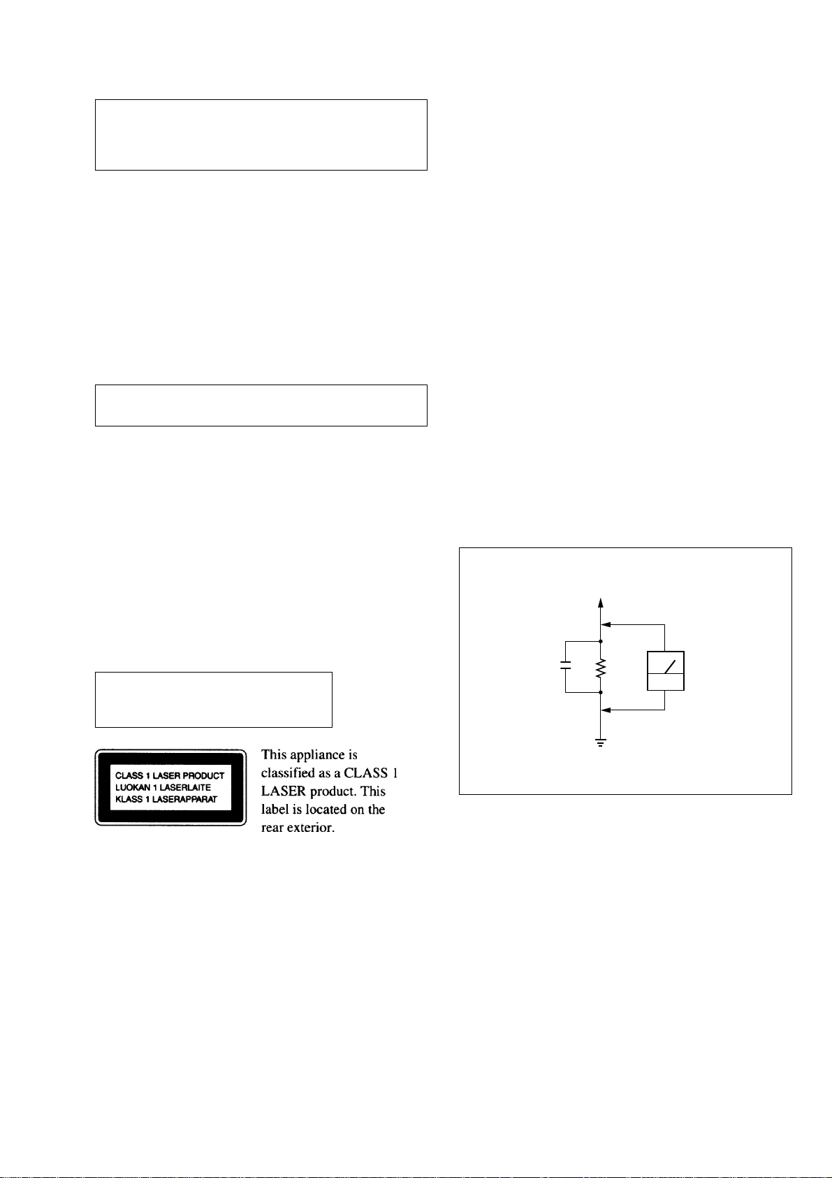
Laser component in this product is capable
of emitting radiation exceeding the limit for
Class 1.
SAFETY CHECK-OUT
After correcting the original service problem, perform the following
safety check before releasing the set to the customer:
Check the antenna terminals, metal trim, “metallized” knobs, screws,
and all other exposed metal parts for A C leakage. Check leakage as
described below.
LEAKAGE TEST
The AC leakage from any exposed metal part to earth ground and
from all exposed metal parts to any exposed metal part having a
return to chassis, must not exceed 0.5 mA (500 microamperes).
Leakage current can be measured by any one of three methods.
1. A commercial leakage tester, such as the Simpson 229 or RCA
WT-540A. Follow the manufacturers’ instructions to use these
instruments.
2. A battery-operated AC milliammeter. The Data Precision 245
digital multimeter is suitable for this job.
3. Measuring the voltage drop across a resistor by means of a V OM
or battery-operated A C v oltmeter. The “limit” indication is 0.75
V, so analog meters must have an accurate low-voltage scale. The
Simpson 250 and Sanwa SH-63Trd are examples of a passive
VOM that is suitable. Nearly all battery operated digital
multimeters that have a 2V AC range are suitable. (See Fig. A)
To Exposed Metal
Parts on Set
0.15µF
1.5k
Ω
AC
voltmeter
(0.75V)
SETTING AND RELEASING THE CD DISC TRAY LOCK
FUNCTION
This set has a disc tray lock function to prevent discs for
demonstration at shops from theft. While this lock function is set,
the tray will not be delivered out even when the OPEN/CLOSE
button is pressed.
Setting method:
Press the OPEN/CLOSE button while pressing the STOP button.
After a few seconds, the message “LOCKED” will appear on the
fluorescent indicator tube with the tray locked.
Releasing method:
Just as the lock is set, press the OPEN/CLOSE button while
pressing the STOP button.
After a few seconds, the message “UNLOCKED” will appear with
the lock released.
Earth Ground
Fig. A. Using an AC voltmeter to check AC leakage.
LASER DIODE AND FOCUS SEARCH OPERATION
CHECK
Carry out the “S curve check” in “CD section adjustment” and check
that the S curve waveforms is output three times.
3
HCD-GX45/RG440
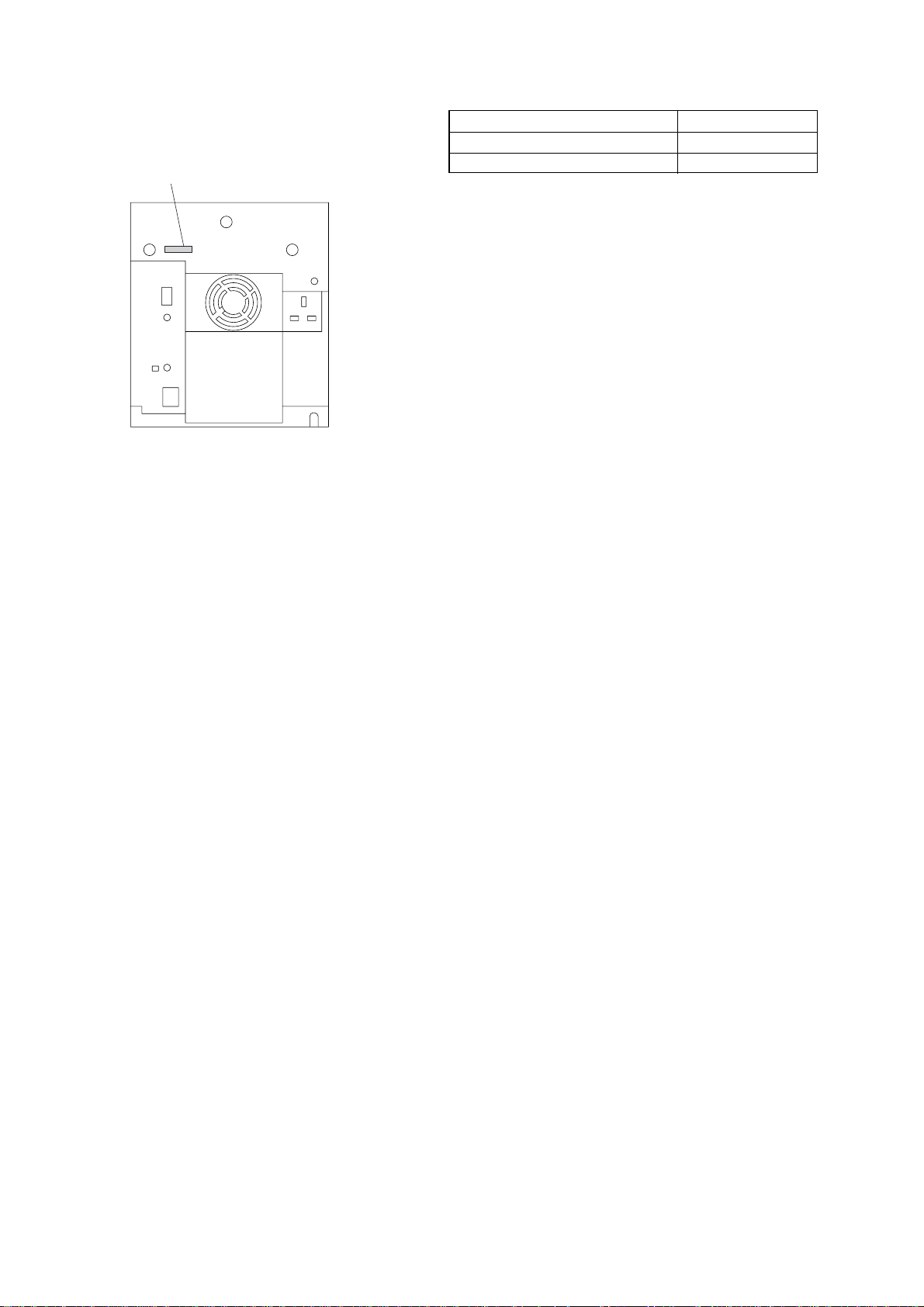
MODEL IDENTIFICATION
– BACK PANEL –
PARTS No.
TABLE OF CONTENTS
1. GENERAL
Main Unit ................................................................................ 5
Remote Control ....................................................................... 5
2. DISASSEMBLY
2-1. Case (Top) ........................................................................... 7
2-2. CD Door .............................................................................. 7
2-3. CD Mechanism Block ......................................................... 8
2-4. Front Panel Section ............................................................. 9
2-5. Tape Mechanism Deck ...................................................... 10
2-6. Panel Board, 6 Stream Led Board, Remote Board............ 10
2-7. Game Jack Board, H/P Jack Board ................................... 11
2-8. Back Panel Section............................................................ 11
2-9. Main Board ....................................................................... 12
2-10. Power Amp Board, Subwoofer Board............................... 12
2-11. SW Board, Driver Board................................................... 13
2-12. CD Block Assy.................................................................. 13
2-13. Sensor Board ..................................................................... 14
2-14. Motor (TB) Board ............................................................. 14
2-15. Motor (LD) Board ............................................................. 15
2-16. BD Board .......................................................................... 15
2-17. Optical Pick-up ................................................................. 16
3. TEST MODE ..................................................................... 17
4. ELECTRICAL ADJUSTMENTS................................. 20
5. DIAGRAMS
5-1. IC Pin Descriptions ........................................................... 21
5-2. Block Diagram –CD Section–........................................... 25
5-3. Block Diagram –Tuner/Tape/Panel Section– ....................26
5-4. Block Diagram –Amp/Power Supply Section–................. 27
5-5. Block Diagram –Sub Woofer Section– ............................. 28
5-6. Note for Printed Wiring Boards
and Schematic Diagrams .................................................. 29
5-7. Waveforms......................................................................... 29
MODEL PARTS No.
GX45: US, CND 4-244-697-31
RG440: AEP , UK, AUS 4-244-697-41
• Abbreviation
CND : Canadian model
AUS : Australian model
5-8. Circuit Boards Location .................................................... 29
5-9. Printed Wiring Board –CD Mechanism Section (1/2)– .... 30
5-10. Schematic Diagram –CD Mechanism Section (1/2)– ....... 31
5-11. Printed Wiring Boards –CD Mechanism Section (2/2)– ...32
5-12. Schematic Diagram –CD Mechanism Section (2/2)– ....... 33
5-13. Schematic Diagram –Main Section (1/4)– ........................34
5-14. Schematic Diagram –Main Section (2/4)– ........................35
5-15. Schematic Diagram –Main Section (3/4)– ........................36
5-16. Schematic Diagram –Main Section (4/4)– ........................37
5-17. Printed Wiring Board –Main Section– .............................. 38
5-18. Printed Wiring Boards and Schematic Diagram
–Jack Section– ................................................................... 39
5-19. Printed Wiring Boards –Panel Section– ............................ 40
5-20. Schematic Diagram –Panel Section– ................................ 41
5-21. Printed Wiring Board –Sub Woofer Section– ................... 42
5-22. Schematic Diagram –Sub Woofer Section– ...................... 43
5-23. Schematic Diagram –Power Amp Section (1/2)– ............. 44
5-24. Schematic Diagram –Power Amp Section (2/2)– ............. 45
5-25. Printed Wiring Board –Power Amp Section– ................... 46
5-26. Printed Wiring Board
–Transformer Section– ...................................................... 47
5-27. Schematic Diagram –Transformer Section– ..................... 48
5-28. IC Block Diagrams............................................................ 49
6. EXPLODED VIEWS
6-1. Main Section ..................................................................... 52
6-2. Front Panel Section (1)...................................................... 53
6-3. Front Panel Section (2)...................................................... 54
6-4. Front Panel Section (3)...................................................... 55
6-5. Main Board Section .......................................................... 56
6-6. CD Mechanism Deck Section (1) ..................................... 57
6-7. CD Mechanism Deck Section (2) ..................................... 58
6-8. Base Unit Section ..............................................................59
7. ELECTRICAL PARTS LIST ........................................ 60
4
SECTION 1
GENERAL
HCD-GX45/RG440
This section is extracted
from instruction manual.
5
HCD-GX45/RG440
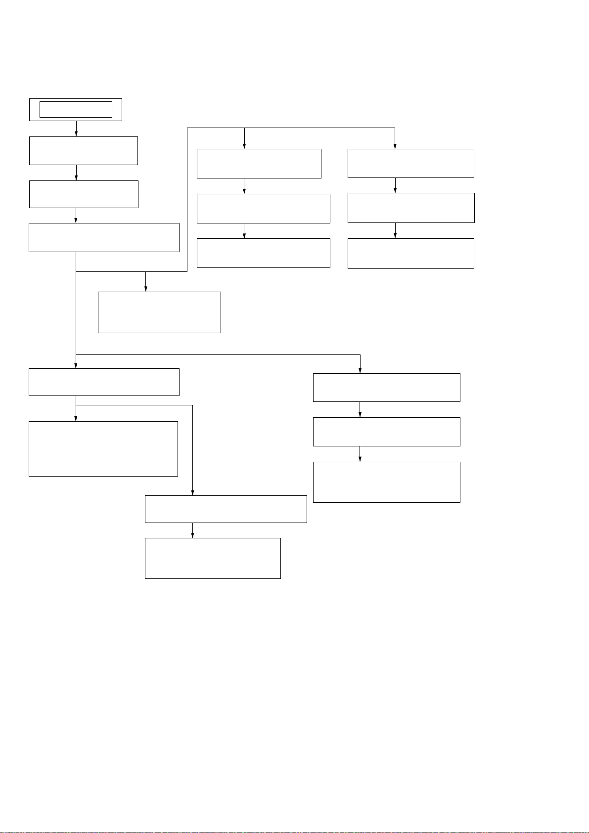
Note : Disassemble the unit in the order as shown below.
SET
2-1. CASE (TOP)
(Page 7)
2-2. CD DOOR
(Page 7)
2-3. CD MECHANISM BLOCK
(Page 8)
2-11. SW BOARD,
DRIVER BOARD
(Page 13)
2-13. SENSOR BOARD
2-14. MOTOR (TB) BOARD
2-15. MOTOR (LD) BOARD
SECTION 2
DISASSEMBLY
(Page 14)
(Page 14)
(Page 15)
2-12. CD BLOCK ASSY
(Page 13)
2-16. BD BOARD
(Page 15)
2-17. OPTICAL PICK-UP
(Page 16)
2-4. FRONT PANEL SECTION
(Page 9)
2-6. PANEL BOARD,
6 STREAM LED BOARD,
REMOTE BOARD
(Page 10)
2-5. TAPE MECHANISM DECK
2-7. GAME JACK BOARD,
2-8. BACK PANEL SECTION
(Page 11)
2-9. MAIN BOARD
(Page 12)
2-10. POWER AMP BOARD,
SUBWOOFER BOARD
(Page 12)
(Page 10)
H/P JACK BOARD
(Page 11)
6
Note : Follow the disassembly procedure in the numerical order given.
)
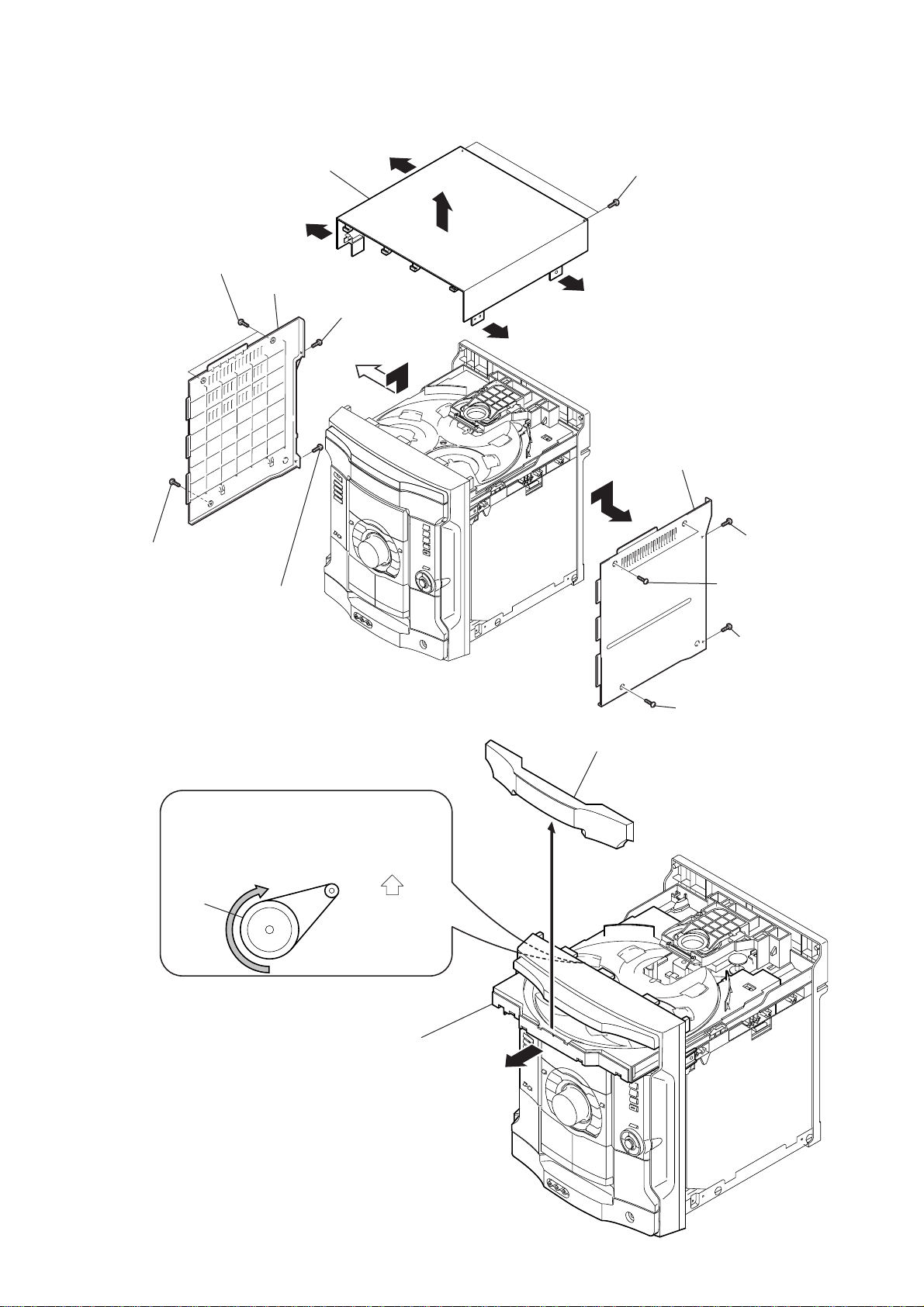
2-1. CASE (TOP)
HCD-GX45/RG440
6
two screws (case 3 TP2)
7
screw (case 3 TP2)
9
(+BVTP 3
qf
case (side-L)
screw
case (top)
qs
×
10)
qs
8
screw
(+BVTP 3
×
q;
10)
qd
qs
qs
qa
two screws (+BVTP 3
case (side-R)
5
×
10)
3
screw
(+BVTP 3
1
two screws
(case 3 TP2)
×
10
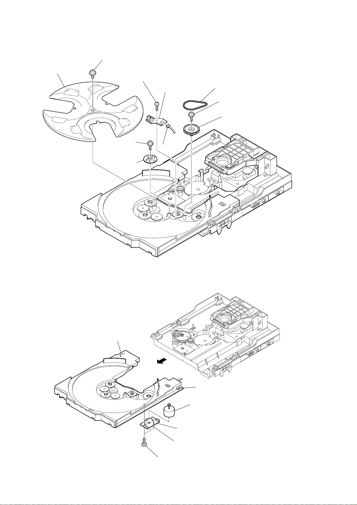
2-2. CD DOOR
CD mechanism deck (CDM74F-K6BD71B)
1
Turn the pulley to the direction of the arrow.
pulley
Front panel side
2
Pull-out the disc tray.
3
4
CD door
4
(+BVTP 3
2
screw (case 3 TP2)
screw
×
10)
7
HCD-GX45/RG440
)
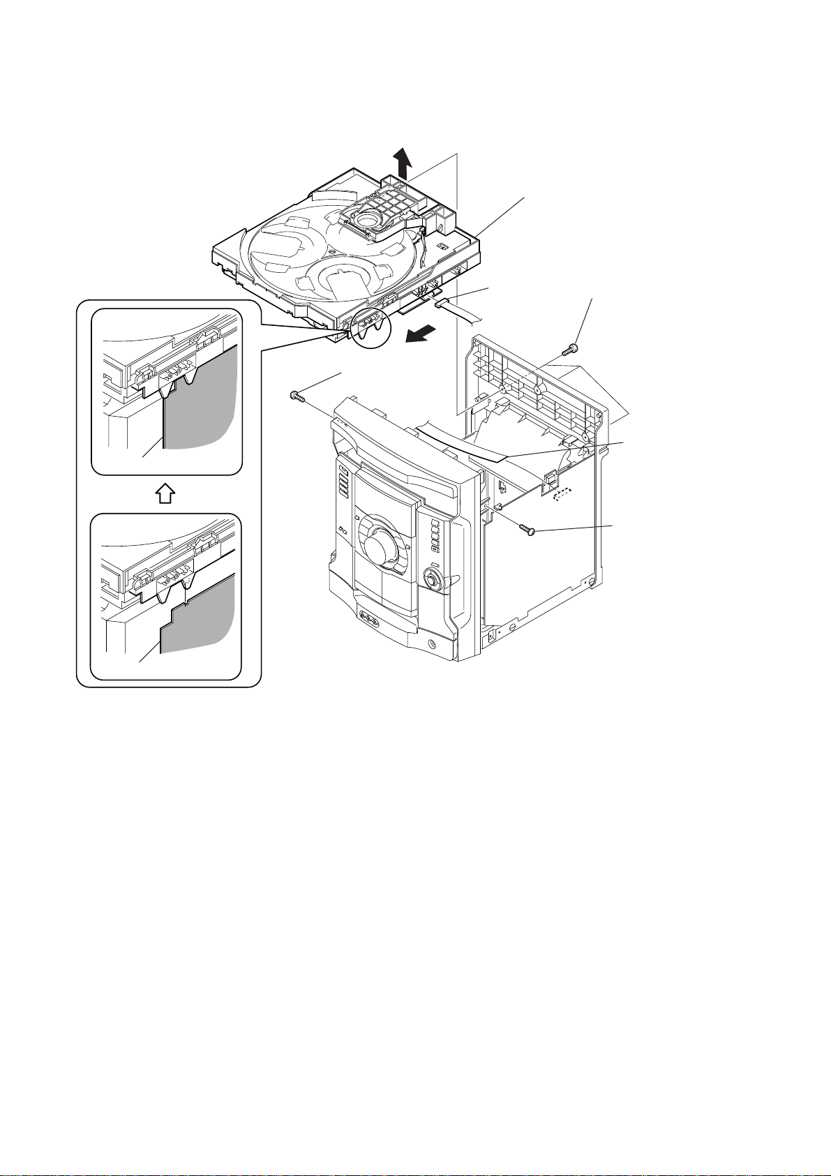
2-3. CD MECHANISM BLOCK
5
3
screw
(+BVTP 3
6
8
CD mechanism block
1
CN701
×
10)
2
three
(+BVTP 3
screws
×
10)
MAIN board
MAIN board
7
CN312
(flat type)
4
screw
(+BVTP 3
×
10
8
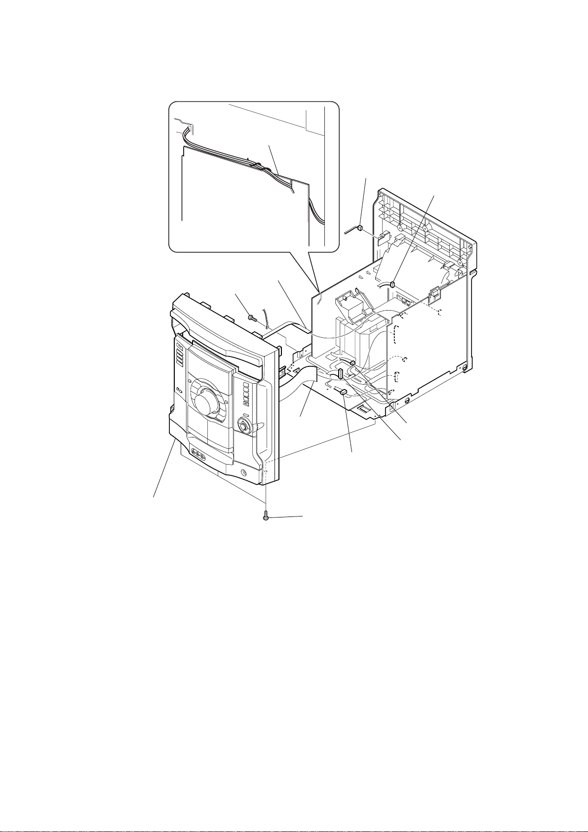
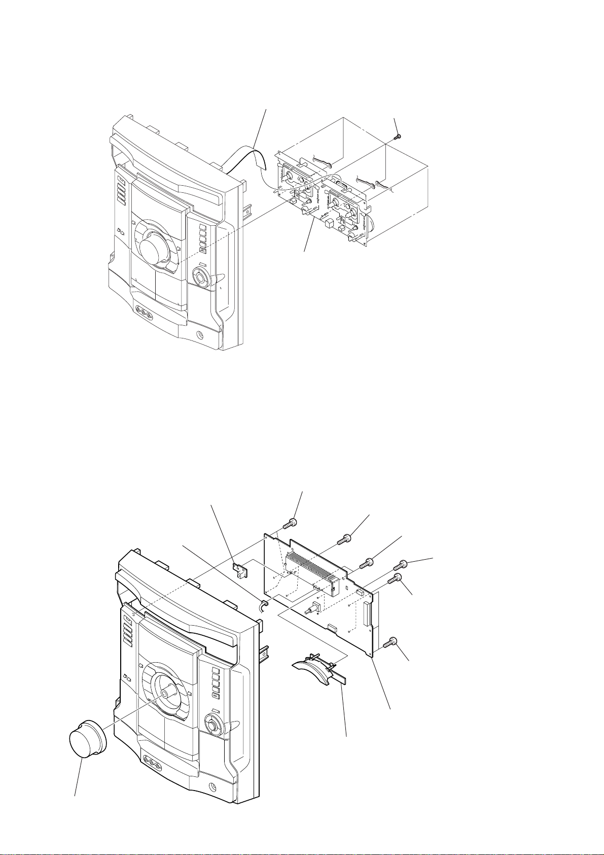
2-4. FRONT PANEL SECTION
8
(+BVTP 3
screw
3
×
8)
TRANS board
CN311
(flat type)
1
CN003
HCD-GX45/RG440
4
CN305
0
front panel section
2
CN304
(flat type)
7
9
three screws (+BVTP 3
CN310
× 8
6
5
CN202
)
CN203
9
HCD-GX45/RG440
)
)
2-5. TAPE MECHANISM DECK
1
connector
3
tape mechanism deck
2
six
screws
(+BVTP 2.6
×
8
2-6. PANEL BOARD, 6 STREAM LED BOARD, REMOTE BOARD
5
three
(+BVTP 2.6
0
CN607
qa
REMOTE board
screws
×
8)
6
two
(+BVTP 2.6
9
6 STREAM LED board
screws
×
8
two
(+BVTP 2.6
3
(+BVTP 2.6
2
three
(+BVTP 2.6
7
PANEL board
8)
screws
×
4
two
(+BVTP 2.6
two
screws
screws
8)
screws
×
8)
×
8)
×
8
10
1
volume knob
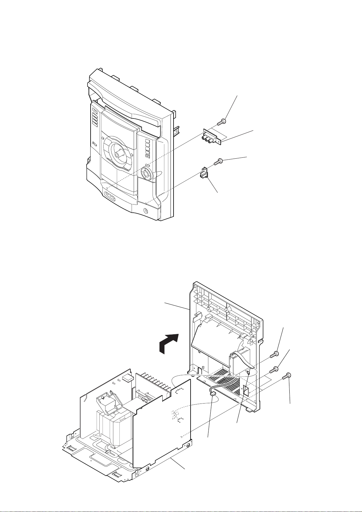
2-7. GAME JACK BOARD, H/P JACK BOARD
d
1
two
screws
(+BVTP 2.6
2
GAME JACK boar
3
screw
(+BVTP 2.6
HCD-GX45/RG440
×
8)
×
8)
2-8. BACK PANEL SECTION
7
back panel section
5
4
H/P JACK board
4
screw
(+BVTP 3
3
two
screws
(+BVTP 3
×
10)
×
10)
6
CN303
chassis section
1
CN101
(flat type)
2
two
screws
(+BVTT 3
×
8)
11
HCD-GX45/RG440
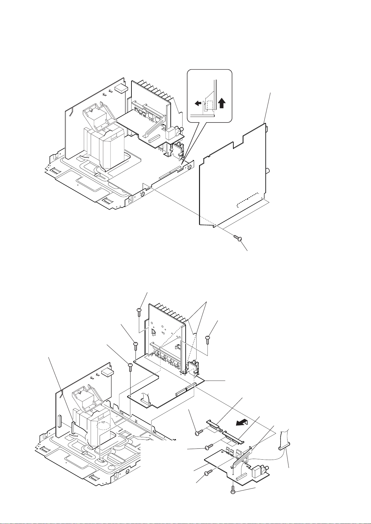
d
2-9. MAIN BOARD
MAIN board
2
MAIN boar
2-10. POWER AMP BOARD, SUBWOOFER BOARD
3
screw
(+BVTP 3
5
screw
1
CN902
(+BVTP 3
6
screw
(+BVTP 3
×
10)
×
10)
×
8)
9
(transistor)
two
two claws
screws
4
screw
(+BVTP 3
7
POWER AMP board
qd
1
two
(+BVTP 3
×
8)
0
bracket (A)
qs
screws
×
bracket (B)
qg
10)
bracket (PWB)
12
qa
three
(transistor)
qh
SUBWOOFER board
screws
8
screw
(+BVTT 3
×
10)
qf
screw
(+BVTT 3
×
2
10)
CN401
2-11. SW BOARD, DRIVER BOARD
d
2
SW board
7
CN702 (flat type)
4
CN703
6
DRIVER boar
HCD-GX45/RG440
2-12. CD BLOCK ASSY
3
1
screw
(+BTTP (M2.6))
2
holder (213) assy
qa
CD block assy
9
two
insulators
CN704
5
two
screws
(+BTTP (M2.6))
0
1
floating
(+PTPWH M2.6)
5
two
insulators
two
coil springs
4
(insulator)
screw
8
two
coil springs
(insulator)
7
two stoppers (BU)
6
(BTTP M2.6)
two screws
3
two floating
(+PTPWH M2.6)
screws
13
HCD-GX45/RG440
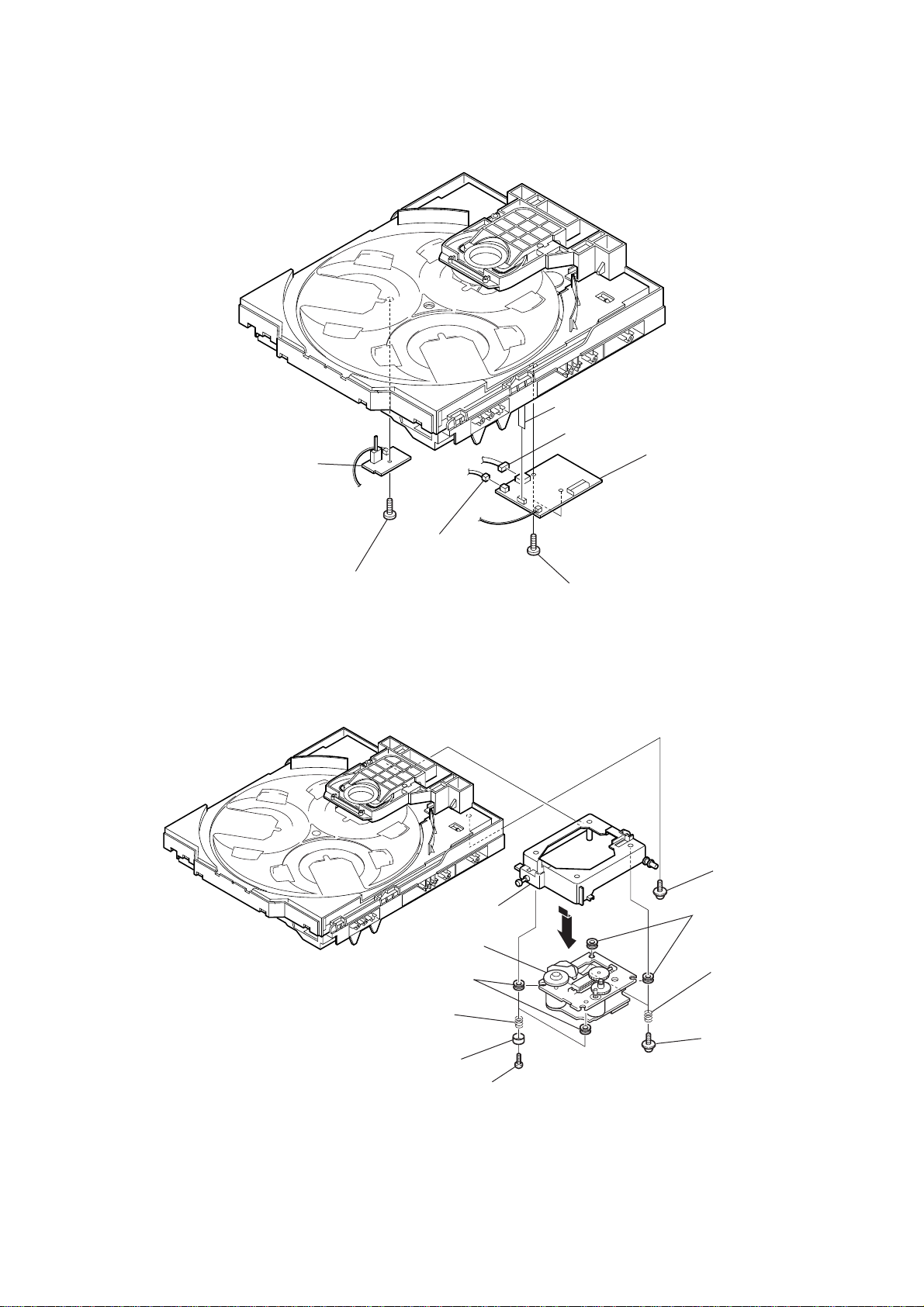
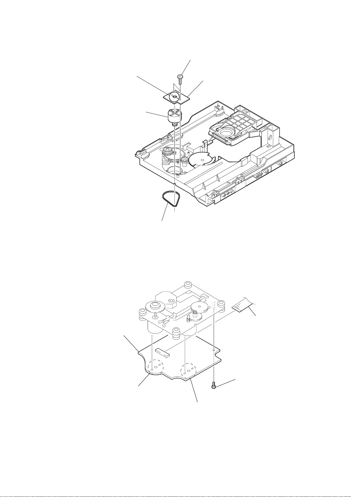
2-13. SENSOR BOARD
2
tray
1
floating
(+PTPWH M2.6)
6
floating
(+PTPWH M2.6)
7
gear (geneva)
screw
8
screw
(+BTTP (M2.6))
screw
9
SENSOR board
0
CN731
3
belt (table)
4
floating
(+PTPWH M2.6)
5
screw
pulley (table)
2-14. MOTOR (TB) BOARD
claw
1
claw
5
table motor assy (M741)
3
MOTOR (TB) board
4
Remove the two solderings of motor.
14
2
two
screws
(+BTTP (M2.6))
)
2-15. MOTOR (LD) BOARD
4
Remove the two solderings of motor.
5
loading motor assy (M751)
2
two
screws
(+BTTP (M2.6))
3
MOTOR (LD) board
HCD-GX45/RG440
2-16. BD BOARD
2
1
4
BD board
Remove the two solderings of motor.
belt (loading)
5
1
screw
(+BTP 2.6
CN708 (flat type
×
8)
3
Remove the two solderings of motor.
15

HCD-GX45/RG440
2-17. OPTICAL PICK-UP
3
Remove the optical pick-up
(KSS-213D) in the direction
of the arrow
B
B
.
1
gear (A)
2
sled shaft
A
1
Slide the lever
in the direction of arrow
A
.
16

SECTION 3
TEST MODE
HCD-GX45/RG440
[COLD RESET]
• The cold reset clears all data including preset data stored in the
RAM to initial conditions. Execute this mode when returning the
set to the customer.
Procedure:
1. Press the [POWER] key to turn the power ON.
2. Press three keys of x , [GROOVE] and [POWER] simultaneously.
3. The message “COLD RESET” is displayed on the fluorescent
indicator tube momentarily, then becomes standby states.
[TUNER STEP CHANGE-OVER]
(Except AEP and UK models)
•A step of AM channels can be changed over between 9 kHz and
10 kHz.
Procedure:
1. Press the [POWER] key to turn the power ON.
2. Press the [TUNER BAND] key to select “AM”.
3. Press the [POWER] key to turn the power OFF.
4. Press two keys of [TUNER/BAND] and [POWER] simultaneously.
5. The message “9K STEP” or “10K STEP” is displayed on the
fluorescent indicator tube, and thus the channel step is changed
over.
[CD SHIP MODE]
•This mode moves the optical pick-up to the position durable to
vibration. Use this mode when returning the set to the customer
after repair.
Procedure:
1. Press the [POWER] key to turn the power ON.
2. Press the [CD] key to select “CD”.
3. Press two keys of [CD] and [POWER] simultaneously.
4. The message “LOCK” is displayed on the fluorescent indicator
tube, and the CD ship mode is set.
[CD TRAY LOCK MODE]
•This mode is used to unable to take sample disc out of tray in the
shop.
Procedure:
1. Press the [POWER] key to turn the power ON.
2. Press the [CD] key to select “CD”.
3. Set disc on the tray.
4. While pressing the x key, press the Z key for 5 seconds.
5. The message “LOCKED” is displayed on the fluorescent
indicator tube and the tray is locked. (Even if pressing
the Z key, the message “LOCKED” is displayed on the
fluorescent indicator tube and the tray is locked)
6. To release from this mode, while pressing the x key, press
the Z key for 5 seconds.
7. The message “UNLOCKED” is displayed on the fluorescent
indicator tube and the tray is unlocked.
[AMP TEST MODE]
•This mode is used to set the parameter of AMP IC for adjustment
of tone quality and VACS level and display VACS status.
Procedure:
1. Press the [POWER] key to turn the power ON.
2. Press three keys of x , [GAME EQ] and [EFFECT ON/OFF]
simultaneously.
3. When the AMP test mode is activated, the message “AMP
TEST” is displayed on the fluorescent indicator tube
momentarily.
4. Press two keys of [GAME EQ] and [DISC 2] simultaneously, mode
is changed over to parameter setting of AMP IC and display of
VACS status.
5. When the VACS status, the message VACS level, VACS signal
level, and VACS signal hold le vel is displayed on the fluorescent
indicator tube.
6. Press the [GROOVE] key, DBFB ON/OFF is changed over.
7. Press the [GAME MIXING] key, surround ON/OFF is changed
over.
8. To release from this mode, press two keys of [GAME EQ] and
[MOVIE EQ] simultaneously.
17
HCD-GX45/RG440
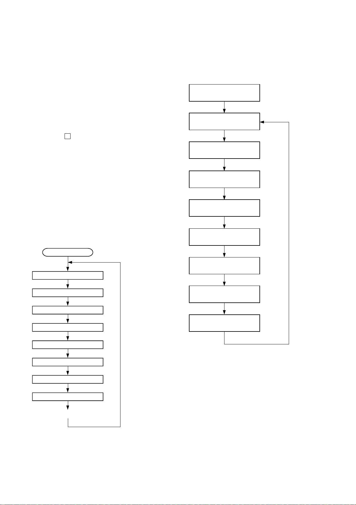
[AGING MODE]
• This mode can be used for operation check of CD section and
tape deck section.
CD section and tape deck section work in parallel.
If an error occurred:
The aging operation stops only an error occurred sections and
display then status.
If no error occurs:
The aging operation continues repeatedly.
Procedure:
1. Press the [POWER] key to turn the power ON.
2. Press the [CD] key to select “CD”.
3. Set disc on the tray and set tape into the deck.
4. Set the “ALL DISCS” mode and “REV OFF” mode.
5. Press three keys of x , [GAME EQ] and [DISC SKIP/EX-CHANGE]
simultaneously.
6. The message “AGING” is displayed on the fluorescent
indicator tube momentarily, then aging operations of CD and
tape are started at the same time.
7. To release from this mode, operate the “COLD RESET”.
1. Display at the Aging Mode
Display operating state of CD section and tape deck section
alternately.
If an error occurred, stop display which that section.
2. CD Section
The sequence during the aging mode is following as below.
Display at the aging mode is the same as the normal operation.
Aging mode sequence (CD section) :
3. Tape Deck Section
The sequence during the aging mode is following as below.
If an error occurred, stop display that step.
Aging mode sequence (tape deck section) :
Rewind the tape A and B
“AAG-1 or 2”
Shut off
FWD play the tape A
“AAG-3”
2 minutes
Fast forward the tape A
“AAG-4”
Shut off or 20 seconds
REV play the tape A
“AAG-5”
2 minutes
Rewind the tape A
“AAG-6”
Shut off
FWD play the tape B
“BAG-3”
Start (from disc 1)
Disc chucking
TOC read
Play first track for 2 seconds
Play last track for 2 seconds
EX-change open/close
Open the disc tray
Disc skip
Close the tray
Change the next disc.
2 minutes
Fast forward the tape B
“BAG-4”
Shut off or 20 seconds
REV play the tape B
“BAG-5”
2 minutes
Rewind the tape B
“BAG-6”
Shut off
Note: “*AG-*” is display of each step.
18

HCD-GX45/RG440
[GC TEST MODE]
• This mode is used to check the fluorescent indicator tube, LED
and key.
Procedure:
1. Press the [POWER] key to turn the power ON.
2. Press three keys of x , [GAME EQ] and [DISC 2] simultaneously.
3. Fluorescent indicator tube and LEDs are all turned ON.
4. Press two keys of [GAME EQ] and [DISC 2] simultaneously, mode
is changed over.
5. In the key check mode, press each key, the defined key number
of every each key list is displayed on the fluorescent indicator
tube.
6. In the key count check mode, “KEYCNT 0” is displayed on the
fluorescent indicator tube. Each time a key is pressed,
“KEYCNT” value increases. Howev er , once a key is pressed , it
is no longer taken into account.
7. In the headphone input check mode, connect the headphone,
the message “H_P ON” is displayed on the fluorescent
indicator tube, and disconnect the headphone, the message “H_P
OFF” is displayed on the fluorescent indicator tube.
8. In the volume check mode, turn the [VOLUME] knob, the
display on the fluorescent indicator tube is changed over to
“VOLUME UP”, “VOLUME FLAT” or “VOLUME DOWN”
[MC TEST MODE]
•This mode is used to check operations of Amplifier.
Procedure:
1. Press the [POWER] key to turn the power ON.
2. Press three keys of x , [GAME EQ] and [DISC 3] simultaneously.
3. When the MC test mode is activated, the message “TEST
MODE” is displayed on the fluorescent indicator tube
momentarily, then VACS level is displayed on the fluorescent
indicator tube.
4. Press the [MUSIC EQ] key, the display on the fluorescent
indicator tube is changed over to “GEQ MAX”, press the
[EFFECT ON/OFF] key, the display on the fluorescent indicator
tube is changed over to “GEQ FLAT”, press the [MOVIE EQ]
key, the display on the fluorescent indicator tube is changed
over to “GEQ MIN”,
5. Turn the [VOLUME] knob, the display on the fluorescent
indicator tube is changed over to “VOLUME MAX”, “V OLUME
16” or “VOLUME MIN”
6. Press the [GROOVE] key, VACS ON/OFF is changed over.
7. When the [REC PAUSE/START] ke y is pressed with a ta pe set in
the deck-B, the function is switched “MD” or “VIDEO” and
recording starts. When the m or M key is pressed during
recording, the tape is rewound back to the beginning of
recording, the function is switched to “T APE B”, then playback
starts.
8. When the [CD SYNC] key is pressed with the test tape (AMS-
100, AMS-110A) in the deck, number of space between tunes
is counted, then if AMS-110A is set, “OK” is displayed on the
fluorescent indicator tube and if AMS-100 is set, “NG” is
displayed on the fluorescent indicator tube.
9. To release from this mode, press the [POWER] key.
[MODEL, DESTINATION AND VERSION DISPLAY]
•This mode is used to check the model, destination and software
version.
Procedure:
1. Set to the standby state.
2. Press three keys of x , [GAME EQ] and [MOVIE EQ]
simultaneously.
3. When the model, destination and version display mode is
activated, the model an destination is displayed on the
fluorescent indicator tube.
4. Press two keys of [GAME EQ] and [DISC 2] simultaneously, mode
is changed over to model and destination display mode and
version display mode.
5. To release from this mode, press the two keys of [GAME EQ]
and [MOVIE EQ] simultaneously.
[CD ERROR CODE DISPLAY]
• This mode can be used for error display of CD section.
Procedure:
1. Press the [POWER] key to turn the power ON.
2. Press the [CD] key to select “CD”.
3. Press three keys of x , [GAME EQ] and [DISC 1] simultaneously .
Note: Error code is not displayed on the fluorescent indicator tube.
[CD SERVICE MODE]
•This mode can run the CD sled motor freely. Use this mode, for
instance, when cleaning the optical pick-up.
Procedure:
1. Press the [POWER] key to turn the power ON.
2. Press the [CD] key to select “CD”.
3. Press three keys of x , [GAME EQ] and Z simultaneously.
4. When the CD service mode is activated, the message
“TRA VERS ON” is displa yed on the fluorescent indicator tube.
5. Press the M key, optical pick-up move to outside track and
the message “SLED OUT” is displayed on the fluorescent
indicator tube.
6. Press the m key, optical pick-up move to inside track and
the message “SLED IN” is displayed on the fluorescent
indicator tube..
7. Press the [MOVIE EQ] key, traverse ON/OFF is changed over.
[5 REPEAT LIMIT CANCEL]
• Number of repeat for CD playback is 5 times when the repeat
mode is “REPEAT”. This mode is used to enables CD to repeat
playback for limitless times.
Procedure:
1. Press the [POWER] key to turn the power ON.
2. Press the [CD] key to select “CD”.
3. Press three keys of x , [GAME EQ] and G simultaneously.
19
HCD-GX45/RG440
p
p
SECTION 4
ELECTRICAL ADJUSTMENTS
CD SECTION
Note:
1. CD Block is basically designed to operate without adjustment.
Therefore, check each item in order given.
2. Use YEDS-18 (3-702-101-01) unless otherwise indicated.
3. Use an oscilloscope with more than 10MW impedance.
4. Clean the object lens by an applicator with neutral detergent
when the signal level is low than specified value with the
following checks.
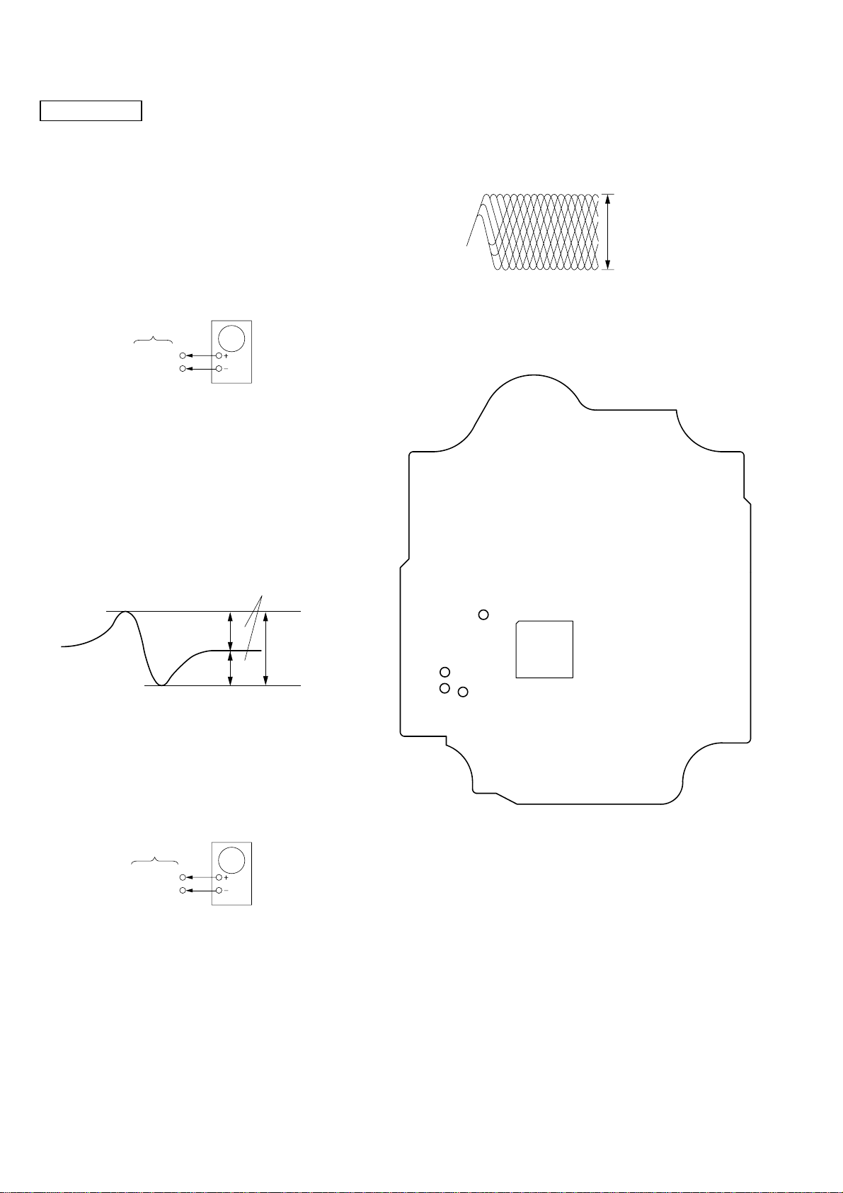
S-CURVE CHECK
Oscilloscope
BD board
TP(FE)
TP(VC)
Procedure :
1. Connect an oscilloscope to TP (FE) and TP (VC).
2. Turn the power on.
3. Load a disc (YEDS-18) and actuate the focus search. (In
consequence of open and close the disc tray, actuate the focus
search)
4. Confirm that the oscilloscope waveform (S-curve) is
symmetrical between A and B. And confirm peak to peak level
within 3 ± 0.5 Vp-p.
Note: Clear RF signal waveform means that the shape “ ◊ ” can be
clearly distinguished at the center of the waveform.
RF signal waveform
VOLT/DIV : 200mV
TIME/DIV : 500ns
level : 1.3
±
0.3Vp-
Connecting Location: BD board
– BD Board (Conductor side) –
S-curve waveform
symmetry
A
±
within 3
B
0.5Vp-
Note: •Try to measure several times to make sure than the ratio
of A : B or B : A is more than 10 : 7.
•Take sweep time as long as possible and light up the
brightness to obtain best waveform.
RF LEVEL CHECK
BD board
TP(RF)
TP(VC)
Procedure :
1. Connect an oscilloscope to TP (RF) and TP (VC).
2. Turn the power on.
3. Load a disc (YEDS-18) and playback.
4. Confirm that oscilloscope waveform is clear and check if RF
signal level is correct or not.
oscilloscope
TP (RF)
TP (VC)
TP (FE)
IC721
TP (TE)
20
HCD-GX45/RG440
SECTION 5
DIAGRAMS
5-1. IC PIN DESCRIPTIONS
• IC309 BU2099FV (MULTI CONTROLLER) (MAIN BOARD)
Pin No. Pin Name I/O Pin Description
1 VSS — Ground pin
2NC—Not used. (Open)
3DATAISerial data input from the tape mechanism controller
4 CLOCK I Serial data transfer clock signal input from the system controller
5 LCK I Serial data latch pulse clock signal input from the system controller
6 REC O Recording on/off control signal output “L”: recording
7BIAS O Recording bias on/off control signal output “L”: bias on
8A/BO
9 PB MUTE O
10 REC MUTE O
11 TUNER MUTE O Tuner muting on/off control signal output to the tuner unit “H”: muting on
12 LM-R (CD) O Loading motor drive signal output
13 LM-L (CD) O Loading motor drive signal output
14 TM-R (CD) O Table motor drive signal output
15 TM-L (CD) O Table motor drive signal output
16 SP RERAY O Front speaker on/off relay drive control signal output “L”: front speaker on
17 LINK/MATRIX O Surround speaker on/off relay drive control signal output “H”: surround speaker on
18 SO O Serial data output to the bass boost controller
19 OE — Not used. (Connect to ground.)
20 VDD — Power supply pin (+3.3 V)
Deck-A/B selection signal output to the deck-A/B select switch
“L”: deck-B, “H”: deck-A
Playback muting on/off control signal output to the recording/playback equalizer
amplifier “H”: muting on
Recording muting on/off control signal output to the recording/playback equalizer
amplifier “L”: muting on
21
HCD-GX45/RG440
• IC310 BU2099FV (BASS BOOST CONTROLLER) (MAIN BOARD)
Pin No. Pin Name I/O Pin Description
1 VSS — Ground pin
2NC—Not used. (Open)
3DATAISerial data input from the multi controller
4 CLOCK I Serial data transfer clock signal input from the system controller
5 LCK I Serial data latch pulse clock signal input from the system controller
6 to 8 NC — Not used. (Open)
9MOTOR VCC O Motor power control signal output “L”: motor power on
10 SOL A O SOL-A control signal output
11 SOL B O SOL-B control signal output
12 LINE OUT MUTE O Line out mute signal output terminal “H”: mute on Not used in this set. (Open)
13 CD MUTE O CD mute signal output terminal “H”: mute on Not used in this set. (Open)
14 to 16 CONT 1 to 3 O Bass boost control signal output “H”: bass boost
17 NC — Not used. (Open)
18 SO O Serial data output Not used. (Open)
19 OE — Not used. (Connect to ground.)
20 VDD — Power supply pin (+3.3 V)
22
HCD-GX45/RG440
• IC601 LC876780B-51Y0-E (SYSTEM CONTROL, FLD CONTROL) (PANEL BOARD)
Pin No. Pin Name I/O Pin Description
1 SYS MUTE O System mute signal output
2BU1924 DATA I GX45: Not used. (Connected to ground.) RG440: Serial data signal input
3 PWR DOWN I Power down signal input
4 LC78646 RESET O CD reset signal output
5 LC78646 CE O CD CE signal output
6 LC78684 CE (MP3) O CD CE (MP3) signal output
7 M61519 CLK O Clock signal output
8BU2099FV LCK O LCK signal output
9 LC72121 CE O CE signal output
10 LC78684 SYNC I SYNC signal input
11 RESET I Reset signal input from the IC603
12 XT1 I Oscillater connect pin (32.768 kHz)
13 XT2 O Oscillater connect pin (32.768 kHz)
14 VSS1 — Ground pin
15 CF1 I Ceramic vibrator connect pin (8.64 MHz)
16 CF2 O Ceramic vibrator connect pin (8.64 MHz)
17 VDD1 — Power supply pin (+3.3 V)
18 TAPE A STAT I Tape A start signal input
19 TAPE B STAT I Tape B start signal input
20 CD ENCODER I CD encoder switch signal input
21 SW ON/OFF SENSOR I Switch control on/off signal input
22 STREAM IN I Stream in signal input
23 VACS I VACS signal input
24 KEY2 I Key signal input 2
25 KEY1 I Key signal input 1
26 KEY0 I Key signal input 0
27 PROTECTOR (HOLD) I Protector (Hold) signal input
28 REMOCON IN I Remote control signal input from the RM602
29 BU1924 CLK I GX45: Not used. (Connected to ground.) RG440: Serial clock signal input
30 to 41 G12 – G1 O FLD control signal output
42 to 45 P1 – P4 O FLD control signal output
46 VDD3 — Power supply pin (+3.3 V)
47 to 50 P5 – P8 O FLD control signal output
51 VPP — Ground pin
52 to 55 P9 – P12 O FLD control signal output
56 SW1 (a) P13 O FLD control signal output
57 SW2 (b) P14 O FLD control signal output
58 SW3 (c) P15 O FLD control signal output
59 SW4 (d) P16 O FLD control signal output
60 SW5 P17 O FLD control signal output
61 SW6 P18 O FLD control signal output
62 SW7 P19 O FLD control signal output
63 SW8 P20 O FLD control signal output
64, 65 P21, P22 O FLD control signal output
66 ENTER LED O Not used in this set. (Open)
67 MD/VIDEO LED O Not used in this set. (Open)
68 GAME LED O GAME LED (LED612) drive signal output
69 TAPE LED O TAPE A/B LED (LED609) drive signal output
70 TUNER LED O TUNER/BAND LED (LED608) drive signal output
71 CD LED O CD LED (LED607) drive signal output
72 VDD4 — Power supply pin (+3.3 V)
73 CD VDD O CD power control signal output
23
HCD-GX45/RG440
Pin No. Pin Name I/O Pin Description
74 TUNER TUNED I Tuner tuning signal input from the tuner unit
75 TUNER STEREO I Tuner stereo signal input from the tuner unit
76 CD DRF I CD DRF signal input
77 CD WRQ I CD WRQ signal input
78 CD NUMBER SENSOR I CD number sensor signal input
79 TAPE AMS IN I Tape AMS signal input
80 VR ENCODER A I VR encoder (VR601) signal input
81 VR ENCODER B I VR encoder (VR601) signal input
82 TAPE REEL A I Tape reel A signal input
83 TAPE REEL B I Tape reel B signal input
84 MODE SW IN I Mode switch signal input
85 STREAM 1 LED O Stream LED drive signal output
86 STREAM 2 LED/CD MUTE O Stream LED drive signal output
87 STREAM 3 LED O Stream LED drive signal output
88
89 VSS2 — Ground pin
90 VDD2 — Power supply pin (+3.3 V)
91
92
93 POWER LED O POWER LED (LED614) drive signal output
94 POWER RELAY O Power relay signal output
95
96 LC72121 DI I Serial data signal input
97 LC72121/BU2099FV CLK O Serial clock signal output
98 LC78646/LC78684 DO O Serial data signal output
99 LC78646/LC78684 DI I Serial data signal input
100 LC78646/LC78684 CLK O Serial clock signal output
STREAM 4 LED/
MECHA VCC
STREAM 5 LED/
TAPE SOL A
STREAM 6 LED/
TAPE SOL B
LC72121/M61529/
BU2099FV DO
O Stream LED drive signal output
O Stream LED drive signal output
O Stream LED drive signal output
O Serial data signal output
24
Loading...