


HCD-SB300
Table of contents
 Loading...
SERVICE MANUAL
SUPER AUDIO CD/DVD RECEIVER
AEP Model
UK Model
E Model
Australian Model
Chinese Model
SPECIFICATIONS
HCD-SB300
Ver 1.0 2004.06
Model Name Using Similar Mechanism NEW
Mechanism T ype CDM77A-DVBU20
Optical Traverse Unit Name DBU-1
9-879-018-01
2004F05-1
© 2004.06
Sony Corporation
Home Audio Company
Published by Sony Engineering Corporation
HCD-SB300 is the amplifier, super audio CD/DVD system
and tuner section in DAV-SB300.
Amplifier section
Stereo mode (rated) 65 W+65 W (4 ohms at
1kHz, DIN)
Surround mode (reference)
Front: 96 W+96 W
(with SS-TS11)
Center
*
: 96 W
(with SS-CT11)
Surround
*
: 96 W+96 W
(with SS-TS11)
Subwoofer
*
: 170 W
(with SS-WS11)
*Depending on the sound field settings and the source,
there may be no sound output.
Inputs VIDEO (AUDIO IN):
Sensitivity: 250 mV
Impedance: 50 kilohms
SAT (AUDIO IN):
Sensitivity: 450 mV
Impedance: 50 kilohms
Phones Accepts low-and high-
impedance headphones.
Super Audio CD/DVD system
Laser Semiconductor laser
(Super Audio CD/DVD:
λ = 650 nm)
(CD: λ = 780 nm)
Emission duration:
continuous
Signal format system NTSC or NTSC/PAL
Frequency response (at 2 CH STEREO mode)
DVD (PCM): 2 Hz to 22
kHz (±1.0 dB)
CD: 2 Hz to 20 kHz (±1.0
dB)
Tuner section
System PLL quartz-locked digital
synthesizer system
FM tuner section
Tuning range 87.5 – 108.0 MHz (50 kHz
step)
antenna (aerial) FM wire antenna (aerial)
antenna (aerial) terminals 75 ohms, unbalanced
Intermediate frequency 10.7 MHz
AM tuner section
Middle Eastern models: 531 – 1,602 kHz (with the
interval set at 9 kHz)
Other models: 531 – 1,602 kHz (with the
interval set at 9 kHz)
530 – 1,710 kHz (with the
interval set at 10 kHz)
antenna (aerial) AM loop antenna (aerial)
Intermediate frequency 450 Hz
Video section (except AEP, UK models)
Outputs Video: Vp-p 75 ohms
S video:
Y: 1 Vp-p 75 ohms
C: 0.286 Vp-p 75 ohms
COMPONENT:
Y: 1 Vp-p 75 ohms
P
B/CB, PR/CR: 0.7 Vp-p
75 ohms
Video section (EURO AV)
(AEP, UK models)
Outputs Video: 1 Vp-p 75 ohms
General
Power requirements 220-240 V AC, 50/60 Hz
Power consumption 120 W (220-240 V AC)
0.3 W (220-240 V AC) ( at
the Power Saving Mode)
Dimensions (approx.) 430 × 70 × 393 mm
(w/h/d) incl. projecting
parts
Mass (approx.) 4.4 kg
Design and specifications are subject to change
without notice.
2
HCD-SB300
Notes on chip component replacement
• Never reuse a disconnected chip component.
• Notice that the minus side of a tantalum capacitor may be
damaged by heat.
Flexible Circuit Board Repairing
• Keep the temperature of the soldering iron around 270 ˚C
during repairing.
• Do not touch the soldering iron on the same conductor of the
circuit board (within 3 times).
• Be careful not to apply force on the conductor when soldering
or unsoldering.
CAUTION
Use of controls or adjustments or performance of procedures
other than those specified herein may result in hazardous radiation
exposure.
SAFETY-RELATED COMPONENT WARNING!!
COMPONENTS IDENTIFIED BY MARK 0 OR DOTTED LINE
WITH MARK 0 ON THE SCHEMATIC DIAGRAMS AND IN
THE PARTS LIST ARE CRITICAL TO SAFE OPERATION.
REPLACE THESE COMPONENTS WITH SONY PARTS WHOSE
PART NUMBERS APPEAR AS SHO WN IN THIS MANUAL OR
IN SUPPLEMENTS PUBLISHED BY SONY.
This appliance is classified as
a CLASS 1 LASER product.
The CLASS 1 LASER
PRODUCT MARKING is
located on the rear exterior.
The “DVD VIDEO” logo is a trademark.
• Title
The longest section of a picture or music
feature on a DVD, movie, etc., in video
software, or the entire album in audio
software.
• Chapter
Section of a picture or a music piece that is
smaller than titles. A title is composed of
several chapters. Depending on the disc, no
chapters may be recorded.
• Album
Section of a music piece or an image on a data
CD containing MP3 audio tracks or JPEG
files.
• Track
Section of a picture or a music piece on a
VIDEO CD, Super Audio CD, CD, or MP3.
• Index (Super Audio CD, CD) / Video
Index (VIDEO CD)
A number that divides a track into sections to
easily locate the point you want on a VIDEO
CD or Super Audio CD. Depending on the
disc, no indexes may be recorded.
• Scene
On a VIDEO CD with PBC functions, the
menu screens, moving pictures and still
pictures are divided into sections called
“scenes.”
• File
Section of a picture on a data CD containing
JPEG image files.
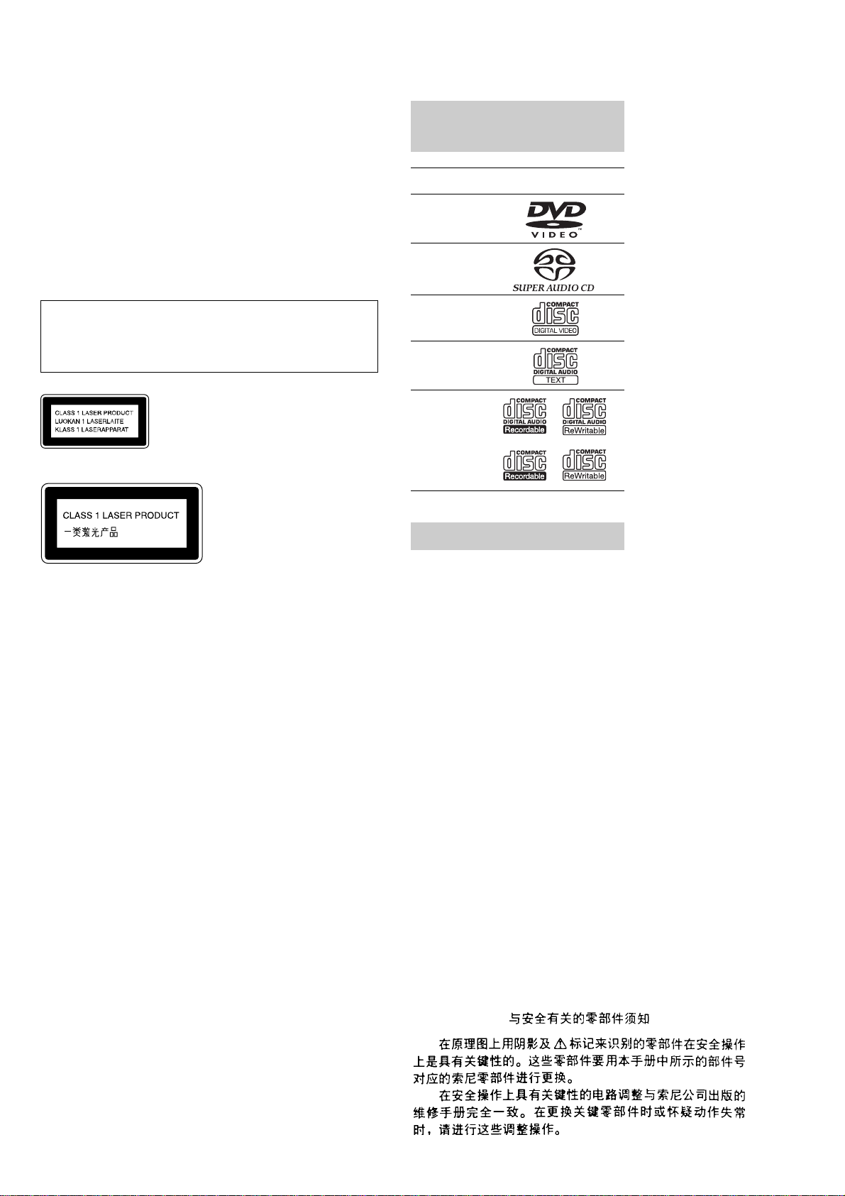
This System Can Play the
Following Discs
Format of
discs
Disc logo
DVD VIDEO
Super Audio
CD
VIDEO CD
Audio CD
CD-R/CD-RW
(audio data)
(MP3 files)
(JPEG files)
Terms for Discs
3
HCD-SB300
Note on PBC (Playback Control)
(VIDEO CDs)
This system conforms to Ver. 1.1 and Ver. 2.0 of
VIDEO CD standards. You can enjoy two kinds
of playback depending on the disc type.
About Multi Session CD
•This system can play Multi Session CDs when
an MP3 audio track is contained in the first
session. Any subsequent MP3 audio tracks
recorded in later sessions can also be played
back.
•This system can play Multi Session CDs when
a JPEG image file is contained in the first
session. Any subsequent JPEG image files
recorded in later sessions can also be played
back.
• If audio tracks and images in music CD format
or video CD format are recorded in the first
session, only the first session will be played
back.
Region code
Your system has a region code printed on the
back of the unit and will only play DVDs labeled
with the same region code.
DVDs labeled will also play on this system.
If you try to play any other DVD, the message
[Playback prohibited by area limitations.] will
appear on the TV screen. Depending on the
DVD, no region code indication may be given
even though playing the DVD is prohibited by
area restrictions.
Examples of discs that the
system cannot play
The system cannot play the following discs:
•CD-ROMs (except for extension “.MP3,”
“.JPG,” or “.JPEG”)
•CD-Rs/CD-RWs other than those recorded in
the following formats:
–audio CD format
–video CD format
–MP3/JPEG format that conforms to
ISO9660* Level 1/Level 2, or its extended
format, Joliet
•Data part of CD-Extras
•DVD-ROMs
•DVD Audio discs
•DVD-RAMs
•DVD-RWs in VR (Video Recording) mode
•Progressive JPEG file
*A logical format of files and folders on CD-ROMs,
defined by ISO (International Organization for
Standardization)
Do not load the following discs:
•A DVD with a different region code.
•A disc that is neither standard nor circular
(e.g., card, heart, or star shape).
•A disc with paper or stickers on it.
•A disc that has adhesive or cellophane tape still
left on it.
Disc type You can
VIDEO CDs
without PBC
functions
(Ver. 1.1 discs)
Enjoy video playback (moving
pictures) as well as music.
VIDEO CDs
with PBC
functions
(Ver. 2.0 discs)
Play interactive software using
menu screens displayed on the
TV screen (PBC Playback), in
addition to the video playback
functions of Ver. 1.1 discs.
Moreover, you can play high-
resolution still pictures, if they
are included on the disc.
DVD
structure
VIDEO CD,
Super
Audio CD
or CD
structure
MP3
structure
Disc
Disc
Disc
Title
Chapter
Track
Index
Album
Track
JPEG
structure
Disc
Album
File
ALL
Notes about CD-R/CD-RW/DVD-R/DVD-RW
(Video mode)/DVD+R/DVD+RW
In some cases, CD-R/CD-RW/DVD-R/DVD-RW
(Video mode)/DVD+R/DVD+RW cannot be played
on this player due to the recording quality or physical
condition of the disc, or the characteristics of the
recording device and authoring software.
The disc will not play if it has not been correctly
finalized. For more information, see the operating
instructions for the recording device.
Note that discs created in the Packet Write format
cannot be played.
Music discs encoded with copyright
protection technologies
This product is designed to play back discs that
conform to the Compact Disc (CD) standard.
Recently, various music discs encoded with copyright
protection technologies are marketed by some record
companies. Please be aware that among those discs,
there are some that do not conform to the CD standard
and may not be playable by this product.
Note on playback operations
of DVDs and VIDEO CDs
Some playback operations of DVDs and VIDEO
CDs may be intentionally set by software
producers. Since this system plays DVDs and
VIDEO CDs according to the disc contents the
software producers designed, some playback
features may not be available. Also, refer to the
instructions supplied with the DVDs or VIDEO
CDs.
Copyrights
This product incorporates copyright protection
technology that is protected by U.S. patents and
other intellectual property rights. Use of this
copyright protection technology must be
authorized by Macrovision, and is intended for
home and other limited viewing uses only unless
otherwise authorized by Macrovision. Reverse
engineering or disassembly is prohibited.
This system incorporates with Dolby* Digital
and Dolby Pro Logic (II) adaptive matrix
surround decoder and the DTS** Digital
Surround System.
*Manufactured under license from Dolby
Laboratories.
“Dolby”, “Pro Logic”, and the double-D symbol are
trademarks of Dolby Laboratories.
**Manufactured under license from Digital Theater
Systems, Inc.
“DTS” and “DTS Digital Surround” are trademarks
of Digital Theater Systems, Inc.
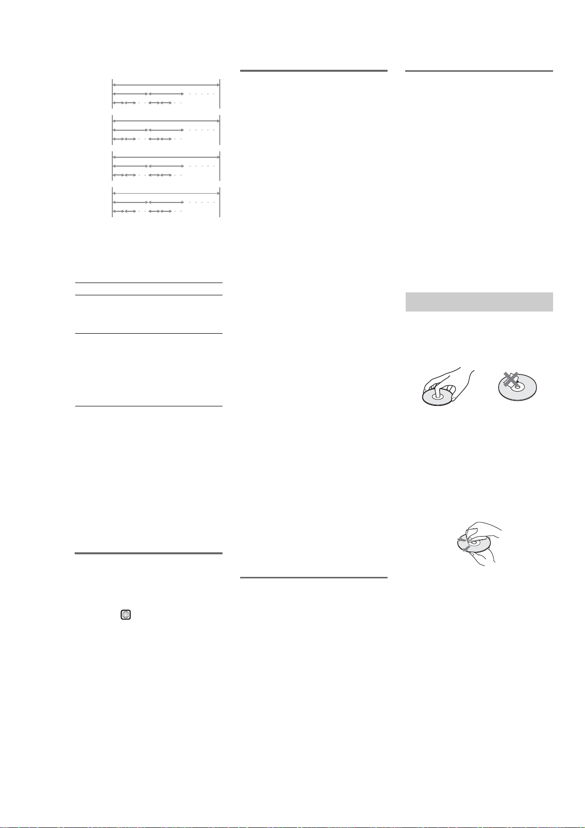
On handling discs
•To keep the disc clean, handle the disc by its
edge. Do not touch the surface.
•Do not stick paper or tape on the disc.
•Do not expose the disc to direct sunlight or
heat sources such as hot air ducts, or leave it in
a car parked in direct sunlight as the
temperature may rise considerably inside the
car.
•After playing, store the disc in its case.
On cleaning
•Before playing, clean the disc with a cleaning
cloth.
Wipe the disc from the center out.
•Do not use solvents such as benzine, thinner,
commercially available cleaners, or anti-static
spray intended for vinyl LPs.
This system can only play back a standard
circular disc. Using neither standard nor circular
discs (e.g., card, heart, or star shape) may cause
a malfunction.
Do not use a disc that has a commercially
available accessory attached, such as a label or
ring.
Notes about the Discs

4
HCD-SB300
TABLE OF CONTENTS
1. SERVICING NOTES ............................................... 5
2. GENERAL ................................................................... 7
3. DISASSEMBLY
3-1. Disassembly Flow ........................................................... 9
3-2. Case ................................................................................. 9
3-3. Front Panel Block ............................................................ 10
3-4. DVD Mechanism Deck ................................................... 10
3-5. IO Board.......................................................................... 11
3-6. MAIN Board.................................................................... 11
3-7. Tray (AU) ........................................................................ 12
3-8. Optical Pick-up Block, Chuck Cam ................................ 12
3-9. Optical Traverse Unit (DBU-1) ....................................... 13
3-10. DC Motor (Loading) (M001) .......................................... 13
4. TEST MODE.............................................................. 14
5. ELECTRICAL ADJUSTMENTS ......................... 23
6. DIAGRAMS
6-1. Block Diagram – RF SERVO Section – ......................... 24
6-2. Block Diagram – DVD DSP Section – ........................... 25
6-3. Block Diagram – AUDIO Section – ............................... 26
6-4. Block Diagram – AMP, PANEL Section – ..................... 27
6-5. Block Diagram – POWER SUPPLY Section – .............. 28
6-6. Printed Wiring Board – RF Board –............................... 30
6-7. Schematic Diagram – RF Board –.................................. 31
6-8. Printed Wiring Board
– DMB07 Board (Component Side) –............................. 32
6-9. Printed Wiring Board
– DMB07 Board (Conductor Side) – .............................. 33
6-10. Schematic Diagram – DMB07 Board (1/9) –................. 34
6-11. Schematic Diagram – DMB07 Board (2/9) –................. 35
6-12. Schematic Diagram – DMB07 Board (3/9) –................. 36
6-13. Schematic Diagram – DMB07 Board (4/9) –................. 37
6-14. Schematic Diagram – DMB07 Board (5/9) –................. 38
6-15. Schematic Diagram – DMB07 Board (6/9) –................. 39
6-16. Schematic Diagram – DMB07 Board (7/9) –................. 40
6-17. Schematic Diagram – DMB07 Board (8/9) –................. 41
6-18. Schematic Diagram – DMB07 Board (9/9) –................. 42
6-19. Printed Wiring Board – IO Board –................................ 44
6-20. Schematic Diagaram – IO Board –................................. 45
6-21. Printed W iring Board
– AMP Board (Component Side) – ................................. 46
6-22. Printed W iring Board
– AMP Board (Conductor Side) – ................................... 47
6-23. Schematic Diagaram – AMP Board (1/4)....................... 48
6-24. Schematic Diagaram – AMP Board (2/4)....................... 49
6-25. Schematic Diagaram – AMP Board (3/4)....................... 50
6-26. Schematic Diagaram – AMP Board (4/4)....................... 51
6-27. Printed Wiring Board – SPK Board – ............................ 52
6-28. Schematic Diagram – SPK Board – ............................... 53
6-29. Printed W iring Boards
– MAIN Section (Component Side) – ............................. 54
6-30. Printed W iring Boards
– MAIN Section (Conductor Side) –............................... 55
6-31. Schematic Diagram – MAIN Section (1/2) –................. 56
6-32. Schematic Diagram – MAIN Section (2/2) –................. 57
6-33. Printed Wiring Boards – PANEL Section – .................... 58
6-34. Schematic Diagaram – PANEL Section – ...................... 59
6-35. Printed Wiring Board – FL Board – ............................... 60
6-36. Schematic Diagram – FL Board –.................................. 61
6-37. Printed Wiring Boards – POWER SUPPLY Section...... 62
6-38. Schematic Diagarm – POWER SUPPLY Section – ....... 63
7. EXPLODED VIEWS
7-1. Front Panel Section ......................................................... 84
7-2. Back Panel Section .......................................................... 85
7-3. Chassis Section................................................................ 86
7-4. DVD Mechanism Deck Section (CDM77A-DVBU20) .. 87
8. ELECTRICAL PARTS LIST................................ 88
5
HCD-SB300
SECTION 1
SERVICING NOTES
NOTES ON HANDLING THE OPTICAL PICK-UP
BLOCK OR BASE UNIT
The laser diode in the optical pick-up block may suffer electrostatic
break-down because of the potential difference generated by the
charged electrostatic load, etc. on clothing and the human body.
During repair, pay attention to electrostatic break-down and also
use the procedure in the printed matter which is included in the
repair parts.
The flexible board is easily damaged and should be handled with
care.
NOTES ON LASER DIODE EMISSION CHECK
The laser beam on this model is concentrated so as to be focused on
the disc reflective surface by the objective lens in the optical pick-
up block. Therefore, when checking the laser diode emission,
observe from more than 30 cm away from the objective lens.
UNLEADED SOLDER
Boards requiring use of unleaded solder are printed with the lead-
free mark (LF) indicating the solder contains no lead.
(Caution: Some printed circuit boards may not come printed with
the lead free mark due to their particular size)
: LEAD FREE MARK
Unleaded solder has the following characteristics.
• Unleaded solder melts at a temperature about 40 °C higher
than ordinary solder.
Ordinary soldering irons can be used but the iron tip has to be
applied to the solder joint for a slightly longer time.
Soldering irons using a temperature regulator should be set to
about 350 °C.
Caution: The printed pattern (copper foil) may peel away if
the heated tip is applied for too long, so be careful!
• Strong viscosity
Unleaded solder is more viscou-s (sticky, less prone to flow)
than ordinary solder so use caution not to let solder bridges
occur such as on IC pins, etc.
• Usable with ordinary solder
It is best to use only unleaded solder but unleaded solder may
also be added to ordinary solder.
RELEASING THE DISC TRAY LOCK
The disc tray lock function for the antitheft of an demonstration
disc in the store is equipped.
Releasing Procedure :
Press two buttons of
A and x simultaneously for five seconds.
The message “UNLOCKED” is displayed and the tray is unlocked.
Note: When “LOCKED” is displayed, the tray lock is not released by turning
power on/off with the I/1 button.
NOTE OF REPLACING THE DMB07 BOARD
When replacing the DMB07 board, since the adjustment value is
not set up correctly, “Drive Auto Adjustment” can’t be performed.
In this case, initialize Memory in the following procedures.
Procedure:
1. Set the test mode. (See page 24)
2. Press the [2] ke y of the remote commander, and set the “DRIVE
MANUAL OPERATION”. (See page 28)
3. Press the [6] key of the remote commander, and set the “2-6,
Memory Check”. (See page 30)
4. Press the [CLEAR] key of the remote commander , and initialize
Memory.
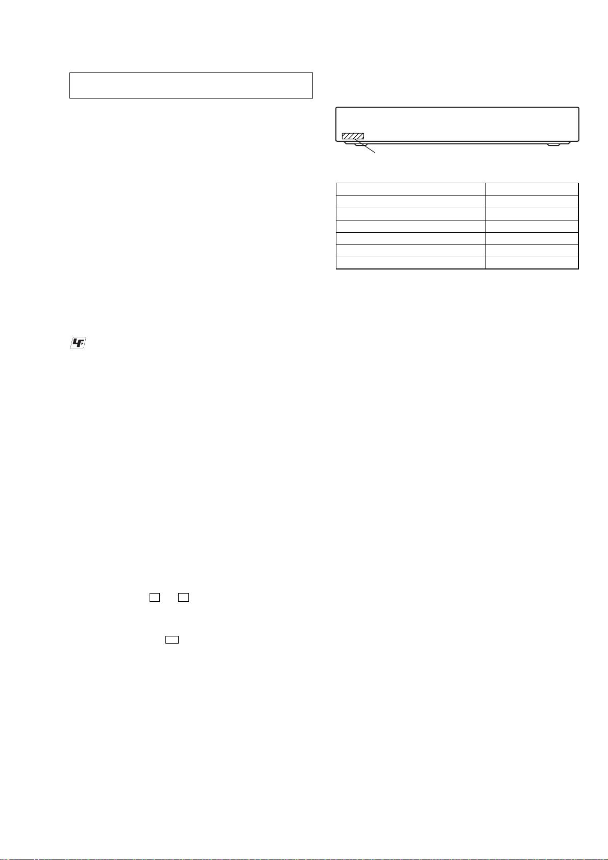
• MODEL IDENTIFICATION
MODEL PART No.
AEP, UK models 4-253-346-0[]
Russian model 4-253-346-1[]
Saudi Arabia model 4-253-346-2[]
Singapore model 4-253-346-3[]
Korean and Chinese models 4-253-346-4[]
Australian model 4-253-346-5[]
PART No.
– Back Panel –
6
HCD-SB300
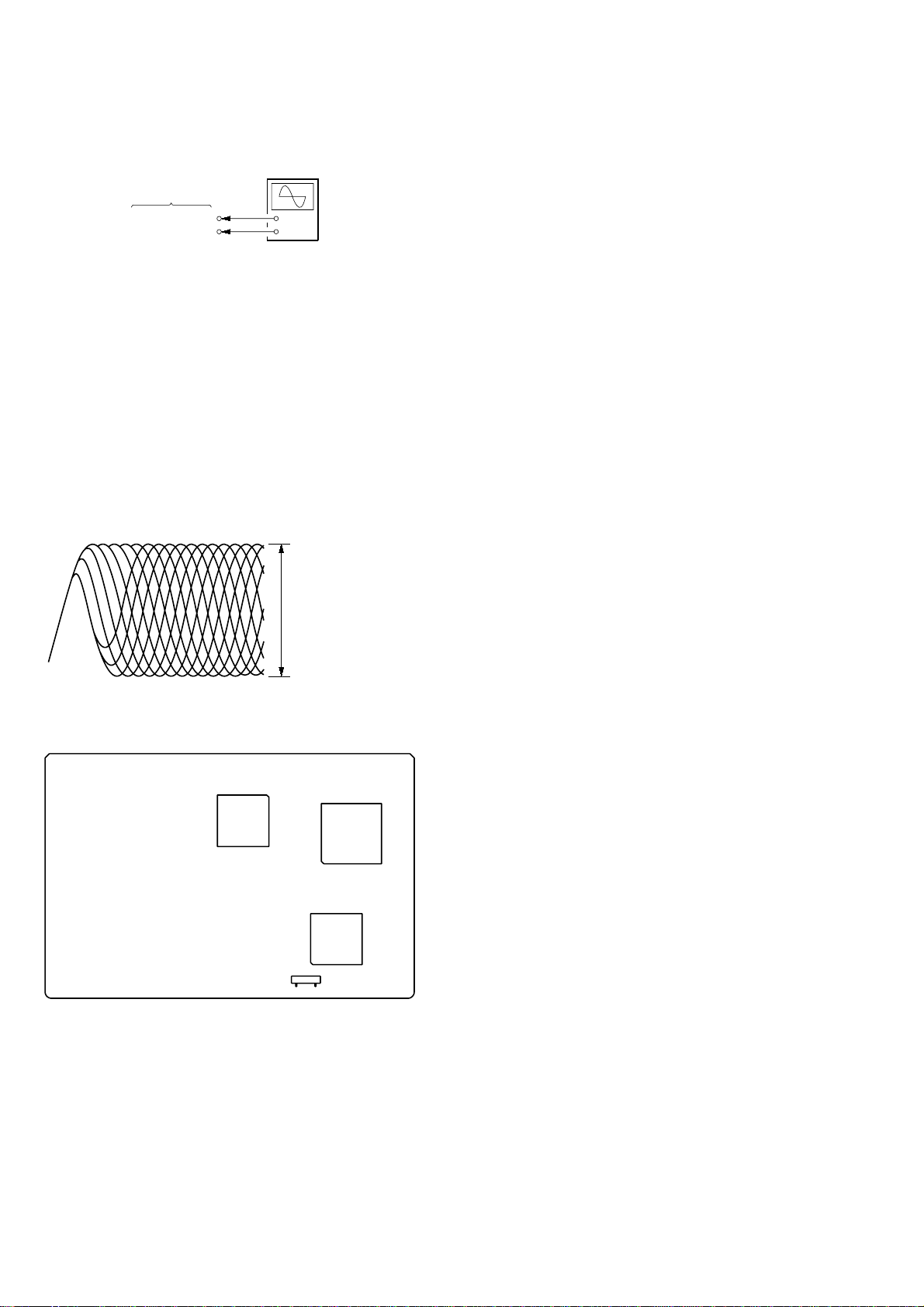
DECISION TO PASS OR FAIL OF THE OPTICAL
PICK-UP BLOCK
Connection:
Procedure:
1. Connect an oscilloscope to test point 1 pin and 3 pin of
CN901 on the DMB07 board.
2. Turn the power on.
3. Put the disc (LUV-P01) (Part No.: 4-999-032-01) (CD) in to
playback.
4. Confirm that oscilloscope waveform is clear and check RF
signal level is correct or not.
5. Put the disc (TDV -520CSO) (P art No.: J-2501-236-A) (DVD)
is to playback.
6. Perform confirmation in the same manner as step 4.
Note: A clear RF signal waveform means that the shape “◊” can be clearly
distinguished at the center of the waveform.
Checking Location:
DMB07 board
CN901
1
pin
CN901
3
pin
+
–
oscilloscope
VOLT/DIV: 200 mV
TIME/DIV: 500 ns
CD: 1.05
±
0.2 Vp-p
DVD: 1.09
±
0.2 Vp-p
RF signal waveform
– DMB07 Board (Component Side) –
CN901
IC701
IC207
IC801
1
7
7
HCD-SB300
SECTION 2
GENERAL
This section is extracted from
instruction manual.
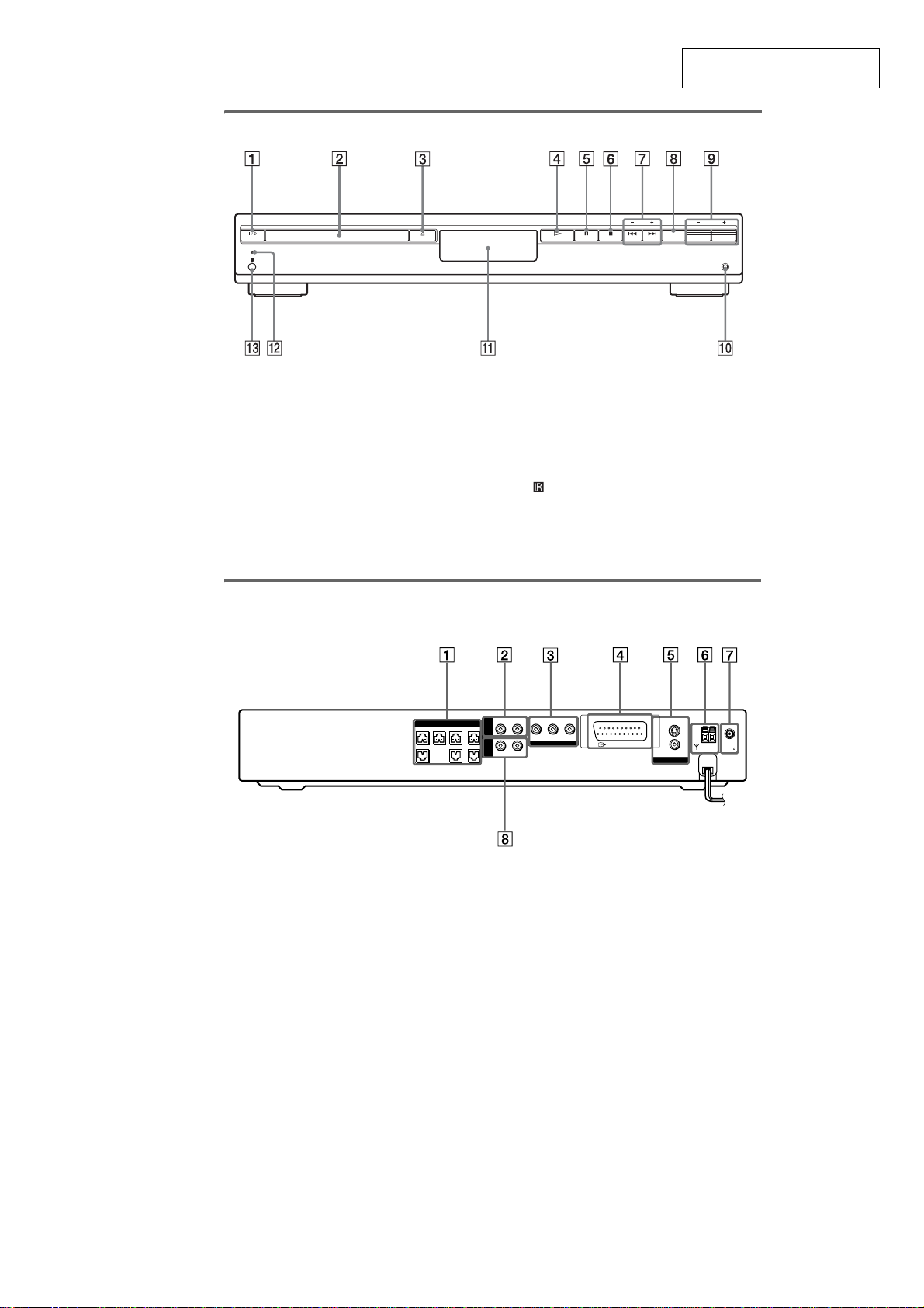
Front Panel
A "/1 (power)
B Disc tray
C A (open/close)
D H (play)
E X (pause)
F x (stop)
G ./>, PRESET –/+
H FUNCTION
I VOLUME –/+
J PHONES jack
K Front panel display
L STANDBY indicator
M (remote sensor)
STANDBY
PHONES
VOLUME
PRESET
FUNCTION
Rear Panel
A SPEAKER jacks
B VIDEO AUDIO IN L/R jacks
C COMPONENT VIDEO OUT jacks
(except AEP, UK models)
(AEP, UK models)
E MONITOR OUT (VIDEO/S VIDEO) jacks
(except AEP, UK models)
F AM terminals
G FM 75Ω COAXIAL jack
H SAT AUDIO IN L/R jacks
FRONT L
WOOFERSURR L
CENTER WOOFER
SPEAKER
MONITOR OUT
COMPONENT VIDEO OUT
FRONT R
SURR R
AUDIO IN
L
YP
B
/C
B
P
R
/C
R
VIDEO
S VIDEO (DVD ONLY)
R
AUDIO IN
L
R
VIDEO
SAT
COAXIAL
AM
FM
75
OUTPUT(TO TV)
EURO AV
D EURO AV OUTPUT (TO TV) jack
8
HCD-SB300
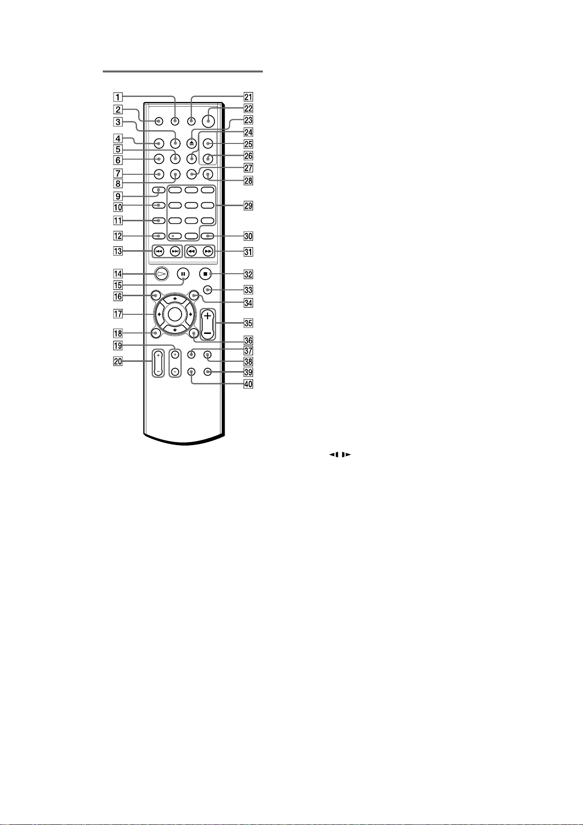
Remote
A SONY TV DIRECT
B SLEEP
C TUNER/BAND
D MUTING
E TUNER MENU
F PLAY MODE
G REPEAT
H FM MODE
I TV
J AUDIO
K ANGLE
L SUBTITLE
M ./>, PRESET –/+
N H PLAY
O X PAUSE
P DVD TOP MENU/ALBUM–
Q C/X/x/c/ENTER
R DVD DISPLAY
S TV CH +/–
T TV VOL +/–
U TV [/1 (on/standby)
V "/1 (standby)
W Z (open/close)
X DSGX
Y AUTO FORMAT DIRECT
Z MODE
wj NIGHT MODE
wk FUNCTION
wl Number buttons
e; ENTER
ez m/M// SLOW, TUNING –/+
es x STOP
ed DISPLAY
ef DVD MENU/ALBUM+
eg VOLUME +/–
eh O RETURN
ej TV/VIDEO
ek CLEAR
el DIMMER
r; DVD SETUP
123
45
8
0
6
7
10
9
HCD-SB300
9
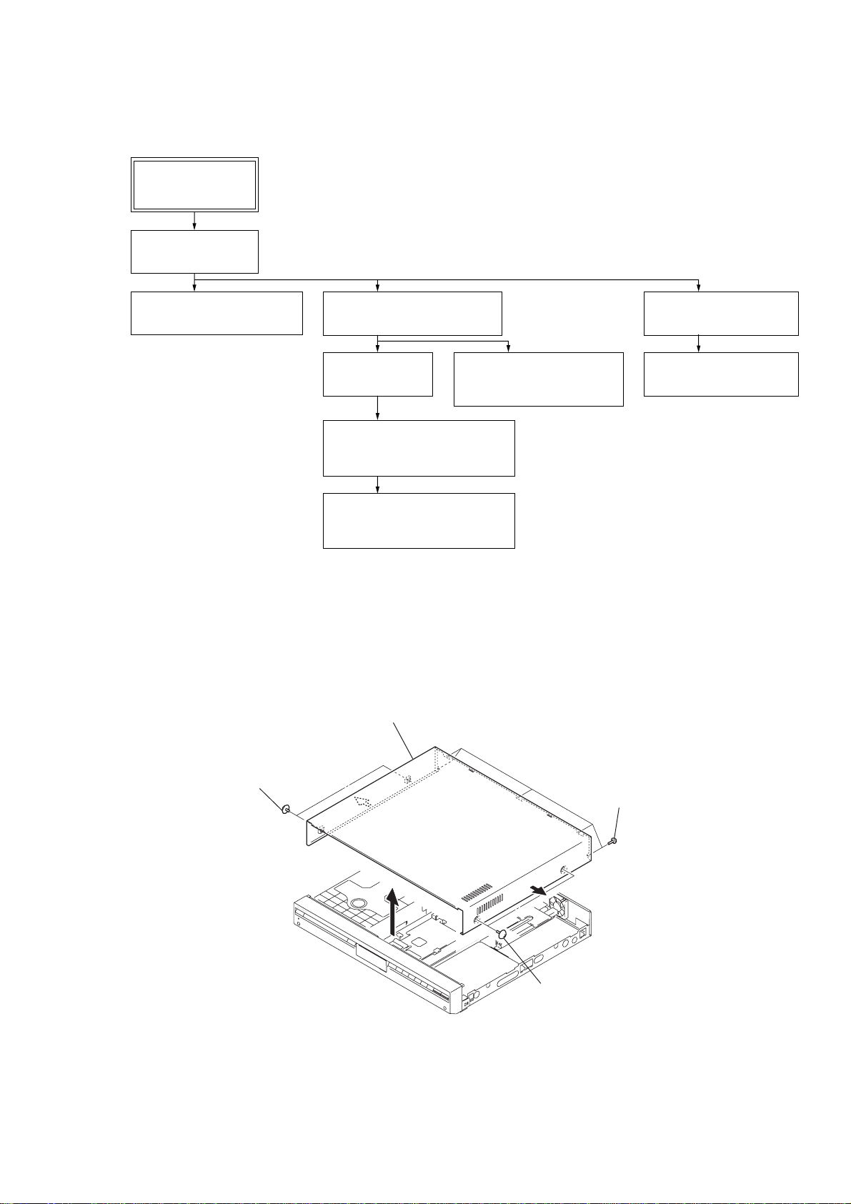
Note: Follow the disassembly procedure in the numerical order given.
3-2. CASE
• This set can be disassembled in the order shown below.
3-1. DISASSEMBLY FLOW
SECTION 3
DISASSEMBLY
SET
3-2. CASE
(Page 9)
3-4. DVD MECHANISM DECK
(Page 10)
3-7. TRAY (AU)
(Page 12)
3-9. OPTICAL TRAVERSE UNIT
(DBU-1)
(Page 13)
3-8. OPTICAL PICK-UP BLOCK,
CHUCK CAM
(Page 12)
3-10. DC MOTOR (LOADING)
(M001)
(Page 13)
3-3. FRONT PANEL BLOCK
(Page 10)
3-5. IO BOARD
(Page 11)
3-6. MAIN BOARD
(Page 11)
2
two screws
(CASE3 TP2)
4
case
3
five screws
(BVTP 3
×
8
)
1
two screws
(CASE3 TP2)
HCD-SB300
10
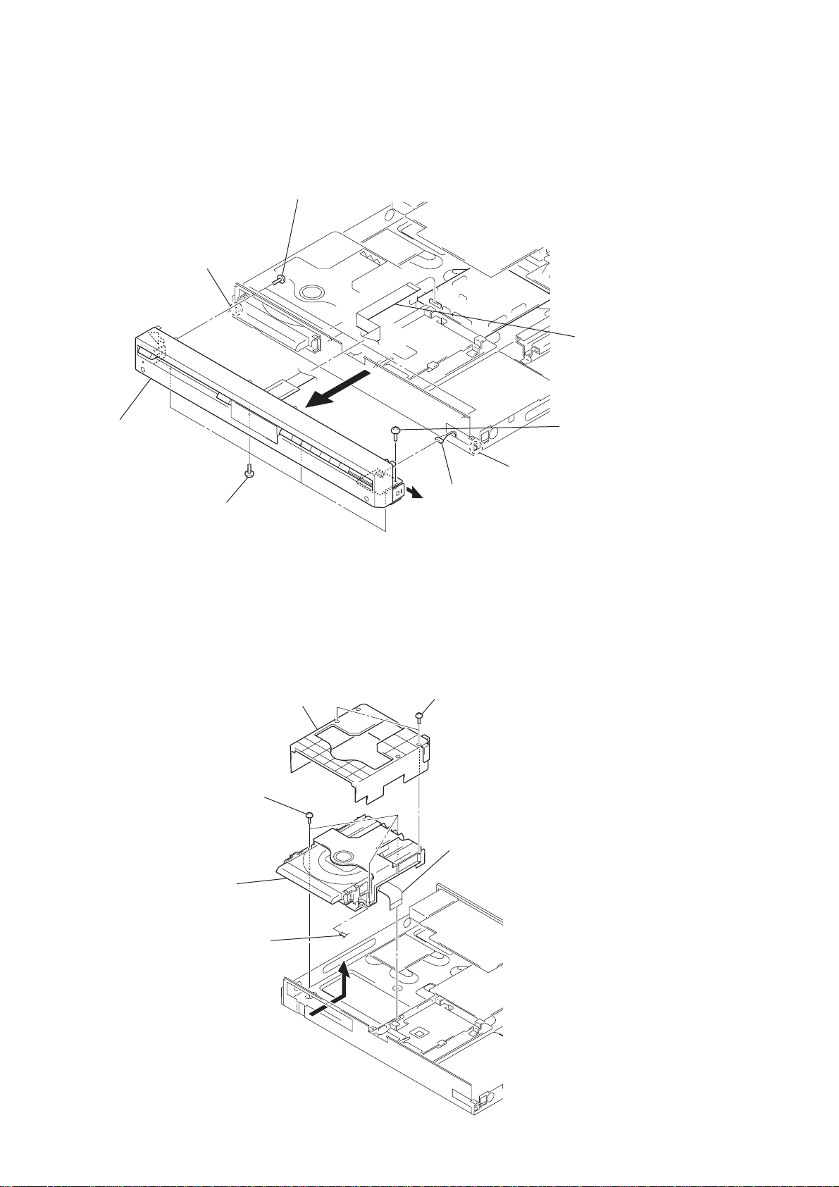
3-3. FRONT PANEL BLOCK
3-4. DVD MECHANISM DECK
2
four screws
(DIA. 2.6
×
8)
5
claw
8
front panel
block
4
four screws
(BV3)
6
7
connector
(CN04)
5
claw
3
screw
(BV3)
1
wire (flat type)
(19 core) (CN503)
2
cover (DVD)
4
three screws
(BV3)
5
DVD mechanism
deck
3
wire (flat type)
(5 core) (CN001)
3
wire (flat type)
(29 core) (CN501)
1
two screws
(IT3B)
HCD-SB300
11
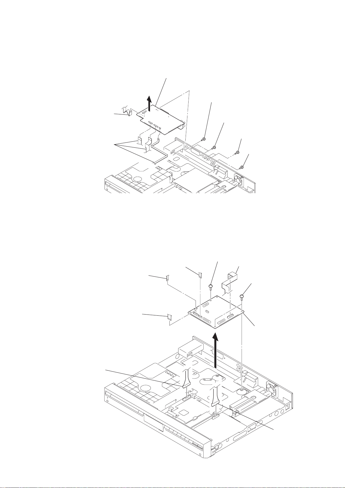
3-5. IO BOARD
3-6. MAIN BOARD
2
screw (DIA. 2.6
×
8)
(except AEP, UK, RU)
2
two screws (BV3)
(AEP, UK, RU)
2
two screws (BV3)
(except AEP, UK, RU)
1
screw (BV3)
4
three wires (flat type)
(17 core: CN201,
15 core: CN202,
5 core: CN203)
4
wire (flat type)
(11 core) (CN200)
3
5
IO board
1
wire (flat type)
(9 core) (CN505)
1
wire (flat type)
(5 core) (CN511)
1
wire (flat type)
(19 core) (CN503)
2
connector
(CN102)
3
screw
(BV3)
1
wire (flat type)
(17 core) (CN509)
4
two screws
(BV3)
5
MAIN board
2
connecto
r
(CN8)
• Abbreviation
RU: Russian model
HCD-SB300
12
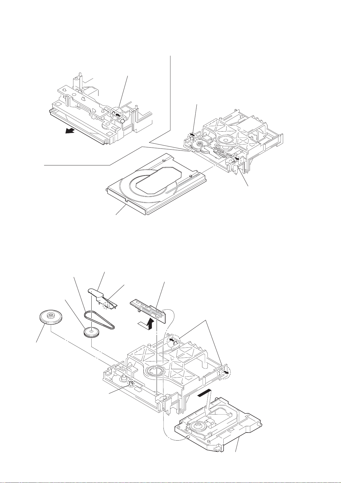
3-7. TRAY (AU)
3-8. OPTICAL PICK-UP BLOCK, CHUCK CAM
4
tray (AU)
3
claw
3
claw
1
Slide the chuck
cam in the direction
of arrow
A
.
A
2
6
gear
4
claw
5
pulley
3
belt
2
support
1
claw
9
chuck cam
7
two claws
8
optical pick-up bloc
k
HCD-SB300
13
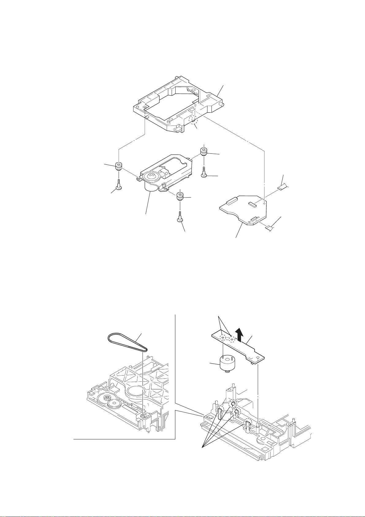
3-9. OPTICAL TRAVERSE UNIT (DBU-1)
3-10. DC MOTOR (LOADING) (M001)
3
w
ire (flat type)
(24 core) (CN001)
2
flexible board
(CN003)
5
step screw (M)
5
step screw (M)
5
step screw (M)
8
optical traverse unit
(DBU-1)
1
claw
6
holder (DBU1)
7
insulator
7
insulator
7
insulator
4
RF board
1
belt
2
four claws
3
MS-128 board
4
Remove two solders.
5
DC motor
(loading)
(M001)

14
HCD-SB300
COLD RESET
The cold reset clears all data including preset data stored in the
RAM to initial conditions. Execute this mode when returning the
set to the customer.
Procedure:
1. Press three buttons of the > , X , and A simultaneously.
2. The message “ColdRESET” is displayed on the fluorescent
indicator tube, and the set is reset, then becomes standby mode.
VERSION DISPLAY
This mode is used to check the model and software version.
Procedure:
1. Press the I/1 button to turn the power on.
2. Press three b uttons of the [VOL +], VOL – and A simultaneously for
five seconds. The software version and destination is displayed.
DISPLAY LED TEST
This mode is used to check the fluorescent indicator tube and FL
back light LED.
Procedure:
1. Press three buttons of the VOL – , . and A simultaneously.
2. All segments of fluorescent indicator tube and FL back light
LED are turned ON.
3. To release from this mode, press the I/1 button.
AUTO TUNING
This mode is used to auto tuning.
Procedure:
1. Press two buttons of the . and > simultaneously for
three seconds.
2. The message “AUTO 87.50” is displayed on the fluorescent
indicator tube. Then display repeats from automatic “AUTO
87.50” to “AUTO 108.00”.
3. To release from this mode, press the any buttons except the
VOLUME +/– buttons.
AMP TEST
This mode is used to check the function of the amplifier.
Procedure:
1. Press three buttons of the VOL – , . and [FUNCTION]
simultaneously.
2. Each time the [AUTO FORMAT] or [MODE] key on the remote
commander is pressed, output change as following order.
3. Each time the [DSGX] key on the remote commander is pressed,
DSGX on/off are changed over.
4. Each time the [NIGHT MODE] key on the remote commander
is pressed, NIGHT MODE on/off are changed over.
5. Each time the VOLUME +/– key on the remote commander is
pressed, the message “VOLUME MIN”, “VOLUME 21” or
“VOLUME MAX” is displayed in this order on the fluorescent
indicator tube.
6. To release from this mode, press the I/1 button.
KEY TEST
This mode is used to check the front panel keys.
Procedure:
1. Press three buttons of the VOL – , [VOL +] and [FUNCTION]
simultaneously.
2. the fluorescent indicator tube displays “KEY XX”. Each time
a button is pressed, “KEY” value increases.
However, once a button is pressed, it is no longer taken into
account.
3. To release from this mode, perform same manner as step 1.
ROBBERY PREVENTION LOCK
This mode is used to unable to take sample disc out of set in the
shop.
Procedure:
1. Press the I/1 button to turn the power on.
2. Press the [FUNCTION] button to select “DVD”.
3. Press two buttons of the x and A simultaneously for five
seconds.
4. The message “LOCKED” is displayed on the fluorescent
indicator tube and the disc tray is locked. (Even if pressing
the A button, the message “LOCKED” is displayed on the
liquid crystal display and the disc tray is locked)
5. To release from this mode, press two buttons of the x and
the A simultaneously for five seconds again.
6. The message “UNLOCKED” is displayed on the liquid crystal
display and the disc tray is unlocked.
SHIP MODE
This mode moves the optical pick-up to the position durable to
vibration. Use this mode when returning the set to the customer
after repair.
Procedure:
1. Press the I/1 button to turn the power on.
2. Press the [FUNCTION] button to select “DVD”.
3. Press three buttons the > , . and A simultaneously.
4. The message “MECHA LOCK” is displayed on the liquid
crystal display and the ship mode is set, then becomes power
off.
REPEAT 5 TIMES CANCEL
The number of repeat for DVD playback is 5 times when the repeat
mode is “REPEAT”. This mode enables DVD to repeat playback
for limitless times.
Procedure:
1. Press the I/1 button to turn the power on.
2. Press the [FUNCTION] button to select “DVD”.
3. Press three buttons of the > , [VOL +] and A simultaneously.
4. Repeat 5 times limit is canceled.
AM TUNING INTERVAL CHANGE-OVER
(Except AEP, UK, Russian models)
A step of AM channels can be changed o ver between 9 kHz and 10
kHz.
Procedure:
1. Press the I/1 button to turn the power on.
2. Press the [FUNCTION] button to select “AM”.
3. Press the I/1 button to turn the power off.
4. Press two buttons of the VOL – and I/1 simultaneously.
5. AM step 9 kHz and 10 kHz are changed over.
SECTION 4
TEST MODE
Display Function
SWAP F2S FRONT L-ch/R-ch input is outputted also
to SURROUND L-ch/R-ch speakers.
SWAP F2CW L-ch input is outputted to CENTER speaker,
and R-ch input is outputted to WOOFER
speaker.
SWAP Full L-ch/R-ch input is outputted all speakers.
EQ MAX 6dB of levels of the bus and treble is upped.
EQ MIN 6dB of levels of the b us and tr eble is do wned .
SRAH CHECK Not used
15
HCD-SB300
DVD DEBUG MODE
This mode is used to unable to reset for performing the debug of
DVD.
Procedure:
1. Press the I/1 button to turn the power on.
2. Press the [FUNCTION] button to select “DVD”.
3. Press three buttons of the > , [VOL +], and [FUNCTION]
simultaneously.
4. DVD debug mode is set.
COLOR SYSTEM CHANGE-OVER
(Saudi Arabia, Singapore, Australian and Chinese
models)
This mode is used to changed over color system.
Procedure:
1. Press the I/1 button to turn the power on.
2. Press the [FUNCTION] button to select “DVD”.
3. Press the I/1 button to turn the power off.
4. Press two buttons of X and I/1 simultaneously.
5. The message “COLOR NTSC” or “COLOR P AL” is displayed
on the liquid crystal display, and the color system is changed
over NTSC or PAL.
COMPULSION INTERLACE
This mode is used to changed over video output into interlace.
Procedure:
1. Press the I/1 button to turn the power on.
2. Press the [FUNCTION] button to select “DVD”.
3. Press two buttons of . and [FUNCTION] simultaneously.
4. Video output is changed over interlace.
VACS DISPLAY
This mode is used to display of VACS (Variable Attenuation Control
System) states.
Procedure:
1. Press the I/1 button to turn the power on.
2. Press three buttons of the x , [FUNCTION] and X
simultaneously.
3. When VACS is on, “VACS O” is displayed. When VACS is
off, “VACS OFF” is displayed.
VACS ON/OFF
This mode is used to switch on or off the V A CS (Variable Attenuation
Control System).
Procedure:
1. Press the I/1 button to turn the power on.
2. Press three buttons of the > , [FUNCTION] and X
simultaneously.
3. VACS on/off are changed over.
PRODUCT OUT
This mode is used to performed COLD RESET and SHIP MODE
simultaneously.
Procedure:
1. Press the three buttons of the x , . , and [FUNCTION]
simultaneously.
2. The message “ColdRESET” is displayed on the fluorescent
indicator tube, and the set is reset, then becomes standby mode.
DVD SECTION
DVD TEST MODE GENERAL DESCRIPTION
The T est Mode allows you to make diagnosis and adjustment easily
using the remote commander and monitor TV. The instructions,
diagnostic results, etc. are given on the on-screen display (OSD).
• Test Disc List
Use the following test disc on test mode.
TDV-520CSO (DVD-SL): Part No. J-2501-236-A
LUV-P01 (CD) : Part No. 4-999-032-01
TDV-540C (DVD-DL) : Part No. J-2501-235-A
Note: Do not use existing test disc for DVD.
STARTING DVD TEST MODE
1. Press the I/1 button to turn the power ON.
2. Press the [FUNCTION] button to select “DVD”.
4. Press three buttons of the x , A and [VOLUME +]
simultaneously.
5. The message “SERVICE IN” is displayed on the fruorescent
indicator tube, and the Test Mode Menu is displayed on the
monitor screen as follows. (At the bottom of the menu screen,
the model name and revision number are displayed)
Test Mode Menu
0. Syscon Diagnosis
1. Drive Auto Adjustment
2. Drive Manual Operation
3. Mecha Aging
4. Emergency History
5. Mecha Error History
6. Version Information
7. Video Level Adjustment
Exit: POWER Key
Model :DAV-SB300
Revision :x.xx
6. To execute each function, select the desired menu and press
its number on the remote commander (RM-Z20016).
7. To release from test mode, press the I/1 button and turn the
power off.

16
HCD-SB300
OPERATING DVD TEST MODE
0. Syscon Diagnosis
The same contents as board detail check by serial interface can be
checked from the remote commander operation.
On the Test Mode Menu screen, press [0] key on the remote
commander, and the following Check Menu will be displayed.
### Syscon Diagnosis ###
Check Menu
0. Quit
1. All
2. Version
3. EEPROM
4. GPIO
5. SD Bus
6. Video
7. Audio
0-0. Quit
Quit the Syscon Diagnosis and return to the Test Mode Menu.
0-1. All (All items continuous check)
This menu checks all diagnostic items continuously. Normally, all
items are checked successively one after another automatically
unless an error is found, but at a certain item that requires judgment
through a visual check to the result, the following screen is displayed
for the key entry.
Example display
### Syscon Diagnosis ###
Diag All Check
No.2 Version
2-2. Version
ROM Reversion = X.XX
Press NEXT Key to Continue
Press PREV Key to Repeat
For the ROM check, the check sum calculated by the syscon is
output, and therefore you must compare it with the specified value
for confirmation.
Following the message, press the > button to go to the next item,
or press the . button to repeat the same operation again.
To quit the diagnosis and return to Check Menu screen, press the
[RETURN] key on the remote commander to display Check Menu.
• Error occurred
If an error occurred, the diagnosis is suspended and error is displayed.
Press the [RETURN] key on the remote commander to quit the
diagnosis, or press the . button to repeat the same check where
an error occurred, or press the > button to continue the check
from the item next to faulty item.
General Description of Checking Method
Selecting 2 and subsequent items calls the submenu screen of each
item. And selecting 2 and subsequent items executes respective
menus and outputs the results.
For the contents of each submenu, see “Check Items List” as below .
Check Items List:
0-2. Version
0-2-1. All
0-2-2. Version
0-2-3. ROM Check Sum
0-2-4. Model Type
0-2-5. Region
0-3. EEPROM Check
0-3-1. Sampling Check
0-3-2. Detail Check
0-4. GP I/O Check
0-5. SD Bus Check
0-6. Video Check
0-7. Audio Check
0-2. Version
0-2-2. Version
The revision number of ROM (IC204) that the program for
the DVD system processor (IC207) is stored.
(4 digits hexadecimal number)
0-2-3. ROM Check Sum
The revision number of ROM (IC204) tha t the program for
the DVD system processor (IC207) is stored.
0-2-4. Model Type
Model name is displayed.
0-2-5. Region
Model destination code is displayed. (2 digits number)
0-3. EEPROM Check
0-3-1. Sampling Check
EEPROM check at every 64 words.
It compares read data with write data of each address. When
there are discrepancies between two data, it displays error.
0-3-1. Detail Check
EEPROM check at every 1 word.
It compares read data with write data of each address. When
there are discrepancies between two data, it displays error .
0-4. GP I/O Check
Pull up/down setting check of the DVD system processor (IC207)
pin 150, 151 and 154 (for clock setting port).
0-5. SD Bus Check
SD bus data check between DVD decoder (IC701) and MPEG
decoder (IC207).
0-6. Video Check
Output the color bars for video level adjustment.
0-7. Audio Check
Output the test signal (1kHz sine wave) for 2 CH test.

17
HCD-SB300
1. Drive Auto Adjustment
On the Test Mode Menu screen, press the [1] key on the remote
commander, and the Adjustment Menu will be displayed.
## Drive Auto Adjustment ##
Adjustment Menu
0. ALL
1. DVD-SL
2. CD
3. DVD-DL
Exit: RETURN
Normally, [0] is selected to adjust DVD (single layer), CD and D VD
(dual layer) in this order. But, individual items can be adjusted for
the case where adjustment is suspended due to an error. In this mode,
the adjustment can be made easily through the operation following
the message displayed on the screen.
The disc used for adjustment must be the one specified for
adjustment.
1-0. ALL
Press the [0] key on the remote commander, and the servo set data
in EEPROM will be initialized. Then, 1. DVD-SL disc, 2. CD disc
and 3. DVD-DL disc are adjusted in this order.
Each time one disc was adjusted, it is ejected. Replace it with the
specified disc following the message. You can f inish the adjustment
by pressing the [RETURN] button on the remote commander.
Note: During adjustment of each disc, the measurement for disc type
judgment is made. As automatic adjustment does not judge the disc
type unlike conventional models, take care not to insert wrong type
discs. Also, do not give a shock during adjustment.
1-1. DVD-SL (single layer)
Press the [1] key on the r emote commander and insert a DVD single
layer disc following the message. Then the adjustment will be made
through the steps, then adjusted values will be written to the
EEPROM.
DVD Single Layer Disc Adjustment Steps:
1. Sled reset
2. Disc check memory SL
3. Wait 300 msec
4. Set disc type SL
5. LD on
6. Spindle start
7. Wait 1 sec
8. Focus servo on 0
9. Auto track offset adjust
10. CLVA on
11. Wait 500 msec
12. Tracking on
13. Wait 1 sec
14. Sled on
15. Check CLV on
16. Auto focus offset adjust
17. Auto focus gain adjust
18. Auto focus offset adjust
19. EQ boost adjust
20. Auto track gain adjust
21. All servo stop
22. EEP copy loop filter offset
1-2. CD
Press the [2] key on the remote commander and insert a CD disc
following the message. Then the adjustment will be made through
the steps, then adjusted values will be written to the EEPROM.
CD Adjustment Steps:
1. Sled rest
2. Disc check memory CD
3. Wait 500 msec
4. Set disc type CD
5. LD on
6. Spindle start
7. Wait 500 msec
8. Focus servo on 0
9. Auto track offset adjust
10. CLVA on
11. Wait 500 msec
12. Tracking on
13. (TC display start)
14. Wait 1 sec
15. Sled ON
16. Check CLV on
17. Auto focus offset adjust
18. Auto focus gain adjust
19. Auto focus offset adjust
20. EQ boost adjust
21. Auto track gain adjust
22. All servo stop

18
HCD-SB300
1-3. DVD-DL (dual layer)
Press the [3] key on the remote commander and insert a DVD dual
layer disc following the message. Then the adjustment will be made
through the steps, then adjusted values will be written to the
EEPROM.
DVD Dual Layer Disc Adjustment Steps:
1. Sled reset
2. Disc check memory DL
3. Wait 500 msec
4. Set disc type DL
5. LD on
6. Spindle start
7. Wait 1 sec
Layer 1 Adjust
8. Focus servo on 0
9. Auto track offset adjust
10. CLVA on
11. Wait 500 msec
12. Tracking on
13. Wait 500 msec
14. Sled on
15. Check CLV lock
16. Auto focus adjust
17. Auto focus gain adjust
18. Auto focus offset adjust
19. EQ boost adjust
20. Auto Track Gain Adjust
Layer 0 Adjust
21. Focus jump (L1 → L0)
22. Auto track offset adjust L0
23. CLVA on
24. Wait 500 msec
25. Tracking on
26. Wait 500 msec
27. Sled on
28. Check CLV lock
29. Auto Focus Adjust
30. Auto focus gain adjust
33. Auto focus offset adjust
34. EQ boost adjust
35. Auto track gain adjust
37. All servo stop
2. Drive Manual Operation
Note: This mode is used for design, and not used in service fundamentally.
On the Test Mode Menu screen, press the [2] key on the remote
commander, and the Operation Menu will be displayed. For the
manual operation, each servo on/off control and adjustment can be
executed manually.
## Drive Manual Operation ##
Operation Menu
1. Disc Type
2. Servo Control
3. Track/Layer Jump
4. Non EEPROM Write Adjust
5. EEPROM Write Adjust
6. Memory Check
7. Disc Check Memory
8. Error Rate Display
9. SACD Water Mark
Exit: RETURN
In using the manual operation menu, take care of the following
points. These commands do not provide protection, thus requiring
correct operation. The sector address or time code field is displayed
when a disc is loaded.
Note:
1. Set correctly the disc type to be used on the Disc Type screen.
2. In case of an alarm, exit the manual operation menu immediately
to stop the servo operation, and press the I/1 button to turn the
power off.
Basic operation:
(controllable from front panel or remote commander)
I/1 :Power off (release the test mode)
Z : Stop and eject/loading
[RETURN] : Return to Operation Menu or Test Mode Menu
. , > :Transition between sub modes of menu
[0] to [9] : Selection of menu items
Cursor o / O : Increase/Decrease in manually adjusted value

19
HCD-SB300
2-1. Disc Type
Disc Type
Disc Type Select
1. Disc Type Auto Check
2. Set Disc Type DVD
3. Set Disc Type CD
4. Set Disc Type Hybrid
Exit: RETURN
2-1-1. Disc Type Auto Check
1. Press the [1] key on the remote commander to display the Disc
Type Auto Check screen.
2. Insert a disc and press the [ENTER] key on the remote
commander.
3. It judges the type of inserted disc automatically and displays
the disc type and so on as below.
Disc Type Auto Check
Disc Type xx
Layer xx
Mirr Time xx
Mirr Count xx
FZC Count xx
PI Reference xx
PI Peak xx
ENTER.Execute
Exit: RETURN
Disc Type : CD, DVD or Hybrid (SACD)
Layer : SINGLE, DUAL or HYBRID
Mirr Time : Mirror time of between disc surface and record
surface when disc type judgment. (hexadecimal
number)
Mirr Count : The number of times which mirror counts between
disc surface and record surface when disc type
judging.
FZC Count : The number of times which focus zero cross points
of each layer when lens down.
PI Reference : The average of PI reference voltage. (hexadecimal
number)
PI Peak : PI peak level voltage. It performs only when disc
type judgment is successful. (hexadecimal number)
2-1-2. Disc T ype DVD
It sets up so that it may judge as a disc type of specification of the
disc with which the set was inserted.
[1]: DVD single layer disc (12 cm)
[2]: DVD dual layer disc (0 layer, 12 cm)
[3]: DVD dual layer disc (1 layer, 12 cm)
[4]: DVD-RW disc (12 cm)
[5]: DVD single layer disc (8 cm)
[6]: DVD dual layer disc (0 layer, 8 cm)
[7]: DVD dual layer disc (1 layer, 8 cm)
[8]: DVD-RW disc (8 cm)
2-1-3. Disc Type CD
It sets up so that it may judge as a disc type of specification of the
disc with which the set was inserted.
[1]: CD disc (normal speed, 12 cm)
[2]: CD disc (double speed, 12 cm)
[3]: CD disc (normal speed, 8 cm)
[4]: CD disc (double speed, 8 cm)
[5]: CD-RW disc (normal speed, 12 cm)
[6]: CD-RW disc (double speed, 12 cm)
[7]: CD-RW disc (normal speed, 8 cm)
[8]: CD-RW disc (double speed, 8 cm)
2-1-4. Disc Type Hybrid
It sets up so that it may judge as a disc type of specification of the
disc with which the set was inserted.
[1]: SACD Hybrid disc (SACD layer, 12 cm)
[2]: SACD Hybrid disc (CD layer, normal speed, 12 cm)
[3]: SACD Hybrid disc (CD layer, double speed, 12 cm)
[4]: SACD Hybrid disc (SACD layer, 8 cm)
[5]: SACD Hybrid disc (CD layer, normal speed, 8 cm)
[6]: SACD Hybrid disc (CD layer, double speed, 8 cm)
2-2. Servo Control
Note: Be sure to perform the disc type setup before performing this item.
Servo Control
1. LD off R.Sled FWD
2. Focus off L.Sled REV
3. SPDL off U.Sled Reset
4. CLVA off D.Sled Limit
5. Trk. off
6. Sled off
7. Fcs.Srch off
0. All Servo Off
Exit: RETURN
On this screen, the servo on/off control necessary for replay is
executed. Normally, turn on each servo from 1 sequentially and
when CLVA is turned on, the usual trace mode becomes active. In
the trace mode, DVD sector address or CD time code is displayed.
This is not displayed where the spindle is not locked.
The spindle could run overriding the control if the spindle system is
faulty or RF is not present. In such a case, do not operate CLVA.
[1] LD : Turn on/off the laser.
[2] Focus : Search the focus and turn on the focus.
[3] SPDL : Turn on/off the spindle.
[4] CLVA : Turn on/off normal servo of spindle servo.
[5] Trk. : Turn on/off the tracking servo.
[6] Sled : Turn on/off the sled servo.
[7] FCS. Srch : Turn on/off the focus search.
[0] : All servo off.
[R] Sled FWD (right cursor) : Move the sled forward.
[L] Sled REV (left cursor) : Move the sled reverse.
[U] Sled FWD (up cursor) : Reset the sled.
[D] Sled REV (down cursor) : Limit in the sled.

20
HCD-SB300
2-3. Track/Layer Jump
Track/Layer Jump
1. 1Tj FWD R.Lj L0>L1
2. 1Tj REV L.Lj L1>L0
3.500Tj Fine FWD U.Fj L0>L1
4.500Tj Fine REV D.Fj L1>L0
5.10kTj Dirc FWD
6.10kTj Dirc REV
7.20kTj Dirc FWD
8.20kTj Dirc REV
0.All Servo Off
Exit: RETURN
On this screen, track jump, etc. can be performed. Only for the DVD
dual layer disc, the focus jump and layer jump are displayed in the
right field
[1] 1Tj FWD : 1 track jump forward.
[2] 1Tj REV : 1 track jump reverse.
[3] 500Tj FWD : 500 track jump (fine search)forward.
[4] 500Tj REV : 500 track jump (fine search) reverse.
[5] 10kTj FWD : 10k track jump (direct search) forward.
[6] 10kTj REV : 10k track jump (direct search) reverse.
[7] 20kTj FWD : 20k track jump (direct search) forward.
[8] 20kTj REV : 20k track jump (direct search) reverse.
[0] : All servo off.
[R] LjL0 t L1 (right cursor) : Layer jamp L0 t L1
[L] LjL1 t L0 (left cursor) : Layer jamp L1 t L0
[U] FjL0 t L1 (up cursor) : Focus jamp L0 t L1
[D] FjL1 t L0 (down cursor) : Focus jamp L1 t L0
2-4. Non EEPROM Write Adjust
Non EEPROM Write Adjust
1. Focus Offset
2. Focus Gain
3. Trk. Offset Coarse
4. Trk. Offset Fine
5. Trk. Gain
6. EQ Boost
0. All Servo Off
Exit: RETURN
On this screen, each item can be adjusted automatically. Select the
desired number [1] to [10/0] from the remote commander, and current
setting for the selected item will be displayed, then increase or
decrease numeric value with the O key or o key. If CLV has been
applied, the jitter is displayed for reference for the adjustment.
[1] Focus Offset : Adjusts focus offset.
[2] Focus Gain : Adjusts focus gain.
[3] TRK. Offset Coarse : Adjusts tracking offset of the RF
amplifier (IC001) side.
[4] TRK. Offset Fine : Adjusts tracking offset of the DSP
(IC401) side.
[5] TRK. Gain : Adjusts track gain.
[6] EQ Boost : Adjusts amount of boost of
equalizer.
[0] : All servo off.
2-5. EEPROM Write Adjust
EEPROM Write Adjust
1. Focus Offset
2. Focus Gain
3. Trk. Offset Coarse
4. ------------
5. Trk. Gain
6. EQ Boost
0. All Servo Off
Exit: RETURN
On this screen, each item can be adjusted automatically. Select the
desired number [1] to [0] from the remote commander, and selected
item is adjusted automatically. Thus value is stored in the EEPR OM.
[1] Focus Offset : Adjusts focus offset.
[2] Focus Gain : Adjusts focus gain.
[3] TRK. Offset Coarse : Adjusts tracking offset of the RF
amplifier (IC001) side.
[5] TRK. Gain : Adjusts track gain.
[6] EQ Boost : Adjusts amount of boost of
equalizer.
[0] : All servo off.
2-6. Memory Check
Display images are shown as follows, and all two screens are able
to switch by the O key (UP) or o key (DW).
EEPROM Data 1/2 CD SL L0 L1
Focus Gain xx xx xx xx
Trk. Gain xx xx xx xx
Focus Offset xx xx xx xx
Trk. Offset xx xx xx xx
EQ. Boost xx xx xx xx
PI Level xx xx -- --
Fcs. Balance -- xx -- --
Jitter xx xx xx xx
Mirror Time xx xx xx --
FE Level -- xx -- --
Traverse Lv1. -- xx -- --
Next:DW Default:CLR Exit:RET
EEPROM Data 2/2 CDRW DVDRW
Focus Gain xx xx
Trk. Gain xx xx
Focus Offset xx xx
Trk. Offset xx xx
EQ. Boost xx xx
Prev:UP Default:CLR Exit:RET
On this screen, current servo adjusted data stored in the EEPROM
are displayed. The adjusted data are initialized by pressing the
[CLEAR] key, but be careful that they are not recoverable after
initialization.
Before clearing the adjusted data, make a note of the set data.

21
HCD-SB300
3. Mecha Aging
On the T est Mode Menu screen, selecting [3] executes the aging of
the mechanism deck.
### Aging Test MENU ###
** Pls use over 40min.CD **
Operation Menu
1. Open/Close Test
Exit: RETURN
1. Set over-40-min. CDs.
2. On the Aging Test MENU screen, press the [1] key on the
remote commander to display the Open/Close Test screen.
3. Insert discs and press the [ENTER] key on the remote
commander.
4. Is starts the aging.
During aging, the disc number, operating status and repeat
cycle are displayed. Aging can be aborted at any time by
pressing the [RETURN] key. After the operation is stopped,
press the [RETURN] key to return to the Aging Test MENU.
2-7. Disc Check Memory
Disc Check Memory
1. SL Disc check
2. CD Disc check
3. DL Disc check
Exit: RETURN
On this screen, measure the mirror time of chucked disc, and write
to the EEPROM.
2-8. Error Rate Display
Error Rate Display
UC CR Address
PI1 Err Now xx xxxx xxxxxxxx
Max xx xxxx xxxxxxxx
Avg xx xxxx xxxxxxxx
PI2 Err Now xx xxxx xxxxxxxx
Max xx xxxx xxxxxxxx
Avg xx xxxx xxxxxxxx
PO Err Now xx xxxx xxxxxxxx
Max xx xxxx xxxxxxxx
Avg xx xxxx xxxxxxxx
Exit: RETURN
On this screen, measure and display the error rate.
UC : Incorrect value
CR : Correct value
2-9. SACD Water Mark Check
SACD Water Mark Check
PSP AMP
PSN
Start: ENTER Stop: RETURN
On this screen, measure the PSP AMP v alue and PSN value of SACD
water mark.

22
HCD-SB300
4. Emergency History
On the Test Mode Menu screen, selecting [4] displays the
information such as servo emergency history.
The history information from last 1 up to 10 can be scrolled with
the O key or o key. Also, specific information can be displayed
by directly entering that number with ten keys.
### EMG. History ###
Laser Hours CD xxxxhxxm
DVD xxxxhxxm
a. bb xx xx xx xx xx xx xx
xx xx xx xx xx xx xx xx
a. bb xx xx xx xx xx xx xx
xx xx xx xx xx xx xx xx
Select:1-9 Scroll:UP/DOWN
(1.Latest EMG.) Exit: RETURN
xxxxhxxm : The laser on total hours. Data below minutes are
omitted.
a. : Error number.
bb : Error code.
xx : Not used.
• Clearing History Information
Clearing laser hours:
Press the [DVD DISPLAY] and [CLEAR] keys in this order.
Then both CD and DVD data are cleared.
Clearing emergency history:
Press the [DVD TOP MENU] and [CLEAR] keys in this order.
Initializing EEPROM data:
Press [DVD MENU] and [CLEAR] keys in this order.
The data have been initialized when “EEPROM Initialize
Finished. ” message is displayed, press the [RETURN] key to return
to the EMG. History screen.
• Code list of Emergency History
10: Communication to RF amplifier (IC001) failed.
11: Each servo for focus, tracking, and spindle is unlocked.
12: Check sum error of EEPROM (IC204).
14: Communication to servo DSP (IC509) failed, or servo DSP
(IC509) is faulty.
15: Communication to DVD decoder (IC701) failed, or DVD
decoder (IC701) is faulty.
16: Communication to DSD decoder (IC801) failed, or DSD
decoder (IC801) is faulty.
20: Initialization of sled servo failed. It is not placed in the initial
position.
23: Sled servo operation error.
24: Made a request to move the sled servo to wrong position.
30: Tracking balance adjustment error.
31: Tracking gain adjustment error.
33: Focus bias adjustment error.
34: Focus gain adjustment error.
35: Equalizer adjustment error.
40: Focus servo does not operate.
41: With a DVD dual layer disc, focus jump failed.
50: CLV (spindle) servo does not operate.
51: Spindle does not stop.
60: Made a request to seek nonexistent address.
61: Seek error of retry more than regulated times.
70: Control data could not be read.
80: Disc reading failed.
5. Mecha Error History
On the Test Mode Menu screen, selecting [5] displays the
information of mechanism deck error history.
The history information from last 1 up to 8 can be scrolled with
the O key or o key.
### Mecha Error History ###
1. aa bb cc dd ee xx xx xx
2. aa bb cc dd ee xx xx xx
3. aa bb cc dd ee xx xx xx
4. aa bb cc dd ee xx xx xx
5. aa bb cc dd ee xx xx xx
6. aa bb cc dd ee xx xx xx
7. aa bb cc dd ee xx xx xx
8. aa bb cc dd ee xx xx xx
Scroll:UP/DOWN
(1.Latest Err.) Exit: RETURN
aa : Initialization is completed or not.
FF : Complete the initializing. (normal operation)
11 : Stocker movement (to chucking position) fail-
ing in the midst of initializing the mechanism
deck.
12 : Stocker movement (to chucking position) fail-
ing in the midst of initializing the mechanism
deck.
1x : Initializing the mechanism deck.
2x : Initializing the mechanism deck.
3x : Initializing the mechanism deck.
41 : Disc eject failing in the midst of initializing
the mechanism deck.
4x : Initializing the mechanism deck.
50 : Disc eject failing in the midst of initializing
the mechanism deck.
5x : Initializing the mechanism deck.
A2 : Disc eject failing in the midst of initializing
the mechanism deck.
Ax : Initializing the mechanism deck.
D3 : Disc eject failing in the midst of initializing
the mechanism deck.
Dx : Initializing the mechanism deck.
Ex : Initializing the mechanism deck.
bb : Operating status of mechanism deck at an error occurred.
(lod sq jcp)
00 : Initializing.
10 to 15 : Open operating.
16 to 19 : Kicking cause open failed.
1A to 1F : Open operating.
20 to 27 : Complete the open operation.
28 : No disc and complete the open operation.
29 to 2F : Complete the open operation.
30 to 3F : Close requesting.
40 to 4F : Open requesting.
50 to 5F : Close operating.
60 to 6F : Complete the chucking operation.
80 to 8F : Complete the release operation.
(BU is home position)
90 to 9F : BU down operating.
A0 to AF : Opening/closing the shutter. Or stationary state
in open/close the shutter is enablement.
B0 to BF : BU up requesting.
C0 to CF : BU down requesting.
D0 to DF : BU upping.
E0 to EF : No disc checking in disc loading.

HCD-SB300
2323
HCD-SB300
About the dicision to pass or fail of the optical pick-up block,
refer to “DICISION TO P ASS OR FAIL OF THE OPTICAL PICK-
UP BLOCK” (see page 6)
AUTO SERVO ADJUSTMENT
After parts related to the servo circuit (RF amplifier (IC001), DSP
(IC509), motor driver (IC501), EEPROM (IC903) so on) are re-
placed, re-adjusting the servo circuit is necessary . Select “ALL” at
“1. DRIVE AUTO ADJUSTMENT” (Refer to page 17 in TEST
MODE) and adjust DVD-SL (single layer), CD and D VD-DL (dual
layer).
SECTION 5
ELECTRICAL ADJUSTMENTS
cc : Operating status of table at an error occurred.
(tbl sq jcp)
13 : The rotation stop position determination error
of a table.
11 to 12 : The loading position determination error of a
table.
dd : Operating status of mechanism deck at an error occurred.
(lod op jcp)
00 : Complete the operation.
10 to 1F : Open operating.
20 to 2F : Close operating.
30 to 3F : Release operating.
60 to 6F : Chucking operating.
70 to 7F : Kicking operating.
80 to 8F : Returning the BU to home position. (after
kicking)
ee : The status of table operation. (“n” is unfixed)
(tbl op cp)
1n : Rotating in the direction of a forward.
2n : Rotating in the direction of a reverse.
6. Version Information
On the Test Mode Menu screen, selecting [6] displays the ROM
version and region code.
The parenthesized hexadecimal number in version field is checksum
value of ROM.
## Version Information ##
IF con. Ver.x. xxx
SYScon. Ver.x. xx (xxxx)
Model DAV-SB300
Region xx
Config xxxxxxxx
Front End Ver.x.xx
Exit: RETURN
IF con. : The version of system controller (IC101).
SYScon. : The version of DVD system processor (IC207).
Front End : The version of mechanism controller (IC901).
7. Video Level Adjustment
On the T est Mode Menu screen, selecting [7] displays color bars for
video level adjustment. During display of color bars, OSD disappears
but the menu screen will be restored if pressing the [RETURN] key.
HCD-SB300
2424
HCD-SB300
SECTION 6
DIAGRAMS
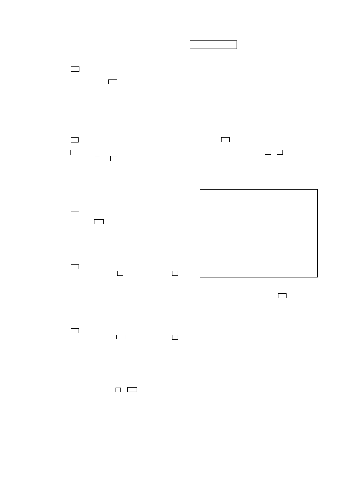
• SIGNAL PATH
: CD PLAY
: DVD PLAY
: SACD PLAY
: VIDEO
: AUDIO
DETECTOR
1
63
3
4
5
6
9
10
11
12
14
15
16
13
18
17
62
61
53
52
54
55
59
60
DVDRFP
RFSIN
A2
B2
C2
D2
CD E
CD F
A
B
C
D
B
A
D
C
B
A
D
C
CD A
CD B
CD C
CD D
CDLD
CDPD
DVDLD
DVDPD
ATOP
ATON
FNP
FNN
AIP
AIN
DIP
DIN
57
27
40
39
47
46
48
IC001
CD/DVD/SACD RF AMP,
FOCUS/TRACKING ERROR AMP
OPTICAL PICK-UP
BLOCK
(DBU-1)
2AXIS
DEVICE
FOCUS/
TRACKING
COIL
22
24
21
23
36 48
37 1
Q001
AUTOMATIC POWER
CONTROL (FOR DVD)
Q002
AUTOMATIC POWER
CONTROL (FOR CD)
LASER
DIODE
(FOR CD)
LASER
DIODE
(FOR DVD)
FOCUS COIL
DRIVE
34 3
35 4
TRACKING COIL
DRIVE
32
31
33
34
20
22
19
8
40
41
39
43
31
32
29
30
SLED MOTOR
DRIVE
IC501
FOCUS/TRACKING COIL DRIVER,
SPINDLE/SLED MOTOR DRIVER
27
28
SPINDLE MOTOR
DRIVE
MM
M1
(SPINDLE)
19
47
46
45
FFDR
FRDR
TFDR
TRDR
SFDR
SRDR
SLED_A
SLED_B
SLED
26
SE
TE
FE
RFDC
IC509
CD DECODER,
DIGITAL SERVO PROCESSOR
MIRR
FF
FR
FOK
COUT
SCLK
RF
A
B
C
D
F
E
CD LD
PD
DVD LD
FCS+
FCS–
TRK+
TRK–
SW
INLIM
D
C
B
A
RFAC
MIRR
DATA_RF
CLK_RF
SDEN
TE
FE
PI
TE
FE
PI
FE
TE
SDATA
SCLK
SDEN
LDON
36
VI25
FCS_JMP_2
FCS_JMP_1
50
RFAC
30
29
SLED MOTOR
DRIVE
MM
M2
(SLED)
38PI
BUFFER
MUTE12
20
MUTE34
21
MUTE5
22
TSD-M
13
7
10
43
FG
62
MUTE_2D
60
SP_ON
63
TSD-M
73
39
POWER SAVE
DSAVE
97
IC901 (1/2)
MECHANISM
CONTROLLER
61
7
LDON
28
INLIM
LDSEL
76 31
SDEN
2
FE
67
PI
66
COUT_CD
30
SDA
5
SCL
6
WP
7
15
SCOR
66
PCMD
67
BCK
65
LRCK
14
C2PO
17
WDCK
10
WFCK
80
EXCK
79
SBSO
BCLK
LRCK
C2PO
GSCOR
WFCK
EXCK
27M
768FS
SBSO
25
MDP
SCOR
SCOR
26
24
LOCK
LOCK_CD
75
13
GFS
GFS_CD
71
3
MUTE
MUTE_CD
59
7
SENS
SENS_CD
9
76
SQSO
SQSO
52
SCLK_CD
72
4
DATA
DATA_CD
49
63
MD2
71
XTAI
DOCTR/
ISBTEST
3
77
SQCK
69
XTSL
CDSP2
10
85
XRD
XRD
17
58
GFS_DVD
GFS
107
45
109
SCK_DSD
4
XRST_2753
AEP0
64
JIT
77
SACD/DVD
84
XWR
XWR
18
12
XCS_DVD
XCS
19
25
XRST_1882
XRST
164
22
INT0_DVD
XINT0
20
23
INT1_DVD
XINT1
21
SQCK
54
2
XRST
XDRST
98
6
CLOK
CLOK_CD
50
5
XLAT
LAT_CD
27
FOK_CD
74
MIRR
29
TE
65
SDCLK_RF
82
SDATA_RF
83
44
38
42
VC
CE
26
SSTP
AVC
MIRR
MIRR
DATA_RF
CLK_RF
SDEN
TE
FE
PI
21
DFCT
DFCT
48
XHWR
49
XHRD
93
MNT2
26
SDEF
46
HDRQ
53
XHAC
92
MNT1
17
WE
76
XMWR
33
OE
94
XMOE
18
RAS
78
XRAS
34
UCAS
95
XCAS
117
RFIN
135
SPO
137
MDIN2
170
XTL1
169
XTL2
167
XTAL
IC701
DVD DECODER
IC706
16Mbit
D-RAM
160
MDAT
158
BCLK
163
LRCK
155
C2PO
146
GSCOR
HDB0 – HDB7
MDB0 – MDB9,
MDBA – MDBF
I/O0 – I/O15A0 – A9
151
WFCK
147
EXCK
148
SBIN
BCLK
LRCK
C2PO
GSCOR
WFCK
EXCK
SCOR
SBSO
145
DFCT
DFCT
150
SCOR
IC703 (1/2)
BUFFER
IC703 (2/2)
COMPARATOR
IC906
CLOCK
GENERATOR
66-69, 71, 73-75, 96, 97,
99, 101, 102, 104-106
2-5, 7-10,
41-44, 46-49
44, 41, 39, 35,
32, 30, 27, 24
21-24,
27-32
MA0 – MA9
79, 80, 82-87,
89, 91
35
LCAS
TF
8
TR
FF
FR
FF
FR
TF
TR
7 8
XTI
XTO
D0 – D7
D0 – D7
9 10
SO1
SO2
13 3
SO3
MO1
X902
27MHz
14-21
172-176, 1, 2, 4
A0 – A7
A0 – A7
89-96
5, 7, 9-14
RF_AC
A
SD0 – SD7
B
XSRQ
H
XSRQ-ZIVA
I
J
WPK
D
768FS
F
27M
E
SDEF, XDCK,
XSAK, XSHD
SDEF
XSAK
XDCK
XSHD
C
5
SDA_EEP
99
SCL_EEP
100
WP_EEP
47
SDIN_DSD
46
SDOUT_DSD
24
MSCK_SAMBA
51
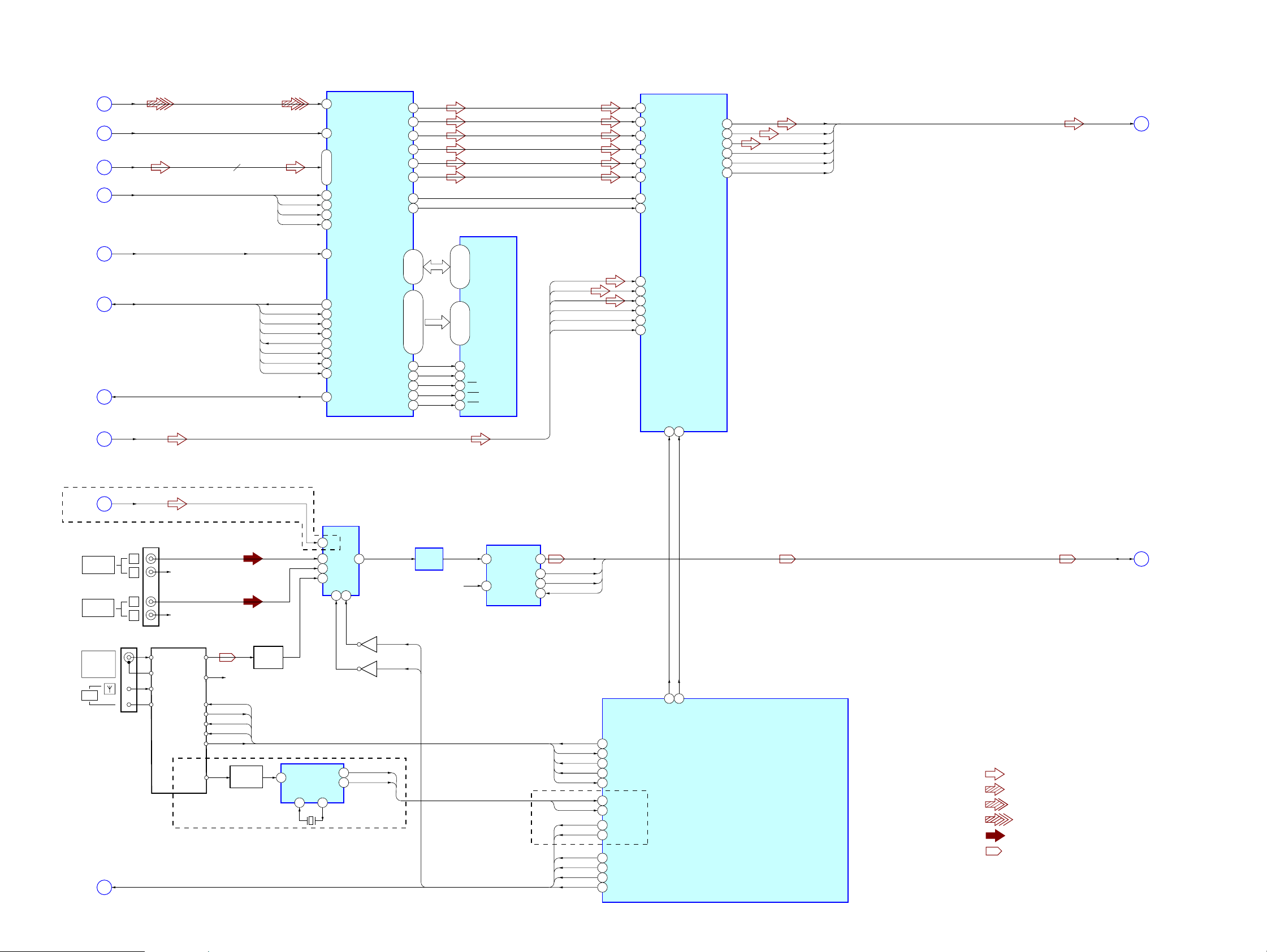
XMSLAT
48
READY_DSD
53
MUTE_DSD
MSDATO
ISBTEST
MSDATO, MSDATI, MSCK,
XMSLAT, SHRRDY, SHRMUT,
ISBTEST, XRST_DSD
MSDATI
MSCK
XMSLAT
SHRRDY
SHRMUT
6
MNT1
IC257
SACD/DVD
SELECT
IC903
EEPROM
XRST_DSD
IC503
AMP
8
VC
VC
20
MEVO
32
MIN
31
IC003
COMPARATOR
Q901
6-1. BLOCK DIAGRAM – RF SERVO Section –
(Page 26)
(Page 25)
(Page 25)
(Page 26)
(Page 26)
(Page 25)
(Page 25)
(Page 26)
(Page 26)
HCD-SB300
2525
HCD-SB300
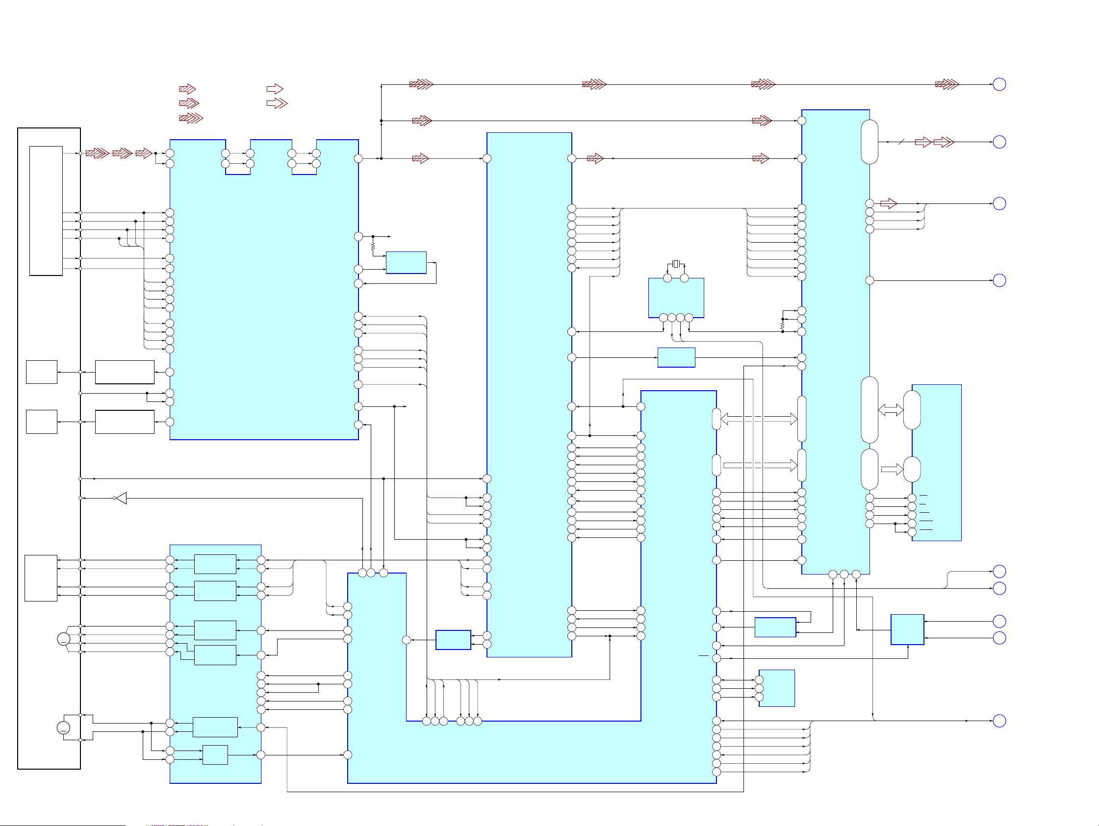
6-2. BLOCK DIAGRAM – DVD DSP Section –
• SIGNAL PATH
: VIDEO
: Y
: CHROMA
: COMPONENT VIDEO
: R, G, B
: AUDIO
: TUNER
IC207
DVD SYSTEM PROCESSOR
125
VDAC_2
131
VDAC_0
Q207, 208
BLANKOUT
SWITCH
183
SDCLK
179
SDEN
182
SDERROR
192
INT/EXT
151
DATA1(FLR)
154
DATA2(SLR)
155
DATA3(CSW)
147
XCK
148
LRCK
149
BCK
SDEF#
XSHD#
XDCK#
XSAK#
178
SDREQ
XSRQ_ZIVA
SDDATA0 – SDDATA7
177-174, 171-168
SD0
AV0 - AV7
AV0
AV1
AV2
AV3
AV4
AV5
AV6
AV7
SD1
SD2
SD3
SD4
SD5
SD6
SD7
ADC_DATA
BCK
LRCK
XCK
BCK
LRCK
XCK
SDEF
XSAK#, SDEF#,
XDCK#, XSHD#
XDCK
XSAK
XSHD
D3V
B
C
I
139
XIN
27M
F
202
RESET
110
MREQ
SYS RESET, MUTE REQ
SYS RESET
S
I2CDATA, I2CCLK
R
I2CCLK
I2CDATA
119
VDAC_4
128
190
VDAC_1
122
VDAC_3
IC204
EEPROM
IC901 (2/2)
MECHANISM CONTROLLER
Q202
5
DI
6
DO
1 8
R/B
WC
3
CS
4
SK
IC201
VIDEO AMP, 75Ω DRIVER
J105
J201
12
CBIN
10
CYIN
4
CVBS IN
18
3
CBOUT
MUTE1
25
S1
14
CRIN
20
CYOUT
23
CVBS OUT
2
CIN
6
YIN
26
COUT
27
S-DC OUT
21
YOUT
16
CROUT
CBOUT
CYOUT
VOUT
CROUT
CBOUT
(AEP, UK, Russian)(EXCEPT AEP, UK, Russian)
CYOUT
VOUT
R-CH
CROUT
AV SEL3
AV SEL1
13
MUTE2
12
34
IC904
FLIP-FLOP
IC902
SWITCHING
Q204
WIDE SWITCH
CE
WE
OE
ALE
IC231 – 233
ADDRESS LATCH
IC205
PROGRAMMABLE ROM
57-60, 64-71, 75-78,
81-84, 88-95, 99-102
25-27,
60-66,24,21
2,4,5,7,8,10,11,13,74,76,77,79,80,82,83,85,31,
33,34,36,37,39,40,42,45,47,48,50,51,53,54,56
HA1 – HA3HAD0 – HAD15
ADDRESS BUS
DATA & ADDRESS BUS
DATA & ADDRESS BUS
22, 19-14, 11-3 2, 207, 206
HAD0 – HAD15 HA1 – HA3
HAD0 – HAD15 HA1 – HA2
HAD0 – HAD15
HA1 –
HA3
HA4 –HA22
12
CE
WE
14
OE
1
A0 – A20
195
HCS0
WEH.UDS
27
HREAD
25
DQ0 – DQ15
56
MCLK
CE
WE
OE
IC203
128Mbit SD-RAM
68
CLK
DQ0 – DQ31 A0 – A11
MA0 – MA11
MD0 – MD31
42-33, 45, 46
49
MCS0
20
CS
53
MWE
17
WE
51
MRAS
19
RAS
52
MCAS
18
CAS
62
MDQM0
16
DQM0
73
MDQM1
71
DQM1
86
MDQM2
28
DQM2
97
MDQM3
59
DQM3
161
I2C_DA
78
I2C_SIO
160
I2C_CL
79
I2C_SCL
186
DRVTX
34
SO_ZIVA
187
DRVRX
33
SI_ZIVA
185
DRVCLK
35
SCK_ZIVA
184
HIRQ1
188
DRVRDY
36
DRVIRQ
37
DRVRDY
32
CS_ZIVA
191
RST_SPC
38
RST
116
HIRQ2
165
WRITE_CTRL(ZIVA_E2P)
162
CS_(ZIVA_E2P)
48
BA0
22
BS0
47
BA1
23
BS1
107
VS
XTAL
EXTAL
41 40
X901
20MHz
COMPONENT
VIDEO OUT
S VIDEO
(DVD ONLY)
MONITOR OUT
VIDEO
Y
PB/CB
PR/CR
AV SEL1, AV SEL3,
RGB SEL, DVD SEL
M
T
11
15
7
19
8
16
6
2
J202
R/C OUT
G OUT
B OUT
V/Y OUT
BLANK
OUT
FUNCTION
SW
A (L) IN
A (R) IN
EURO AV
T OUTPUT
(TO TV)
MUTE REQ
IC111
LEVEL
SHIFT
N
L
K
BCK-ZIVA
DATA1
DATA1 – DATA3,
LRCK-ZIVA,
BCK-ZIVA, XCK1
DATA2
DATA3
LRCK-ZIVA
XCK1
BCK
LRCK
XCK
O
IC256
LATCH
IC258
LATCH
IC259
LATCH
Q201
RGB
SEL
DVD
SEL
Q205, 206
FUNCTION
SWITCH
A (L) IN
8
8
69
CKE
• R-ch is omitted due to same as L-ch.
+
11 – 2, 34 – 4315 – 22, 24 – 31
Q210
(Page 24)
(Page 24)
(Page 26)
(Page 24)
(Page 24)
(Page 27)
(Page 27)
(Page 26)
(Page 26)
(Page 26)
(Page 26)
(Page 26)
HCD-SB300
2626
HCD-SB300
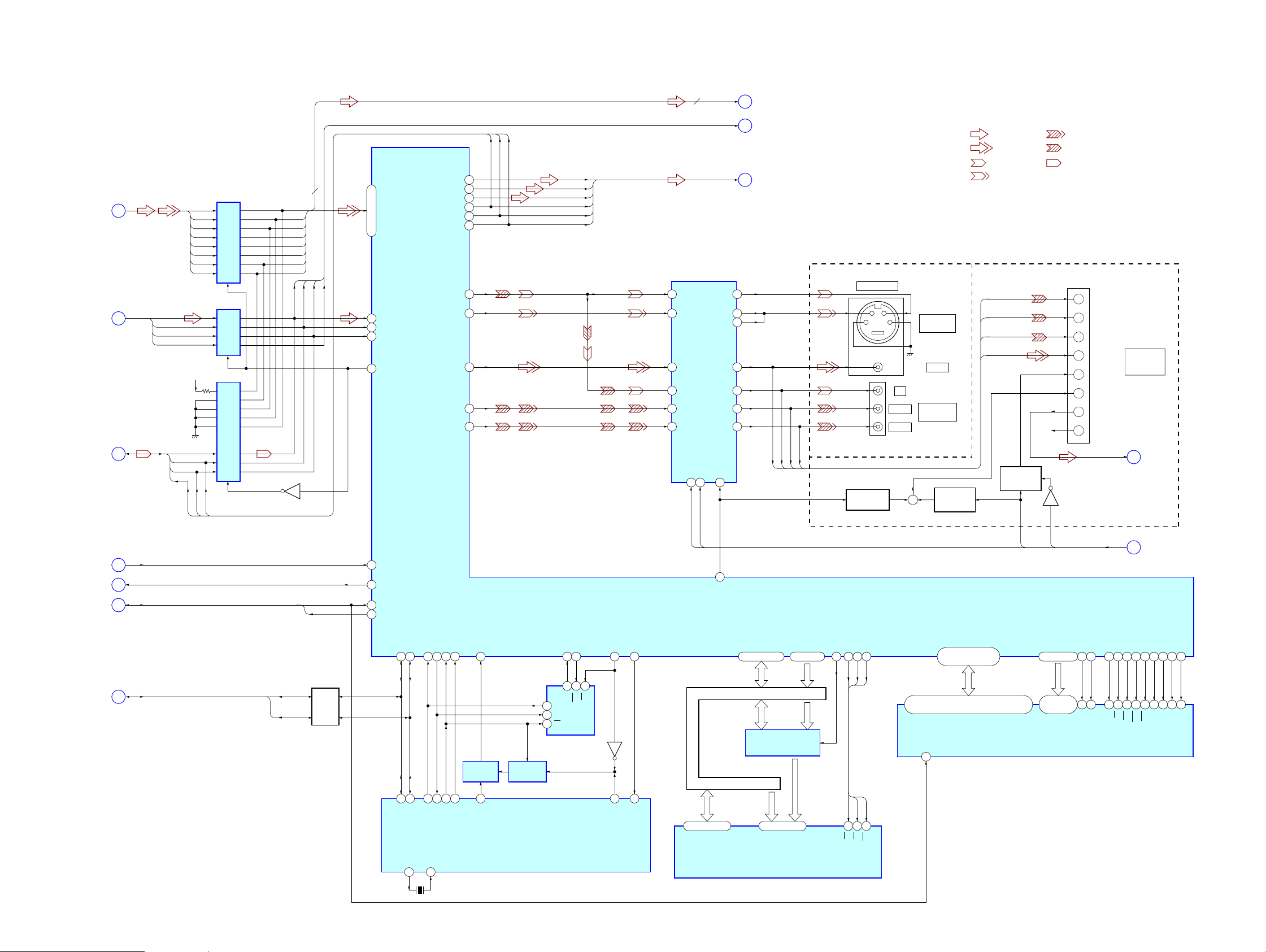
6-3. BLOCK DIAGRAM – AUDIO Section –
• SIGNAL PATH
: CD PLAY
: AUDIO
: DVD PLAY
: AUX IN
: TUNER
: SACD PLAY
RF_AC
WPK
M
AV SEL1, AV SEL3,
RGB SEL, DVD SEL
T
168
SDEF
165
XSHD
166
SDCK
167
XSAK
6
MSDATO
4
MSDATI
3
MSCK
2
XMSLAT
7
MSREADY
10
SMUTE
MSDATO
MSDATI
MSCK
XMSLAT
SHRRDY
SHRMUT
SDEF#
SDEF#, XSHD#,
XDCK#, XSAK#
XSHD#
XDCK#
XSAK#
64
DSAL
39
DSIFL
ADC_DATA
BCK
LRCK
35
EXIFLR
34
EXICSW
33
EXISLR
32
EXILRCK
31
EXIBCK
29
EXIMCK
ADC_DATA,
BCK, LRCK, XCK
9
XRST
123
WCK
126
WARFI
85
PLL-DI
82
PLL-CLK
84
PLL-CE
81
TUNED
83
PLL-DO
IC801
DSD DECODER
IC808
16Mbit
SD-RAM
IC802
DIGITAL AUDIO
PROCESSOR
IC509 (1/3)
SYSTEM CONTROLLER
Q203
J200
Q202
SD0 – SD7
169 – 176
143
XWE
15
WE
145
XRAS
17
RAS
144
XCAS
16
CAS
142
DCKE
34
CKE
35
CLK
DQ0 – DQ7
DQ0 – DQ7A0 – A11
2, 3, 5, 6, 8,
9, 11, 12
21-24, 27-32,
20, 19
139-136,
134-131
162-159, 157-154,
152, 151, 149, 148
A0 – A11
141
DCLK
66
DSAR
40
DSIFR
69
DSAC
41
DSICT
71
DSALFE
42
DSISW
74
DSALS
43
DSISL
76
DSARS
44
DSISR
60
BCKAO
38
DSBCK
13
EXCKO1
27
MCK
4
SELEXT
31
DF_SEL
20
PLRCK
19
PBCK
17
MCKOUT
23
POFLR
22
POCSW
21
POSLR
LRCKO
D1 - D3, SCK,
BCKO, LRCKO
BCKO
SCK
D1
D3
D2
IC203
AMP
FM/AM TUNER PACK
IC202
AUDIO INPUT
SELECTOR
IC352
A/D CONVERTER
Q212
AMP
4
Y3
2
Y2
1
Y0
3
10 9
Y
AB
15
DOUT
14
BCK
13
LRCK
5
Y1
1
V LIN
5
V RIN
R-CH
DO
CK
CE
TUNED
FM-DET
FM ANT
GND
AM ANT
GND
L-CH
R-CH
DI
PLL DO
PLL CK
PLL CE
TUNED
PLL DI
RDSC
RDSD
R-CH
R-CH
R-CH
A (L) IN
PLL DO
PLL CK
PLL CE
TUNED
PLL DI
COAXIAL
FM
75Ω
AM
SAT
AUDIO IN
VIDEO
AUDIO IN
AV0 – AV7
K
L
164
115
XSRQ
XSRQ
H
11
MCKI
768FS
E
J
D
A
TESTI
ISBTEST
XRST_DSD
DATA1
DATA3
DATA2
LRCK-ZIVA
BCK-ZIVA
XCK1
XCK
16
SYSCLK
87
AVS1
88
AVS2
86
AVS0
60
RDS_CLK
61
RDS_DATA
RDSC
RDSD
AV SEL2
AV SEL0
89
AVS3
AV SEL1
AV SEL2
AV SEL0
AV SEL3
91
RGB_SEL
90
DVD_SEL
RGB SEL
DVD SEL
41
DF_INT
47
INIT
L
R
L
R
MSDATO, MSDATI, MSCK,
XMSLAT, SHRRDY, SHRMUT,
ISBTEST, XRST_DSD
4
13 14
2
Q209
DET AMP
16
X201
4.332MHz
IC200
RDS DECODER
(AEP, UK, Russian)
(AEP, UK, Russian)
(AEP, UK, Russian)
MUX
XI XO
RDATA
RCLK
N
P
O
8
DATA1 – DATA3,
LRCK-ZIVA,
BCK-ZIVA, XCK1
• R-ch is omitted due to same as L-ch.
(Page 27)
(Page 25)
(Page 24)
(Page 24)
(Page 25)
(Page 25)
(Page 24)
(Page 24)
(Page 24)
(Page 25)
(Page 25)
(Page 25)

HCD-SB300
2727
HCD-SB300
6-4. BLOCK DIAGRAM – AMP, PANEL Section –
• SIGNAL PATH
: AUDIO
/RST
/SD
HP-MUTE
HP-SW
4 13
IC101
POWER DRIVER
IC102
POWER DRIVER
IC103, 104
POWER DRIVER
(SAME AS IC101, 102)
IC105, 106,107
POWER DRIVER
(SAME AS IC101, 102)
17
PWM_AP
2
PWM_BP
17
PWM_AP
2
PWM_BP
J800
TB301
(+)
(–)
OUT_A
OUT_B
IC108
STREAM PROCESSOR
IC301
HEADPHONE
AMP
31
DATA
36
XFSIIN
30
BCK
23
SCLATCH
27
INIT
19
SOFTMUTE
24
OVF FLAGR
25
OVF FLAGL
18
NSPMUTE
21
SCDT
29
LRCK
22
SCSHIFT
LATCH1
INIT
SOFTMUTE
SCDT
SHIFT
6
OUTR1
9
OUTL2
4
OUTR2
11
OUTL1
43
HPOUTL2
41
HPOUTR1
45
HPOUTL1
39
HPOUTR2
37
FSOCKO
38
FSOI
Q101, 102
OVER LOAD
DETECT
Q505
MUTING
CONTROL
/RST
/SD
4 13
FRONT
L
27
FL_D_DATA
29
FL_CLK
30
FL_STB
(+)
(–)
Q103, 104
OVER LOAD
DETECT
FRONT
R
(+)
(–)
IC109
STREAM PROCESSOR
IC509 (2/3)
SYSTEM CONTROLLER
IC803
FL DRIVER
31
DATA
36
XFSIIN
30
BCK
23
SCLATCH
27
INIT
21
SCDT
29
LRCK
22
SCSHIFT
11
OUTL1
4
OUTR2
9
OUTL2
1
HP SW
6
OUTR1
7
DIN
8
CLK
9
STB
Q105, 106
OVER LOAD
DETECT
(+)
(–)
Q107, 108
OVER LOAD
DETECT
(+)
(–)
IC110
STREAM PROCESSOR
31
DATA
36
XFSIIN
30
BCK
23
SCLATCH
27
INIT
SCDT
29
LRCK
22
21
SCSHIFT
6
OUTR1
9
OUTL2
4
OUTR2
11
OUTL1
48
XFSOIN
48
XFSOIN
14
XFSOOUT
Q109, 110
OVER LOAD
DETECT
REAR
L
(+)
(–)
Q111, 112
OVER LOAD
DETECT
9
DRIVE_RST
8
DRIVE_OCP
REAR
R
38
FSOI
20
PG MUTE
20
PG MUTE
20
PG MUTE
38
FSOI
CENTER
SPEAKER
TB302
SPEAKER
WOOFER
PHONES
D1
SCK
BCKO
LRCKO
LATCH2
INIT
INIT
SCDT
SHIFT
LATCH1
LATCH2
LATCH3
SCDT
SHIFT
D2
SCK
BCKO
LRCKO
LATCH3
INIT
SCDT
SHIFT
D3
SCK
BCKO
LRCKO
OVF1
19
SOFTMUTE
24
OVF FLAGR
25
OVF FLAGL
18
NSPMUTE
SOFTMUTE
OVF1
19
SOFTMUTE
24
OVF FLAGR
25
OVF FLAGL
18
NSPMUTE
SOFTMUTE
OVF2
OVF1
AMP 3.3V
FL801
FLUORESCENT
INDICATOR TUBE
Q800, 801,
Q803, 804,
MUTING
Q506, 507
SIRCS DETECT
Q814, 815
GRID DRIVE
Q301
PROTECT DETECT
IC305
OSC
D1 – D3, SCK,
BCKO, LRCKO
P
X450
49.152MHz
2
HP MUTE
HP-SW
HP-MUTE
43
DAMP SCDT
44
DAMP SHIFT
SG1 – SG16
45
DAMP LATCH1
46
DAMP LATCH2
47
DAMP LATCH3
48
DAMP INIT
SOFTMUTE
49
DAMP SOFT MUTE
OVF1
92
OVERFLOW1
OVF2
93
OVERFLOW2
14 – 29
GR3 – GR12
GR1,
GR2
40 – 31
Q812, 813, 816
LED DRIVE
20
KEY INT
I2CDATA,
I2CCLK
R
SYS RESET, MUTE REQ
S
34
SIRCS_IN
IC800
REMOTE CONTROL
RECEIVER
96 – 94
42, 41
KEY0 – KEY2
KEY0
S800 – 803,
S809, 811, 813,
S814, 816, 818
21
RM_INT
40
SYS RESET
38
I2C_CLK
37
I2C_DATA
I2CCLK
I2CDATA
39
MUTE REQ
SYS RESET
MUTE REQ
15
14
X501
5MHz
X2
X1
33
STBY_LED
32
BACKLIGHT
D802
STANDBY
D817, 820 – 824
(FL BACK LIGHT)
LPF
LPF
LPF
LPF
LPF
LPF
LPF
LPF
LPF
LPF
LPF
LPF
(+)
(–)
Q113, 114
OVER LOAD
DETECT
WOOFER
LPF
LPF
29, 30
25, 26
OUT_A
OUT_B
29, 30
25, 26
48
XFSOIN
14
XFSOOUT
(Page 26)
(Page 25)
(Page 25)
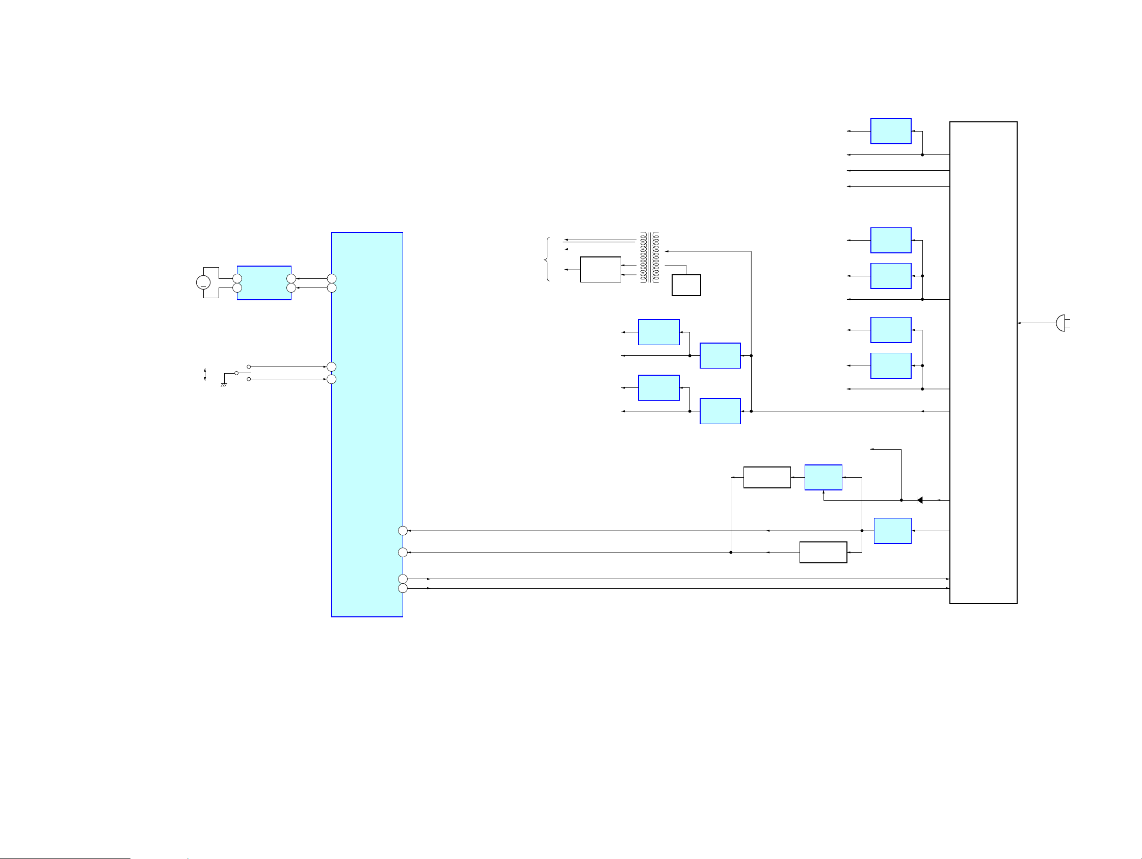
HCD-SB300
2828
HCD-SB300
6-5. BLOCK DIAGRAM – POWER SUPPLY Section –
(AC IN)
IC512
+5V
REGULATOR
IC502
+3.3V
REGULATOR
ZIVA A3V-1
Q508
RESET SWITCH
A5V, V5V
SWITCHING
REGULATOR
IC513
+5V
REGULATOR
IC907
+3.3V
REGULATOR
D810, 811,
D813, 814
RECT
ZIVA A3V-2
D5V
E3.3V
F1
F2
VFL
TO FLUORESCENT
INDICATOR TUBE
T801
DC/DC
CONVERTER
3.3V, D3.3V
IC211
+1.8V
REGULATOR
IC511
VOLTAGE
DETECT
IC803
+2.5V
REGULATOR
SACD 2.5V
ZIVA D1.8V
12V, M12V
IC515
+10V
REGULATOR
IC516
+7V
REGULATOR
MOTOR 7V
10V
Q509
RESET SWITCH
IC514
VOLTAGE
DETECT
Q806
OSC
6AC_ON/OFF
5V CONTROL
16RESET
23AC_CUT
IC509 (3/3)
SYSTEM CONTROLLER
LOD_POS
LOD_NEG
OUT1 FIN
OUT2 RIN
IC502
LOADING MOTOR DRIVE
M001
(LOADING)
M
7
9
4
2
79
80
OUT SW
IN SW
74
OUT
IN
76
S001
(DISC IN/OUT)
D502
E4V (MAIN)
6.2V (MAIN)
3.3V (MAIN)
12V (MAIN)
29.5V
29.5V (AMP)
AMP 12V, FAN 12V
12V (AMP)
IC303
+1.8V
REGULATOR
AMP 1.8V
AMP 3.3V
3.3V (AMP)
V_CONTROL
AC_ON/OFF
AC_DET
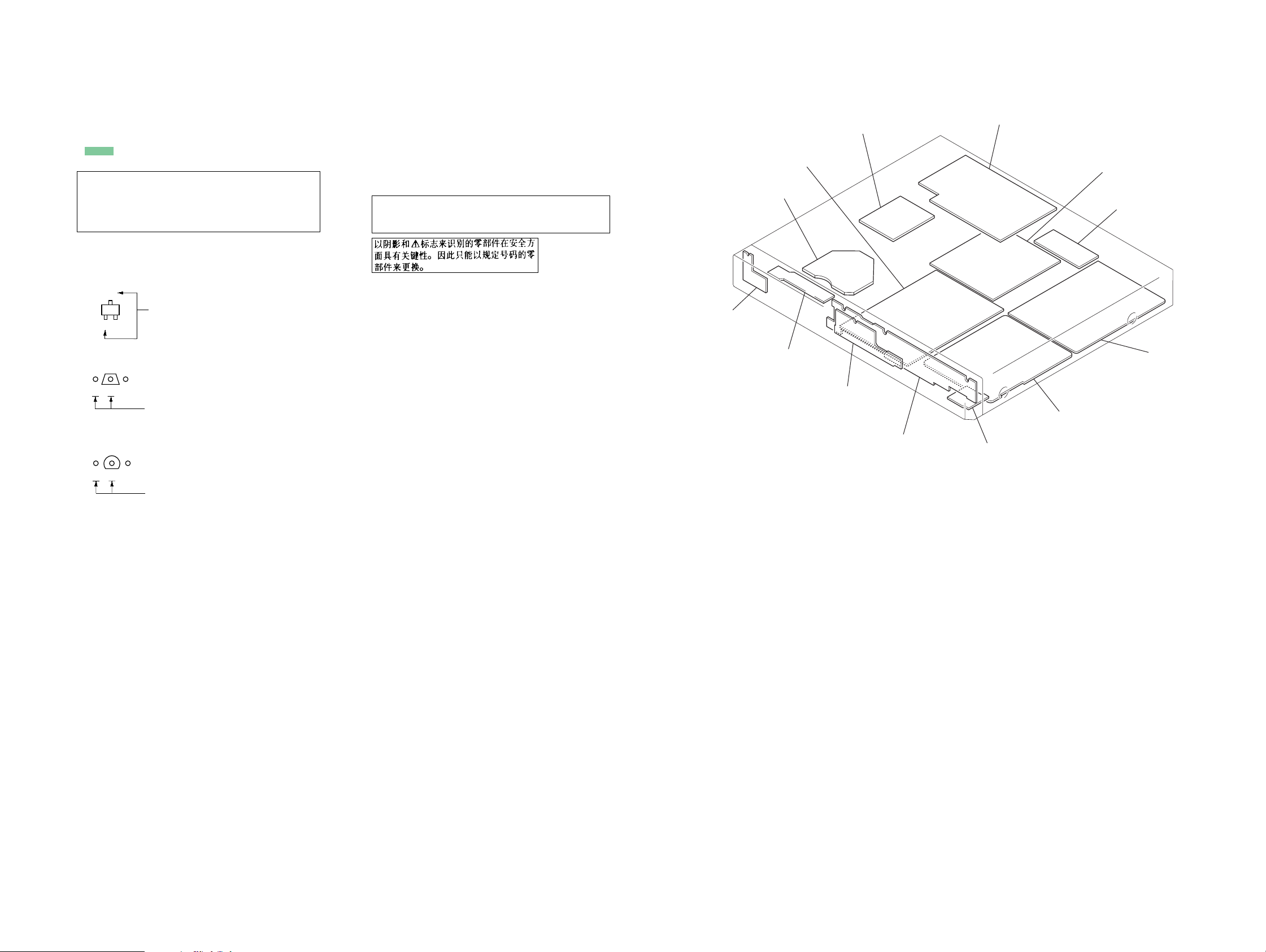
HCD-SB300
2929
HCD-SB300
• Note for Printed Wiring Boards and Schematic Diagrams
C
B
These are omitted.
E
Q
B
These are omitted.
CE
Q
Note on Schematic Diagram:
• All capacitors are in µF unless otherwise noted. (p: pF)
50 WV or less are not indicated except for electrolytics
and tantalums.
• All resistors are in Ω and
1
/
4
W or less unless otherwise
specified.
•
f : internal component.
• C : panel designation.
• A : B+ Line.
• B : B– Line.
• C : adjustment for repair.
• Voltages and waveforms are dc with respect to ground
under no-signal conditions.
no mark : DVD PLAY
(): SACD PLAY
∗ : Impossible to measure
• Voltages are tak en with a V OM (Input impedance 10 MΩ).
Voltage variations may be noted due to normal produc-
tion tolerances.
• Waveforms are taken with a oscilloscope.
Voltage variations may be noted due to normal produc-
tion tolerances.
• Circled numbers refer to waveforms.
• Signal path.
F : AUDIO
L : VIDEO
E : Y
a : CHROMA
q : R, G, B
r : COMPONENT VIDEO
d : TUNER
J : CD PLAY
c : DVD PLAY
I : SACD PLAY
f : AUX IN
• Abbreviation
AUS: Australian model
CH : Chinese model
EA : Saudi Arabia model
KR : Korean model
RU : Russian model
SP : Singapore model
• Circuit Boards Location
• Indication of transistor
Note on Printed Wiring Board:
• X : parts extracted from the component side.
• Y : parts extracted from the conductor side.
•
f
: internal component.
• : Pattern from the side which enables seeing.
(The other layers' patterns are not indicated.)
Caution:
Pattern face side: Parts on the pattern face side seen from
(Conductor Side) the pattern face are indicated.
Parts face side: Parts on the parts face side seen from
(Component Side) the parts face are indicated.
Note: The components identified by mark 0 or dotted line
with mark 0 are critical for safety.
Replace only with part number specified.
IO board
MAIN board
SPK board
AMP boar
d
SWITCHING REGULATOR
HP board
PANEL board
FL board
MS-128 board
POWER SW board
RF board
LF board
DMB07 board
B
These are omitted.
CE
Q
DMB07 and AMP boards are multi-layer printed board.
However, the patterns of intermediate layers have not been
included in diagrams.
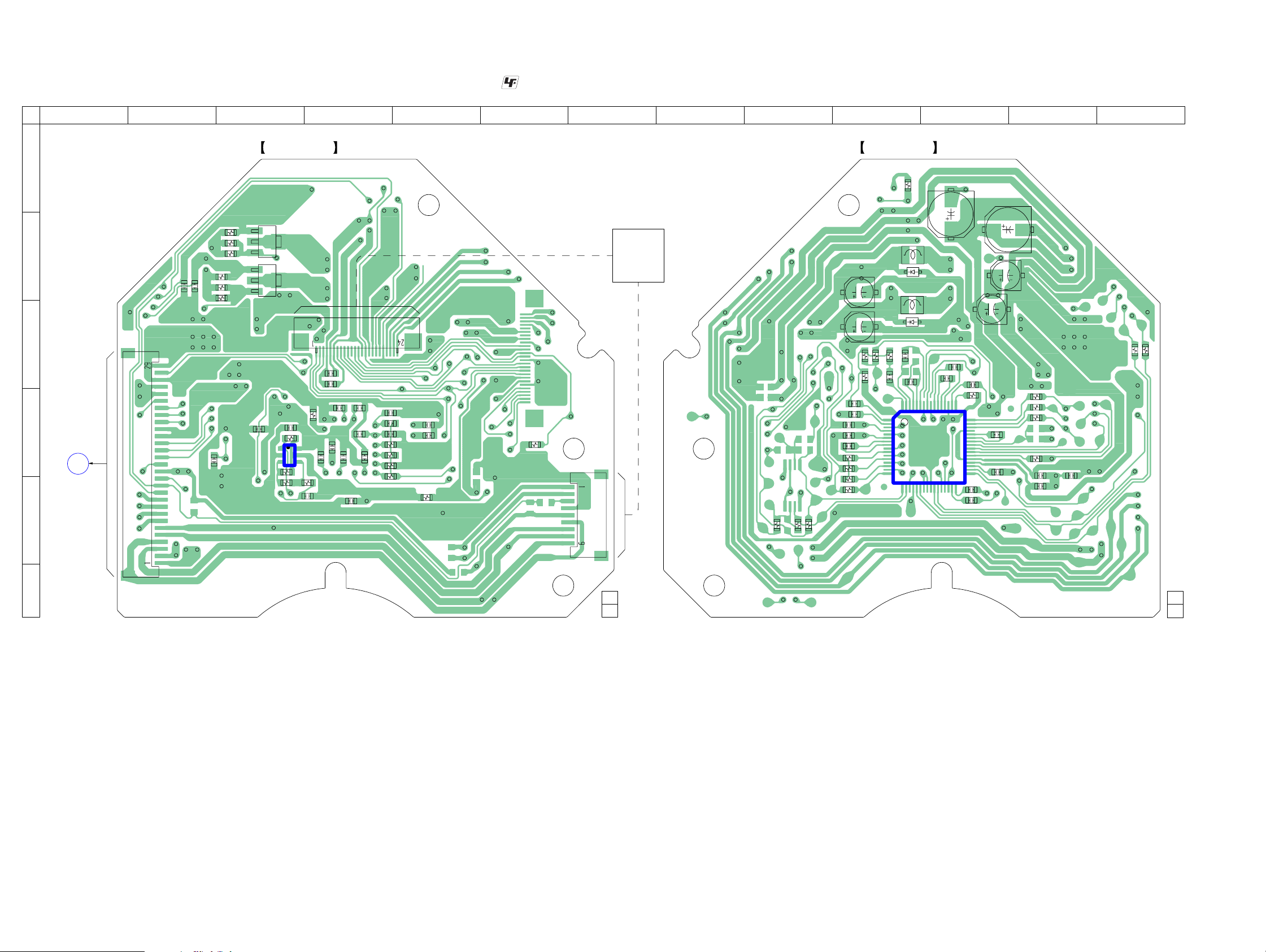
HCD-SB300
3030
HCD-SB300
6-6. PRINTED WIRING BOARD – RF Board –
• See page 29 for Circuit Boards Location.
:Uses unleaded solder.
C023
C028
C040
C037
R004
R005
C038
C022
C020
R016
R003
R018
R014
R012
C027
C041
C010
Q002
Q001
R007
C039
R001
C021
C013
R009
R008
C008
C017
C015
C011
C009
R021
CN003
CN001
CN002
C049
IC003
R033
R034
R047
R046
C050
C052
R091
R024
R025
R023
C029
C026
R026
C024
R027
R017
R015
C042
R013
R019
L002
L001
C003
D002
D001
R022
R020
C031
R011
C006
C005
C034
R006
R028
R029
C036
C032
C035
C033
C004
C012
C025
R010
C002
C030
C018
C016
C014
C019
R035
C001
R041
R031
C051
IC001
1
3
5
4
(COMPONENT SIDE)
RF BOARD
1-684-822-
12
(12)
1-684-822-
12
(12)
(CONDUCTOR SIDE)
RF BOARD
B
E
C
B
E
C
A
DMB07 BOARD
CN501
OPTICAL
TRAVERSE
UNIT
(DBU-1)
1 2 3 4 5 6 7 8 9 10 11 12 13
A
B
C
D
E
F
(Page 32)
Loading...