


 Loading...
HCD-WZ5
SERVICE MANUAL
Ver 1.1 2003. 11
•HCD-WZ5 is the tuner, and CD section in MHC-WZ5.
AEP Model
UK Model
E Model
Australian Model
|
Model Name Using Similar Mechanism |
NEW |
|
|
|
CD |
CD Mechanism Type |
CDM77B-K6BD47S |
|
|
|
Section |
Base Unit Name |
BU-K6BD47S |
|
|
|
|
Optical Pick-up Name |
KSM-213D |
|
|
|
SPECIFICATIONS
CD player section |
|
System |
Compact disc and digital |
|
audio system |
Laser |
Semiconductor laser |
|
(λ=780 nm) |
|
Emission duration: |
|
continuous |
Frequency response |
2 Hz – 20 kHz (±0.5 dB) |
Wavelength |
780 – 790 nm |
Signal-to-noise ratio |
More than 90 dB |
Dynamic range |
More than 90 dB |
OPTICAL CD DIGITAL OUT (European and |
|
Australian models only) |
|
(Square optical connector jack, rear panel) |
|
Wavelength |
660 nm |
Tuner section
FM stereo, FM/AM superheterodyne tuner
FM tuner section |
|
|
Tuning range |
87.5 |
– 108.0 MHz |
antenna |
FM lead antenna |
|
antenna terminals |
75 ohms unbalanced |
|
Intermediate frequency |
10.7 |
MHz |
AM tuner section |
|
Tuning range |
|
European model: |
531 – 1,602 kHz |
|
(with the tuning interval |
|
set at 9 kHz) |
Latin American model: |
530 – 1,710 kHz |
|
(with the tuning interval |
|
set at 10 kHz) |
|
531 – 1,710 kHz |
|
(with the tuning interval |
|
set at 9 kHz) |
Other model: |
530 – 1,710 kHz |
|
(with the tuning interval |
|
set at 10 kHz) |
|
531 – 1,602 kHz |
|
(with the tuning interval |
|
set at 9 kHz) |
antenna |
AM loop antenna |
antenna terminals |
External antenna terminal |
Intermediate frequency |
450 kHz |
General
Power requirements
Power voltage is D 9V and fed with STEREO CASSETTE DECK AMPLIFIER (DXA-WZ5) from the external SYSTEM CONTROL connectors. Power consumption
European model: 150 watts
0.3 watts (at the Power Saving Mode)
Except for European model:
180 watts
Dimensions (w/h/d) |
|
CD player/Tuner: |
Approx. 255 × 135 × |
Mass |
355 mm |
CD player/Tuner: |
Approx. 2.8 kg |
Design and specifications are subject to change without notice.
COMPACT DISC TUNER
9-877-331-02 |
Sony Corporation |
2003K16-1 |
Home Audio Company |
© 2003.11 |
Published by Sony Engineering Corporation |

HCD-WZ5
Ver 1.1 2003.11
NOTES ON HANDLING THE OPTICAL PICK-UP BLOCK OR BASE UNIT
The laser diode in the optical pick-up block may suffer electrostatic break-down because of the potential difference generated by the charged electrostatic load, etc. on clothing and the human body.
During repair, pay attention to electrostatic break-down and also use the procedure in the printed matter which is included in the repair parts.
The flexible board is easily damaged and should be handled with care.
NOTES ON LASER DIODE EMISSION CHECK
The laser beam on this model is concentrated so as to be focused on the disc reflective surface by the objective lens in the optical pickup block. Therefore, when checking the laser diode emission, observe from more than 30 cm away from the objective lens.
Laser component in this product is capable of emitting radiation exceeding the limit for Class 1.
This appliance is classified as a CLASS 1 LASER product. This label is located on the rear exterior.
The following caution label is located inside the apparatus.
CAUTION
Use of controls or adjustments or performance of procedures other than those specified herein may result in hazardous radiation exposure.
Notes on chip component replacement
•Never reuse a disconnected chip component.
•Notice that the minus side of a tantalum capacitor may be damaged by heat.
Flexible Circuit Board Repairing
•Keep the temperature of soldering iron around 270˚C during repairing.
•Do not touch the soldering iron on the same conductor of the circuit board (within 3 times).
•Be careful not to apply force on the conductor when soldering or unsoldering.
TABLE OF CONTENTS
1.GENERAL ·········································································· 4
2.DISASSEMBLY
2-1. Case··············································································· 7
2-2. Front Panel Assy ··························································· 8 2-3. PANEL Board, CD-TC-SW Board, ENTER-SW
Board, BACK-LIGHT Board, LCD Board ··················· 8 2-4. Tuner (FM/AM), WOOFER Board ······························ 9 2-5. MAIN Board, REGULATOR Board, HP-AMP Board ··· 9 2-6. CD mechanism deck (CDM77B-K6BD47S)·············· 10 2-7. Tray (AU) ···································································· 10 2-8. MS-128 Board ···························································· 11 2-9. Base Unit (BU-K6BD47S) ········································· 11 2-10. CD Board, Optical Pick-Up Block (KSM-213D) ······· 12
3.ELECTRICAL ADJUSTMENTS ······························· 13
4.TEST MODE ···································································· 14
5.DIAGRAMS
5-1. Circuit Boards Location ·············································· 15 5-2. Block Diagrams - Main Section - ······························· 16 5-3. Printed Wiring Board - CD Board - ···························· 17
5-4. Schematic Diagram - CD Board - ······························· 18 5-5. Printed Wiring Board - MAIN Section- ······················ 19 5-6. Schematic Diagram - MAIN Section (1/2) - ··········· 20 - MAIN Section (2/2) - ··········· 21 5-7. Printed Wiring Board - PANEL Board - ····················· 22
5-8. Schematic Diagram - PANEL Board - ························ 23 5-9. Printed Wiring Board - LCD/SWITCH Section - ······· 24 5-10. Schematic Diagram - LCD/SWITCH Section - ·········· 25 5-11. Printed Wiring Board - REGULATOR Board - ·········· 26 5-12. Schematic Diagram - REGULATOR Board - ············ 27 5-13. IC Block Diagrams ····················································· 28 5-14. IC Pin Function Description ······································· 29
6.EXPLODED VIEWS
6-1. Front Panel Section ····················································· 31
6-2. Chassis Section ···························································· 32
6-3. CD Mechanism Deck Section ····································· 33 6-4. Optical Pick-up Section (KSM-213D) ························ 34
7.ELECTRICAL PARTS LIST ······································· 35
2

HCD-WZ5
[When bringing in the equipment for service]
In case of repairing, please bring the entire system set([HCD-WZ5, DXA-WZ5],except for the speaker) to the service station.
Unleaded solder
Boards requiring use of unleaded solder are printed with the leadfree mark (LF) indicating the solder contains no lead.
(Caution: Some printed circuit boards may not come printed with the lead free mark due to their particular size.)
 : LEAD FREE MARK
Unleaded solder has the following characteristics.
•Unleaded solder melts at a temperature about 40°C higher than ordinary solder.
Ordinary soldering irons can be used but the iron tip has to be applied to the solder joint for a slightly longer time.
Soldering irons using a temperature regulator should be set to about 350°C.
Caution: The printed pattern (copper foil) may peel away if the heated tip is applied for too long, so be careful!
•Strong viscosity
Unleaded solder is more viscous (sticky, less prone to flow) than ordinary solder so use caution not to let solder bridges occur such as on IC pins, etc.
•Usable with ordinary solder
It is best to use only unleaded solder but unleaded solder may also be added to ordinary solder.
MODEL IDENTIFICATION
— BACK PANEL —
PARTS No.
|
|
|
|
|
|
|
|
MODEL |
|
|
PARTS No. |
|
|
|
|
AEP, UK models |
|
|
4-244-440-0s |
|
|
|
|
E2, E3 models |
|
|
4-244-440-1s |
|
|
|
|
AUS model |
|
|
4-244-440-2s |
|
|
|
|
KR, TW models |
|
|
4-244-440-7s |
|
|
|
|
•Abbreviation
AUS : Australian model
E2 : 120V AC Area in E model
E3 : 240V AC Area in E model
KR |
: Korean model |
TW |
: Taiwan model |
SAFETY-RELATED COMPONENT WARNING!!
COMPONENTS IDENTIFIED BY MARK 0OR DOTTED LINE WITH
MARK 0 ON THE SCHEMATIC DIAGRAMS AND IN THE PARTS
LIST ARE CRITICAL TO SAFE OPERATION. REPLACE THESE
COMPONENTS WITH SONY PARTS WHOSE PART NUMBERS
APPEAR AS SHOWN IN THIS MANUAL OR IN SUPPLEMENTS
PUBLISHED BY SONY.
3

HCD-WZ5
SECTION 1
GENERAL
This section is extracted from instruction manual.
Main unit
ALPHABETICAL ORDER
A – L
CD 5 (9, 10, 17, 18) CD SYNC 9 (17) Control lever 7 (7, 20) DIMMER w; ( 24) Disc tray ws
DISPLAY ql (15, 23, 24) Display window wa
EQ EDIT qk (20, 29) GROOVE 7 (19) Headphone jack qs
M – Z
MD (VIDEO) 2 (26)
MOVIE MODE 7 (19) MUSIC MODE 7 (19, 20) PLAY MODE/DIRECTION qg
(9, 10, 16, 17, 18, 30)
PUSH ENTER 7 (8, 10, 12, 20, 21, 22)
Remote sensor qd
REPEAT/FM MODE qh (10, 14) SURROUND 7 (20)
TAPE A/B 3 (16, 17, 18) TUNER MEMORY qf (12) TUNER/BAND 6 (12, 13, 18) TUNING MODE qj (12, 13) VOLUME qa (21)
BUTTON DESCRIPTIONS
?/1 (power) 1 (7, 13, 21, 29) X (pause) 4 (9, 16)
nN (play) 4 (9, 16, 17)
x (stop) 4 (7, 9, 13, 16, 17, 29) +M> (fast forward/go
forward) 4 (8, 9, 12, 16, 21, 30)
.m– (rewind/go back) 4 (8, 9, 12, 16, 21)
Z (open/close) 8 (8) z START q; (17, 18)
CD player/Tuner
4

HCD-WZ5
Remote control
ALPHABETICAL ORDER |
|
|
|
BUTTON DESCRIPTIONS |
|
|
|
|
|
|
|
|
|
|
|
|
|
A – L |
|
|
M – Z |
|
?/1 (power) 4 (7, 13, 21) |
ALBUM +/– qf (9, 10) |
MD (VIDEO) ql (26) |
m/M (rewind/fast forward) |
|||
CD 9 (9, 10, 17, 18) |
MOVIE MODE qa (19) |
5 (9, 16, 30) |
|||
CLEAR 8 (11) |
MUSIC MODE qj (19, 20) |
./> (go back/go forward) |
|||
CLOCK/TIMER SELECT 2 |
PRESET –/+ 5 (12, 13) |
5 (8, 9, 16, 21) |
|||
(22, 23) |
PROGRAM EDIT w; (17) |
nN (play) 5 (9, 16, 17) |
|||
CLOCK/TIMER SET 3 (8, 21, |
SLEEP 1 (21) |
X (pause) 5 (9, 16) |
|||
22) |
|
SURROUND qd (20) |
x (stop) 5 (9, 13, 16, 17) |
||
DISPLAY 6 (15, 23, 24) |
TAPE A/B qk (16, 17, 18) |
|
|||
DIMMER 7 (24) |
|
||||
TUNER/BAND 0 (12, 13, 18) |
|
||||
EFFECT qh (19, 20) |
|
||||
TUNING –/+ 5 (12, 13) |
|
||||
ENTER wa (8, 10, 12, 20, 22) |
|
||||
VOL +/– qs (21) |
|
||||
GROOVE qg (19) |
|
||||
|
|
|
|
||
1 2 3 4
|
5 |
|
|
|
wa |
6 |
|
|
|
7 |
|
|
||
|
|
|
||
w; |
8 |
|
|
|
ql |
9 |
Setting the clock |
||
qk |
q; |
|||
qj |
qa |
Use buttons on the remote for the operation. |
||
qh |
qs |
|||
1 |
Press ?/1 to turn on the system. |
|||
|
|
|||
qg |
qd |
2 |
Press CLOCK/TIMER SET. |
|
|
|
3 |
Press .or > repeatedly to set the hour. |
|
|
qf |
4 |
Press ENTER. |
|
|
|
5 |
Press .or > repeatedly to set the minute. |
|
|
|
6 |
Press ENTER. |
|
The clock starts working.
To adjust the clock
1 Press CLOCK/TIMER SET.
2 Press .or > repeatedly to select “CLOCK SET?”, then press ENTER.
3 Do the same procedures as step 3 to 6 above.
5
HCD-WZ5
Getting Started
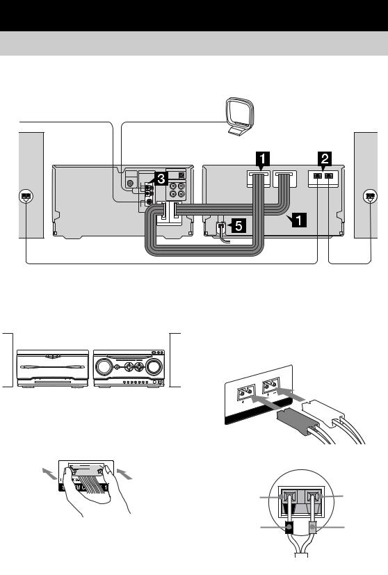
Hooking up the system
Perform the following procedures 1 to 5 to hook up your system using the supplied cords and accessories. Australian model is used for illustration purpose.
FM lead antenna |
AM loop antenna |
Amplifier/ |
|
CD player/ |
|
Tuner |
Tape deck |
Front
speaker (right)
Preparation
Place the components as shown below.
|
Amplifier/ |
|
CD player/ |
Tape deck |
Tuner |
Front speaker (left)
2Connect the speakers.
Connect the speaker cords to the SPEAKER terminals on the tape deck and to the terminals on the speakers as shown below.
L
R
1Connect the system control cables to the SYSTEM CONTROL connectors on the tape deck.
Connect to the same numbered jack in the order indicated on the rear panel.
SPEAKER 
Speakers
Black (#) |
Gray (3) |
Black (#) |
Gray (3) |
Note |
|
The system cable is used to send signals and electricity between the components for interlinked operation. Be sure to insert the connector horizontally until it clicks into place. Otherwise the system will not operate correctly.
6

SECTION 2 |
HCD-WZ5 |
Ver 1.1 2003.11 |
|
DISASSEMBLY |
|
• The equipment can be removed using the following procedure.
SET
|
|
CASE |
|
|
|
|
|
|
|
|
|
|
|
|
|
||
|
|
|
|
|
|
|
|
|
|
|
|
|
|
|
|
|
|
|
|
|
|
|
|
|
|
|
|
|
|
|
|
|
|
|
|
|
|
|
|
|
|
|
|
|
|
|
|
|
|
|
|
|
|
|
FRONT PANEL ASSY |
|
|
|
|
|
|
|
|
|
|
|
|
|
|||
|
|
|
|
|
|
|
|
|
|
|
|
|
|
|
|
|
|
|
|
|
|
|
|
|
|
|
|
|
|
||||||
|
|
|
|
|
|
|
|
|
|
|
|
|
|
|
|
|
|
|
|
|
|
|
|
|
|
|
|
|
|||||||
PANEL BOARD, CD-TC-SW BOARD, |
|
TUNER (FM/AM), |
|
CD MECHANISM DECK |
|
|
|||||||||||
ENTER-SW BOARD, |
|
WOOFER BOARD |
|
(CDM77B-K6BD47S) |
|
|
|||||||||||
BACK-LIGHT BOARD, LCD BOARD |
|
|
|
|
|
|
|
|
|
|
|
|
|||||
|
|
|
|
|
|
MAIN BOARD, |
|
|
|
|
|
|
|
|
|||
|
|
|
|
|
|
|
|
|
|
|
|
|
|
||||
|
|
|
|
|
|
|
|
|
|
|
|
|
|
||||
|
|
|
|
|
|
|
|
TRAY (AU) |
|
|
|
|
|||||
|
|
|
|
|
|
REGULATOR BOARD, |
|
|
|
|
|
|
|||||
|
|
|
|
|
|
|
|
|
|
|
|
|
|
||||
|
|
|
|
|
|
HP-AMP BOARD |
|
|
|
|
|
|
|
|
|||
|
|
|
|
|
|
|
|
|
|
|
|
|
|
|
|
|
|
|
|
|
|
|
|
|
|
|
|
|
|
BASE UNIT |
|
MS-128 BOARD |
|||
|
|
|
|
|
|
|
|
|
|
|
|
(BU-K6BD47S) |
|
|
|||
|
|
|
|
|
|
|
|
|
|
|
|
|
|||||
|
|
|
|
|
|
|
|
|
|
|
|
|
|
|
|
|
|
CD BOARD, OPTICAL PICK-UP BLOCK (KSM-213D)
Note : Follow the disassembly procedure in the numerical order given.
2-1. Case
4 case
3 two screws
1 three screws (case 3 TP2) ×
(+BVTP 3 8)
2 two screws (case 3 TP2)
7

HCD-WZ5
2-2. Front Panel Assy
How to eject the disk tray when the main power cannot be turned on.
3 loading panel
1
2
bottom side
6wire (NO601)
5 screw
(+BVTP 3 × 8) q; wire (flat type) (23 core) (CN109)
9connector (PN108)
8
7 claw
qa front panel section
4two screws (+BVTP 3 × 8)
2-3. PANEL Board, CD-TC-SW Board, ENTER-SW Board, BACK-LIGHT Board, LCD Board
|
qk Remove the soldering. |
qj two screws |
|
|
(+BVTP 2.6 × 8) |
|
ql LCD board |
|
w; LCD assy |
|
qf four screws |
|
|
|
|
|
(+BVTP 2.6 × 8) |
qg three claws |
|
4 eight screws |
|
|
(+BVTP 2.6 × 8) |
qh BACK-LIGHT board |
6 connector |
9 PANEL board |
(NO805B) |
||
|
|
8 wire (flat type) |
|
|
(23 core) (CN605) |
wa front panel assy |
|
|
5 two screws (+BVTP 2.6 × 8)
|
|
qa CD-TC-SW board |
3 button (cursor) |
q; two claws |
7 connector |
|
|
(CN603) |
|
|
qs two screws |
|
|
(+BVTP 2.6 × 8) |
2 nut |
|
|
1 knob (volume) |
|
qd ENTER-SW board |
8
HCD-WZ5
2-4. Tuner (FM/AM), WOOFER Board
|
3 wire (flat type) |
4 tuner (FM/AM) |
|
|
|
(11 core) |
|
||
|
|
9 back panel |
2 four screws |
|
5 wire (flat type) |
|
|
(+BVTP 3 × 8) |
|
|
|
|
||
(7 core) |
|
|
|
|
7 cord connector |
6 WOOFER board |
1 three screws |
||
(CN107) |
||||
|
|
|||
(+BVTP 3 × 8)
2-5. MAIN Board, REGULATOR Board, HP-AMP Board
6 MAIN board |
5 two claws |
1 screw (+BVTP 3 × 8)
2 wire (flat type) |
4 connector |
|
(5 core) (CN103) |
||
(CN114) |
||
|
3wire (flat type) (31 core) (CN101)
8cord connector (CN503,CN504)
7four screws (+BVTP 3 × 8)
8 REGULATOR board
9 screw (+BVTP 3 × 8)
q; HP-AMP board
9

HCD-WZ5
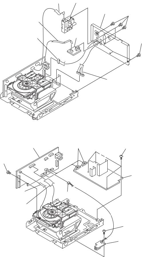
2-6. CD mechanism deck (CDM77B-K6BD47S)
4 CD mechanism deck |
|
(CDM77B-K6BD47S) |
3 three screws |
|
|
|
(+BVTP 3 × 8) |
2wire (flat type) (31 core) (CN101)
1 wire (flat type) (5 core) (CN103)
2-7. Tray (AU)
bottom side
2 two claws
1
3
4 tray (AU)
10
HCD-WZ5
2-8. MS-128 Board
1 belt
2wire (flat type) (5 core) (CN001)
4 MS-128 board
3 four claws
2-9. Base Unit (BU-K6BD47S)
6 belt
8 support
q; pulley gear
qa driving gear
4 chucking yoke
7 claw
qs chuck cam
1 two claws
5 pulley (AT) assy
9 claw
2
3 base unit (BU-K6BD47S)
11

HCD-WZ5
Ver 1.1 2003.11
2-10. CD Board, Optical Pick-Up Block (KSM-213D)
qd optical pick-up block (KSM-213D)
qs two insulators
qa two coil springs
q; two screws (+PTPWHM 2.6)
5 CD board
1 Remove four solders of motor.
qf holder (213)
9 two insulators
8 two coil springs
7 two screws (+PTPWHM 2.6)
6wire (flat type) (16 core)
4 gap tube
3screw
(+BVTP 2.6 × 8)
2wire (flat type) (31 core) (CN101)
12
HCD-WZ5
SECTION 3
ELECTRICAL ADJUSTMENTS
CD SECTION
Note:
1.CD Block is basically constructed to operate without adjustment.
2.UseYEDS-18 disc (3-702-101-01) unless otherwise indicated.
3.Use an oscilloscope with more than 10 MΩ impedance.
4.Clean the object lens by an applicator with neutral detergent when the signal level is low than specified value with the following checks.
5.Check the focus bias check when optical block is replaced.
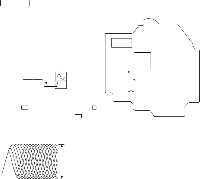
Focus Bias Check
|
oscilloscope |
|
(DC range) |
BD board |
|
TP5 (RF AC) |
+ |
TP7 (DVC) |
– |
Procedure :
1.Connect an oscilloscope to TP5 (RF AC) and TP7 (DVC) on the CD board.
2.Press the ?/1 button to turn the power on, and press the Z button to open the CD disc tray.
3.Put the test disc (YEDS-18) in and press the gG button to play-back.
4.Confirm that the oscilloscope waveform is as shown in the figure below. (eye pattern)
A good eye pattern means that the diamond shape (s) in the center of the waveform can be clearly distinguished.
VOLT/DIV: 200 mV
TIME/DIV: 500 ns
level:
1.2 ± 0.1 Vp-p
Checking Location:
– CD BOARD (Side B) –
IC150
IC101
TP7(DVC)
TP5(RF AC)
IC103
13

HCD-WZ5
SECTION 4
TEST MODE
[Cold Reset]
•The cold reset clears all data including preset data stored in the RAM to initial conditions. Execute this mode when returning the set to the customer.
Procedure:
1. Press three buttons x , EQ EDIT and ?/1 simultaneously.
2.The liquid crystal display does not display any message and the set is reset.
[MD/VIDEO Function Selection Mode]
• This mode is used to select the function of MD or VIDEO.
Procedure:
1. |
Press the |
?/1 |
button to turn the set on. |
|||
2. |
Press the |
MD(VIDEO) |
and |
?/1 |
buttons simultaneously. |
|
3.The function will change from MD to VIDEO, and "VIDEO" is displayed.
4.To change change back to MD , repeat the same procedure.
[AM Channel Step 9 kHz/10kHz Selection Mode]
•Either the 9 kHz step or 10 kHz step can be selected for the AM channel step.
Procedure:
1.Set the function to AM.
2.Turn off the main power.
3. |
While depressing the |
x |
button, press the |
?/1 |
button to turn |
|
on the main power. |
||||
4. |
The channel step is changed over. |
||||
* For E model only
[CD Ship Mode (without Cold Reset)]
•This mode moves the optical pick-up to the position durable to vibration. Use this mode when returning the set to the customer after repair.
Procedure:
1.Press the ?/1 button to turn the set on.
2.Set the function to CD.
3.Press the x button and the M (Control lever) button simultaneously.
4.After the "STANDBY" display blinks six times, the message "LOCK" is displayed on the liquid crystal display, and the CD ship mode is set.
[CD Ship Mode (without Cold Reset)]
• This mode is used to perform the CD Ship Mode with Cold Reset.
Procedure:
1.Press the ?/1 button to turn the set on.
2.Set the function to CD.
3.Press three buttons x , z START (REC PAUSE) and
.m – simultaneously.
4.After the "STANDBY" display blinks six times, the message "LOCK" is displayed on the liquid crystal display, and the CD ship mode is set.
[Disc Tray Lock]
•The disc tray lock function for the antitheft of an demonstration disc in the store is equipped.
Setting Procedure :
1.Press the ?/1 button to turn the set on.
2.Set the function to CD.
3. |
Press two buttons of x and Z simultaneously for five seconds. |
4. |
The message “LOCKED” is displayed and the tray is locked. |
Releasing Procedure :
1.Press two buttons of x and Z simultaneously for five seconds again.
2.The message “UNLOCKED” is displayed and the tray is unlocked.
Note :When “LOCKED” is displayed, the tray lock is not released by turning power on/off with the ?/1 button.
[GC Test Mode]
•This mode is used to check the software version, key board, VACS level, liquid crystal display and LEDs.
Procedure:
1. Press three buttons x , z START (REC PAUSE) and TUNER/BAND simultaneously.
2.Segments of the liquid crystal display and LEDs are all turned on.
3.To enter the software version display mode, press the .m– button. The model name and destination are displayed.
4.Each time the .m– button is pressed, the display changes in the following order. MC, GC, CD, CDD, CDMA, CDMB, BDA, BDB, ST, TA, TM, TC and MD. Each time the + M> button is pressed, the contents of the version display change.
5.Press the hH button, and the key check mode is activated.
6.In the key check mode, "K 0 V 0" is displayed. Each time a button is pressed, "K 0" value increases. However, once a button is pressed, it is no longer taken into account. "V 0" value increases like 1, 2, 3 ... if rotaing the VOLUME knob clockwise, or it decreases like 0, 9, 8 ... if rotating couterclockwise.
7.To exit from this mode, press three buttons in the same manner as step 1, or disconnect the power cord.
• VACS Level Display Mode
Procedure:
1. Press three buttons x , z START (REC PAUSE) and TUNER/BAND simultaneously.
2.Press the X button. The VACS level "VACS 0+0" is displayed.
3.To exit from this mode, press three buttons in the same manner
as step 1, or disconnect the power cord.
• Display Check
Procedure:
1.Press three buttons x , z START (REC PAUSE) and TUNER/BAND simultaneously.
2.Press the x button and the display changes. Each time the x button is pressed, the pattern of segments changes.
3.To exit from this mode, press three buttons in the same manner as step 1, or disconnect the power cord.
[VACS ON/OFF Mode]
• This mode is used to switch on and off the VACS (Variable Attenuation Control System).
Procedure:
1.Press the ?/1 button to turn the set on.
2.To enter the test mode, press three buttons x , z START (REC PAUSE) and MOVIE MODE simultaneously.
3.The message "VACS OFF" or "VACS ON" appears.
14
Loading...