


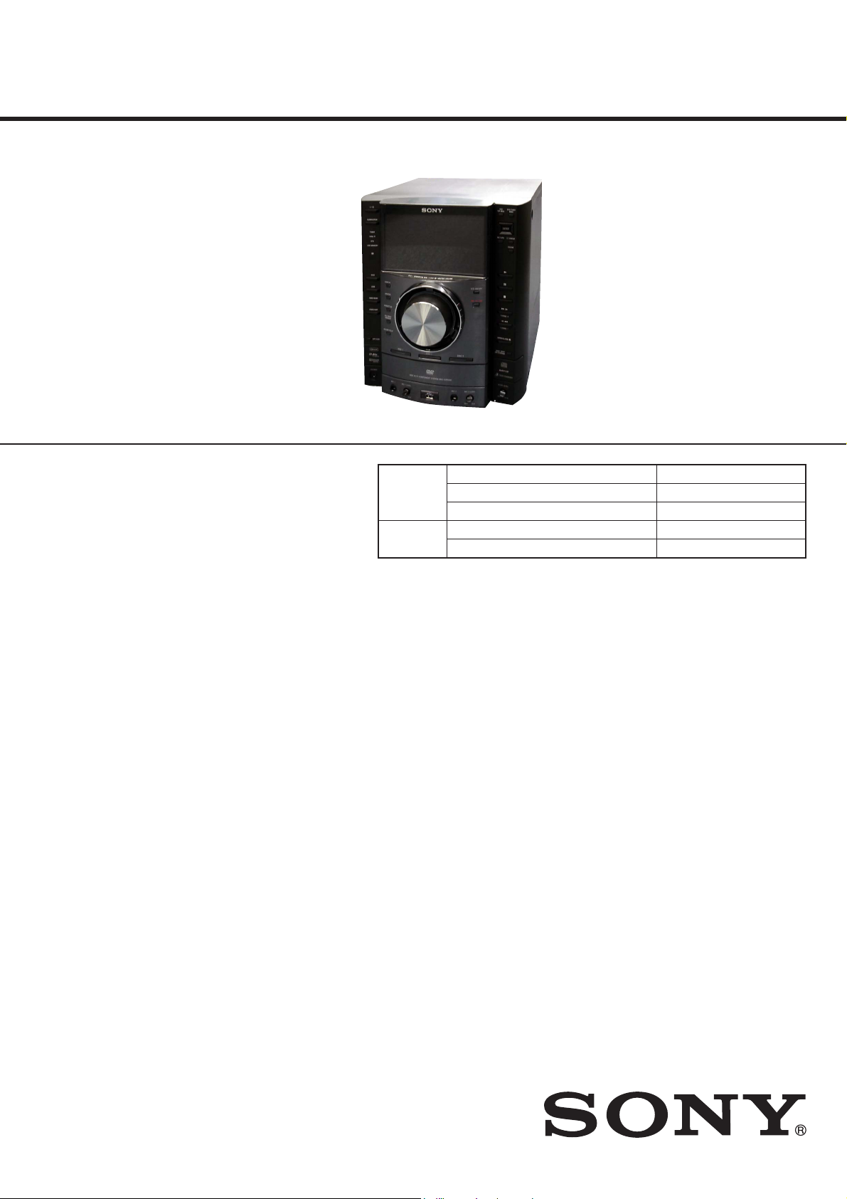
HCD-GZR88D
SERVICE MANUAL
Sony Corporation
Audio&Video Business Group
Published by Sony Techno Create Corporation
HCD-GZR88D/GZR99D
HCD-GZR99D: E2, E51, AR, MX Model
DVD DECK RECEIVER
HCD-GZR88D/GZR99D: E3, E4, E15, PH, SP Model
DVD RECEIVER
9-889-536-01
2009F04-1
©
2009.06
E Model
Ver. 1.0 2009.06
• HCD-GZR88D/GZR99D are the tuner,
deck, DVD and amplifi er section
in MHC-GZR88D/GZR99D.
DVD
Section
Model Name Using Similar Mechanism HCD-GZR77D
DVD Mechanism Type CDM74HF-DVBU101
Optical Pick-up Name KHM-313CAB
Tape Deck
Section
Model Name Using Similar Machanism HCD-GZR77D
Tape Transport Mechanism T ype CWP42FR605
SPECIFICATIONS
Amplifi er Section
The following measured at AC 127 V, 60 Hz (Mexican model)
The following measured at AC 120, 220, 240 V, 50/60 Hz (Other models)
MHC-GZR99D
Power output (rated): 135 W + 135 W
(at 6 Ω, 1 kHz, 1% THD, at LINK MODE)
RMS output power (reference)
Front speaker: 175 W + 175 W
(per channel at 8 Ω, 1 kHz, 10% THD)
Satellite speaker: 70 W + 70 W
(per channel at 24 Ω, 1 kHz, 10% THD)
Subwoofer: 210 W (at 6 Ω, 100 Hz, 10% THD)
MHC-GZR88D
Power output (rated): 125 W + 125 W
(at 6 Ω, 1 kHz, 1% THD, at LINK MODE)
RMS output power (reference)
Front speaker: 175 W + 175 W
(per channel at 8 Ω, 1 kHz, 10% THD)
Satellite speaker: 70 W + 70 W
(per channel at 24 Ω, 1 kHz, 10% THD)
– Continued on next page –
Photo: HCD-GZR99D: E2 model

HCD-GZR88D/GZR99D
2
SAFETY-RELATED COMPONET WARNING!
COMPONENTS IDENTIFIED BY MARK 0 OR DOTTED LINE
WITH MARK 0 ON THE SCHEMATIC DIAGRAMS AND IN
THE PARTS LIST ARE CRITICAL TO SAFE OPERATION.
REPLACE THESE COMPONENTS WITH SONY PARTS
WHOSE PART NUMBERS APPEAR AS SHOWN IN THIS
MANUAL OR IN SUPPLEMENTS PUBLISHED BY SONY.
Inputs
VIDEO/SAT VIDEO IN (phono jack):
1 Vp-p, 75 ohms
VIDEO/SAT AUDIO IN L/R (phono jacks):
voltage 250/450 mV, impedance 47 kilohms
MIC 1/MIC 2 (phone jacks):
sensitivity 1 mV, impedance 10 kilohms
Outputs
VIDEO OUT (phono jack):
max. output level 1 Vp-p, unbalanced,
Sync negative, load impedance 75 ohms
COMPONENT VIDEO OUT:
Y: 1 Vp-p, 75 ohms
PB/CB: 0.7 Vp-p, 75 ohms
PR/CR: 0.7 Vp-p, 75 ohms
DVD DIGITAL OUT (Square optical connector jack, rear panel):
Wavelength 650 nm
PHONES (stereo mini jack):
accepts headphones of 8 ohms or more
SUBWOOFER OUT (MHC-GZR88D only):
Voltage 1 V, impedance 1 kilohm
FRONT SPEAKER: Use only the supplied speaker SS-GZR99D.
SATELLITE SPEAKER: Use only the supplied speaker SS-RSX99D.
SUBWOOFER (MHC-GZR99D only):
Use only the supplied subwoofer
SS-WGV99D.
(USB) port: Type A (1)
Maximum current: 500 mA
Disc player section
System: Compact disc and digital audio and video
system
Laser Diode Properties
Emission duration:
Continuous Laser Output*:
Less than 44.6μW
*This output is the value measurement
at a distance of 200mm from the objective
lens surface on the Optical Pick-up Block
with 7mm aperture.
Frequency response
DVD (PCM 48 kHz): 2 Hz − 22 kHz (±1 dB)
CD: 2 Hz − 20 kHz (±0.5 dB)
Video color system format
Latin American model: NTSC
Other models: NTSC and PAL
Tape deck section (except for Latin American models)
Recording system: 4-track 2-channel, stereo
Tuner section
FM stereo, FM/AM superheterodyne tuner
FM tuner section
Tuning range: 87.5 − 108.0 MHz (50 kHz step)
Antenna: FM lead antenna
Antenna terminals: 75 Ω unbalanced
Intermediate frequency:
10.7 MHz
AM tuner section
Tuning range:
Latin American model:
530 – 1,710 kHz (with 10 kHz tuning interval)
531 – 1,710 kHz (with 9 kHz tuning interval)
Other models: 531 – 1,602 kHz (with 9 kHz tuning interval)
530 – 1,610 kHz (with 10 kHz tuning interval)
Antenna: AM loop antenna
Antenna terminals: External antenna terminal
Intermediate frequency:
450 kHz
General
Power requirements
Argentine and Thai models:
AC 220 V, 50/60 Hz
Mexican model: AC 127 V, 60 Hz,
Other models: AC 120, 220, 230 − 240 V, 50/60 Hz,
adjustable with voltage selector
Power consumption
MHC-GZR99D: 215 W
MHC-GZR88D: 170 W
Dimensions (w/h/d) (excl. speakers):
Approx. 280 × 326 × 440 mm
Mass (excl. speakers)
MHC-GZR99D: Approx. 13.2 kg (Latin American models),
approx.13.7 kg (other models)
MHC-GZR88D: Approx. 13.2 kg
Design and specifi cations are subject to change without notice.
HCD-GZR88D/GZR99D
3
UNLEADED SOLDER
Boards requiring use of unleaded solder are printed with the lead-
free mark (LF) indicating the solder contains no lead.
(Caution: Some printed circuit boards may not come printed with
the lead free mark due to their particular size)
: LEAD FREE MARK
Unleaded solder has the following characteristics.
• Unleaded solder melts at a temperature about 40 °C higher
than ordinary solder.
Ordinary soldering irons can be used but the iron tip has to be
applied to the solder joint for a slightly longer time.
Soldering irons using a temperature regulator should be set to
about 350 °C.
Caution: The printed pattern (copper foil) may peel away if
the heated tip is applied for too long, so be careful!
• Strong viscosity
Unleaded solder is more viscous (sticky, less prone to fl ow)
than ordinary solder so use caution not to let solder bridges
occur such as on IC pins, etc.
• Usable with ordinary solder
It is best to use only unleaded solder but unleaded solder may
also be added to ordinary solder.
NOTES ON CHIP COMPONENT REPLACEMENT
• Never reuse a disconnected chip component.
• Notice that the minus side of a tantalum capacitor may be dam-
aged by heat.
FLEXIBLE CIRCUIT BOARD REPAIRING
• Keep the temperature of soldering iron around 270 °C during
repairing.
• Do not touch the soldering iron on the same conductor of the
circuit board (within 3 times).
• Be careful not to apply force on the conductor when soldering
or unsoldering.
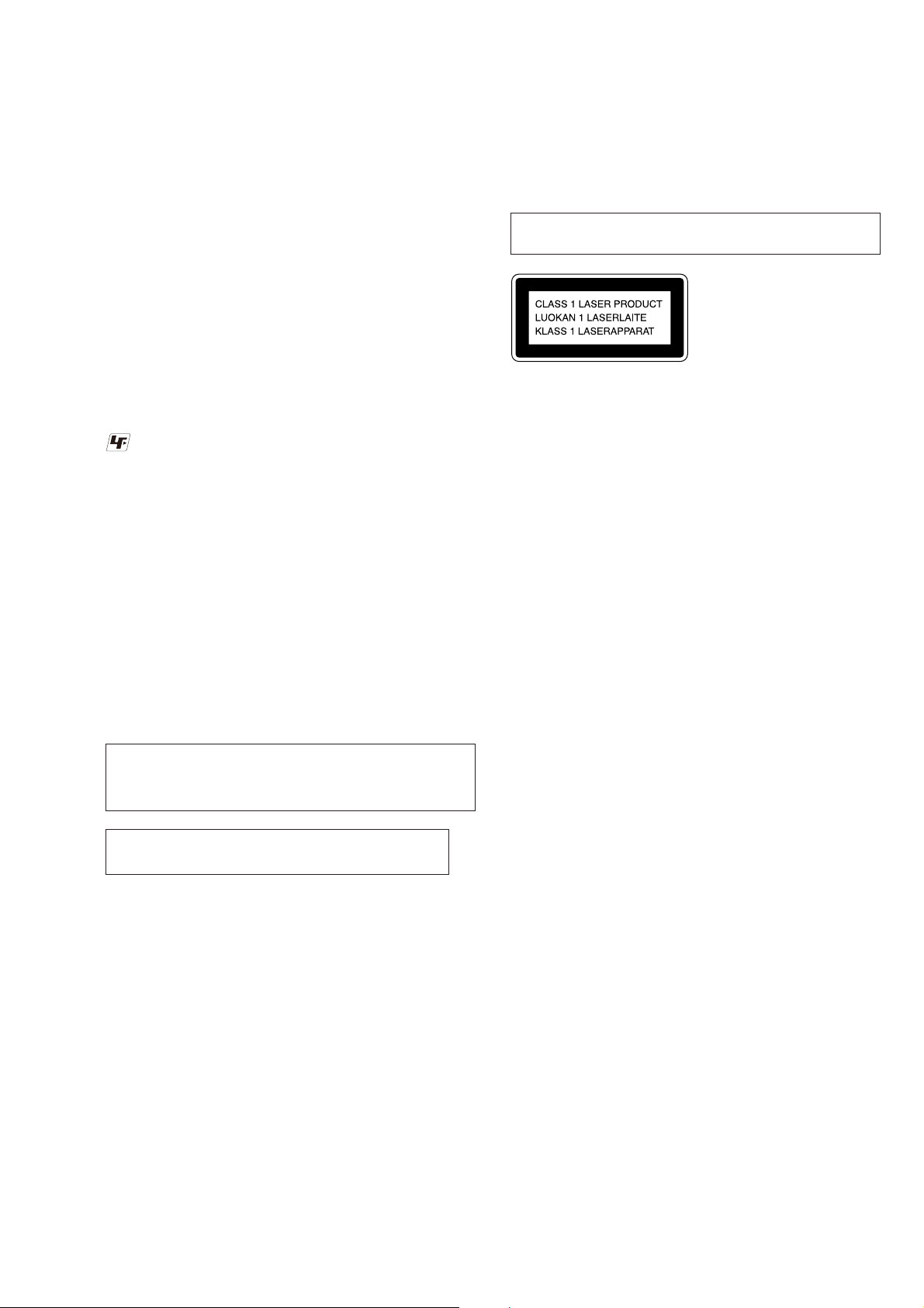
Laser component in this product is capable of emitting radiation
exceeding the limit for Class 1.
This appliance is classifi ed as
a CLASS 1 LASER product.
This marking is located on the
rear exterior.
CAUTION
Use of controls or adjustments or performance of procedures
other than those specifi ed herein may result in hazardous radia-
tion exposure.
NOTES ON HANDLING THE OPTICAL PICK-UP
BLOCK OR BASE UNIT
The laser diode in the optical pick-up block may suffer electrostat-
ic break-down because of the potential difference generated by the
charged electrostatic load, etc. on clothing and the human body.
During repair, pay attention to electrostatic break-down and also
use the procedure in the printed matter which is included in the
repair parts.
The fl exible board is easily damaged and should be handled with
care.
NOTES ON LASER DIODE EMISSION CHECK
The laser beam on this model is concentrated so as to be focused
on the disc refl ective surface by the objective lens in the optical
pickup block. Therefore, when checking the laser diode emission,
observe from more than 30 cm away from the objective lens.
HCD-GZR88D/GZR99D
4
Model Parts No.
GZR88D: E3, E15
4-133-526-0[]
GZR88D: E4
4-133-526-1[]
GZR88D: E12
4-133-526-2[]
GZR88D: SP
4-133-526-3[]
GZR88D: TH
4-133-526-4[]
GZR88D: PH
4-133-526-5[]
GZR99D: E3, E15
4-133-527-0[]
GZR99D: E4
4-133-527-1[]
GZR99D: SP
4-133-527-2[]
GZR99D: PH
4-133-527-3[]
GZR99D: E2, E51, MX
4-133-527-4[]
GZR99D: AR
4-133-527-6[]
MODEL IDENTIFICATION
– Back Panel –
• Abbreviation
E3 : 240V AC area in E model
E15 : Iran model
E4 : 110 – 120V/220 – 240V AC area in E model
E12 : 220 – 240V AC area in E model
SP : Singapore model
TH : Thai model
PH : Philippines model
E2 : 120V AC area in E model
E51 : Chilean and Peruvian model
MX : Mexican model
AR : Argentina model
Parts No.

HCD-GZR88D/GZR99D
5
1. SERVICING NOTES ............................................. 6
2. DISASSEMBLY
2-1. Case (Side-L), Case (Side-R) .......................................... 9
2-2. Top Panel Section ........................................................... 9
2-3. Loading Panel ................................................................. 10
2-4. Chassis ............................................................................ 10
2-5. Front Panel Section ......................................................... 11
2-6. Back Panel Section ......................................................... 11
2-7. MAIN Board ................................................................... 12
2-8. POWER AMP Board ...................................................... 12
2-9. DVD Mechanism Deck, Tuner (TM901) ........................ 13
2-10. MIC Board, USB-LED Board ........................................ 13
2-11. Panel (FL) Section .......................................................... 14
2-12. Liquid Crystal Display Panel (LCD101) ........................ 14
2-13. FRONT Board, VOLUME Board ................................... 15
2-14. TC-AMP Board
(Except HCD-GZR99D: E2, E51, AR, MX Model) ....... 15
2-15. Tape Mechanism Deck
(Except HCD-GZR99D: E2, E51, AR, MX Model) ....... 16
2-16. Lid (TC-L), Lid (TC-R)
(Except HCD-GZR99D: E2, E51, AR, MX Model) ....... 16
2-17. DRIVER Board, SW Board ............................................ 17
2-18. SENSOR Board .............................................................. 17
2-19. MOTOR (TB) Board....................................................... 18
2-20. MOTOR (LD) Board ...................................................... 18
2-21. Chassis ............................................................................ 19
2-22. DMB19 Board ................................................................. 19
2-23. Base Unit ......................................................................... 20
2-24. Optical Pick-up ............................................................... 20
3. TEST MODE ............................................................ 21
4. MECHANICAL ADJUSTMENTS ...................... 26
5. ELECTRICAL ADJUSTMENTS ........................ 27
6. DIAGRAMS
6-1. Block Diagram –RF/Servo Section– ............................... 31
6-2. Block Diagram –Video Section– .................................... 32
6-3. Block Diagram –Main Section– ..................................... 33
6-4. Block Diagram –Audio Section– .................................... 34
6-5. Block Diagram –Display/Power Section– ...................... 35
6-6. Printed Wiring Boards –Driver Section– ........................ 37
6-7. Schematic Diagram –Driver Section– ............................ 38
TABLE OF CONTENTS
6-8. Printed Wiring Board –DMB19 Board (1/2)– ................ 39
6-9. Printed Wiring Board –DMB19 Board (2/2)– ................ 40
6-10. Schematic Diagram –DMB19 Board (1/4)– ................... 41
6-11. Schematic Diagram –DMB19 Board (2/4)– ................... 42
6-12. Schematic Diagram –DMB19 Board (3/4)– ................... 43
6-13. Schematic Diagram –DMB19 Board (4/4)– ................... 44
6-14. Printed Wiring Board –Main Section– ............................ 45
6-15. Schematic Diagram –Main Section (1/3)– ...................... 46
6-16. Schematic Diagram –Main Section (2/3)– ...................... 47
6-17. Schematic Diagram –Main Section (3/3)– ...................... 48
6-18. Printed Wiring Board –Mic Section– .............................. 49
6-19. Schematic Diagram –Mic Section– ................................ 50
6-20. Printed Wiring Board –TC Amp Section
(Except HCD-GZR99D: E2, E51, AR, MX Model) – .... 51
6-21. Schematic Diagram –TC Amp Section
(Except HCD-GZR99D: E2, E51, AR, MX Model) – .... 52
6-22. Printed Wiring Board –Video Section–........................... 53
6-23. Schematic Diagram –Video Section– ............................. 54
6-24. Printed Wiring Boards –Front Section– .......................... 55
6-25. Schematic Diagram –Front Section– .............................. 56
6-26. Printed Wiring Board –Left Section– ............................. 57
6-27. Schematic Diagram –Left Section– ................................ 58
6-28. Printed Wiring Board –Right Section– ........................... 59
6-29. Schematic Diagram –Right Section– .............................. 60
6-30. Printed Wiring Board –LCD Control Section (1/2) – ..... 61
6-31. Printed Wiring Board –LCD Control Section (2/2) – ..... 62
6-32. Schematic Diagram –LCD Control Section– .................. 63
6-33. Printed Wiring Boards –Power Amp/HP Section– ......... 64
6-34. Schematic Diagram –Power Amp/HP Section– .............. 65
6-35. Printed Wiring Boards –Trans Section–.......................... 66
6-36. Schematic Diagram –Trans Section– .............................. 67
7. EXPLODED VIEWS
7-1. Overall Section ............................................................... 81
7-2. Front Panel Section-1 ...................................................... 82
7-3. Front Panel Section-2 ...................................................... 83
7-4. Top Panel Section
(Except HCD-GZR99D: E2, E51, AR, MX Model) ....... 84
7-5. Chassis Section-1 ............................................................ 85
7-6. Chassis Section-2 ............................................................ 86
7-7. DVD Mechanism Deck Section-1 .................................. 87
7-8. DVD Mechanism Deck Section-2 .................................. 88
8. ELECTRICAL PARTS LIST .............................. 89
HCD-GZR88D/GZR99D
6
SECTION 1
SERVICING NOTES
Notes on Disconnecting Between the OP Section (DVBU101) and the DMB19 Board
Note: When disconnecting between the OP section (DVBU101) and the DMB19 board, be sure to make a solder brige for electrostatic
prevention as illustrated in the fi gure (before disconnection).
On the contrary, when installing the OP section, never remove the solder bride until the OP section and the DMB19 board are
connected.
Be sure to remove the solder bridge after the OP section and the DMB19 board have been connected.
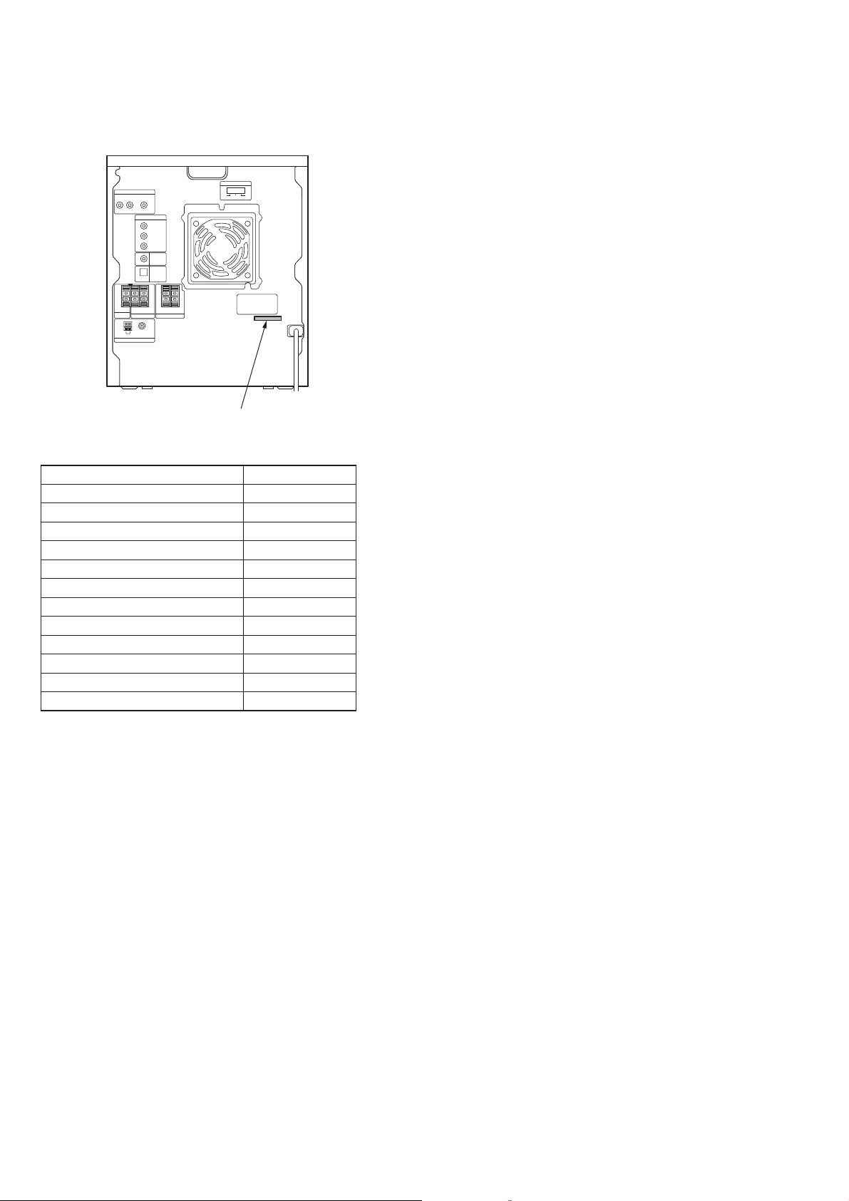
Manual Opening and Closing the CD Tray
As illustrated, insert a fl athead screwdriver and give a turn to the left to put the CD tray out.
Perform solder bridging to prevent damage by electrostatic
discharge when handling the BU as a single unit.
1
2
As illustrated, insert a flathead screwdriver
and give a turn to the left to put the tray out.
flathead screwdriver
CD tray
HCD-GZR88D/GZR99D
7
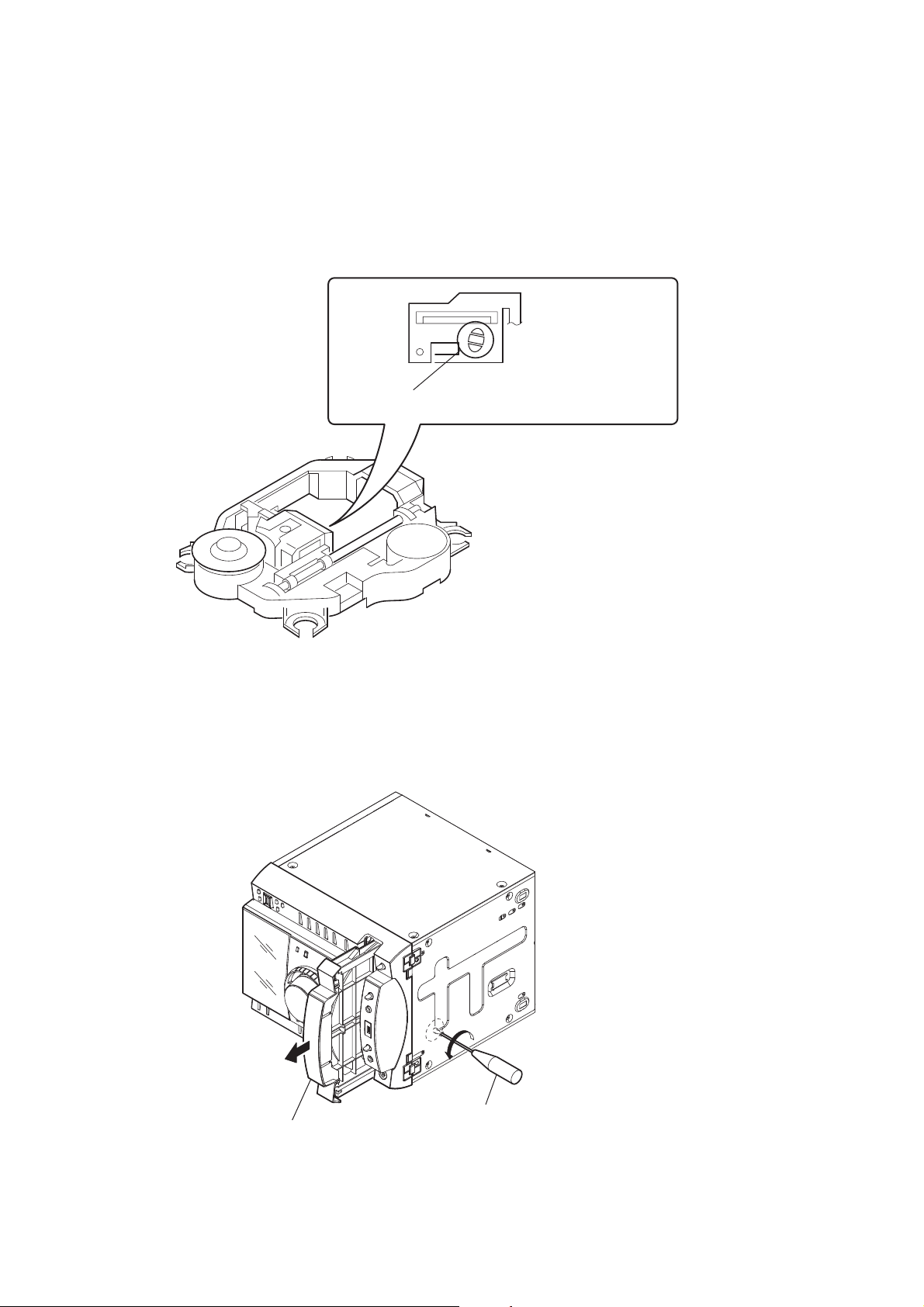
Service Position for the BU
DMB19 board
HCD-GZR88D/GZR99D
8
SECTION 2
DISASSEMBLY
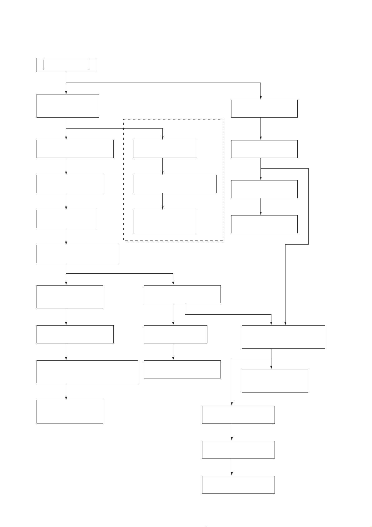
• This set can be disassembled in the order shown below.
2-1. CASE (SIDE-L),
CASE (SIDE-R)
(Page 9)
2-2. TOP PANEL SECTION
(Page 9)
SET
2-3. LOADING PANEL
(Page 10)
2-4. CHASSIS
(Page 10)
2-14. TC-AMP BOARD
(Page 15)
EXCEPT HCD-GZR99D: E2, E51, AR, MX MODEL
2-15. TAPE MECHANISM DECK
(Page 16)
2-16. LID (TC-L),
LID (TC-R)
(Page 16)
2-23. BASE UNIT
(Page 20)
2-24. OPTICAL PICK-UP
(Page 20)
2-21. CHASSIS
(Page 19)
2-22. DMB19 BOARD
(Page 19)
2-19. MOTOR (TB) BOARD
(Page 18)
2-20. MOTOR (LD) BOARD
(Page 18)
2-18. SENSOR BOARD
(Page 17)
2-5. FRONT PANEL SECTION
(Page 11)
2-11. PANEL (FL) SECTION
(Page 14)
2-10. MIC BOARD,
USB-LED BOARD
(Page 13)
2-12. LIQUID CRYSTAL DISPLAY PANEL
(LCD101)
(Page 14)
2-13. FRONT BOARD,
VOLUME BOARD
(Page 15)
2-7. MAIN BOARD
(Page 12)
2-6. BACK PANEL SECTION
(Page 11)
2-8. POWER AMP BOARD
(Page 12)
2-9. DVD MECHANISM DECK,
TUNER (TM901)
(Page 13)
2-17. DRIVER BOARD,
SW BOARD
(Page 17)
HCD-GZR88D/GZR99D
9
Note: Follow the disassembly procedure in the numerical order given.
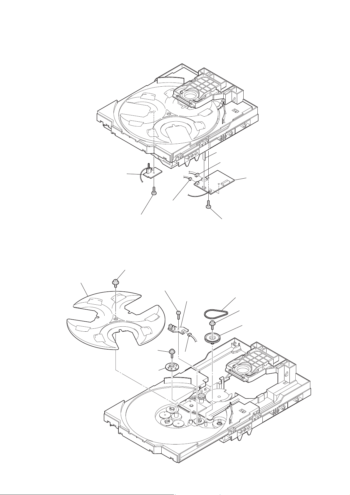
2-1. CASE (SIDE-L), CASE (SIDE-R)
2-2. TOP PANEL SECTION
1 screw
(+BVTP 3 u6)
1 screw
(+BVTP 3 u6)
0 top panel section
7 two hooks
8 top panel section
7 two hooks
4 claw
4 claw
8 wire (flat type) (11 core)
(CN102)
9 wire (flat type) (11 core)
(CN621)
5 claw
5 claw
2 screw
(+PWH 3 u8)
2 screw
(+PWH 3 u8)
3 screw
(+PWH 3 u8)
3 screw
(+PWH 3 u8)
6
6
HCD-GZR99D: E2, E51, AR, MX MODELEXCEPT HCD-GZR99D: E2, E51, AR, MX MODEL
1 three screws
(case 3 TP2)
2 three screws
(+P 3 u5)
5 case (side-L)
0 case (side-R)
6 three screws
(case 3 TP2)
7 three screws
(+P 3 u5)
3
8
9
4

HCD-GZR88D/GZR99D
10
2-3. LOADING PANEL
2-4. CHASSIS
3 loading panel
2
1
CD tray
flathead screwdriver
As illustrated, insert a flathead
screwdriver and give a turn to the left to
put the CD tray out.
1 screw
(+BVTP 3 u6)
6 CN1105 (4P)
2 two screws
(+BVTP 3 u8)
3 two screws
(+BVTP 3 u8)
5 chassis
7 wire (flat type) (5 core)
(CN704)
4
HCD-GZR88D/GZR99D
11
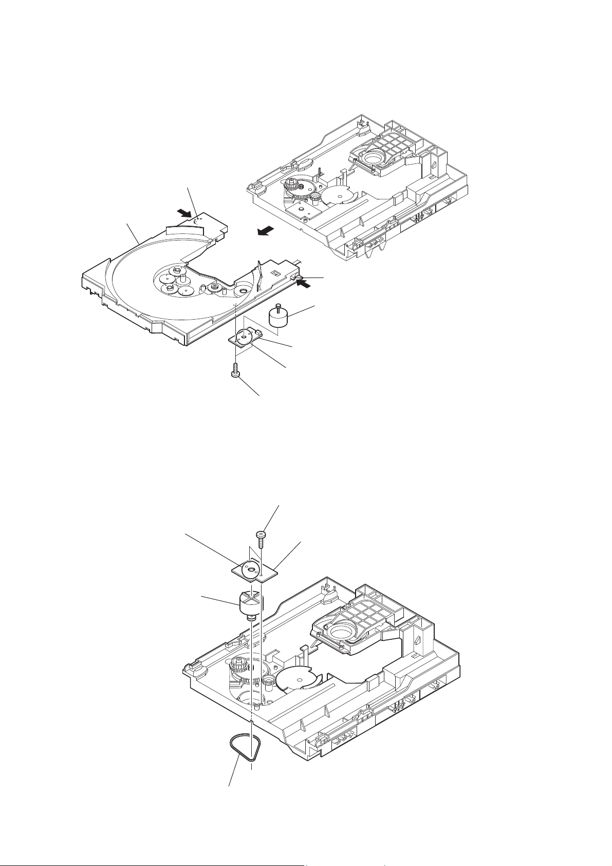
2-6. BACK PANEL SECTION
2-5. FRONT PANEL SECTION
6 screw
(+BVTP 3 u8)
7 screw
(+BVTP 3 u8)
8 screw
(+BVTP 3 u8)
9 two screws
(+BVTP 3 u8)
1 wire (flat type)
(7 core) (CN503)
2 wire (flat type)
(21 core) (CN501)
0 front panel section
3 CN407 (4P)
4 CN912 (4P)
5 CN1504 (3P)
5 two screws
(+BVTP 3 u6)
4 screw
(+BVTP 3 u6)
6 three screws
(+BVTP 3 u6)
7 two screws
(+BVTP 3 u6)
8 four screws
(+BVTP 3 u6)
qf back panel section
1 CN321 (2P)
qs CN1503
(3P)
qd CN602 (3P)
2 CN322 (5P)
3 CN324 (2P) (TH, AR, MX model)
CN323 (4P) (except TH, AR, MX model)
0 wire (flat type) (5 core)
(CN511)
qa wire (flat type) (7 core)
(CN1500)
9
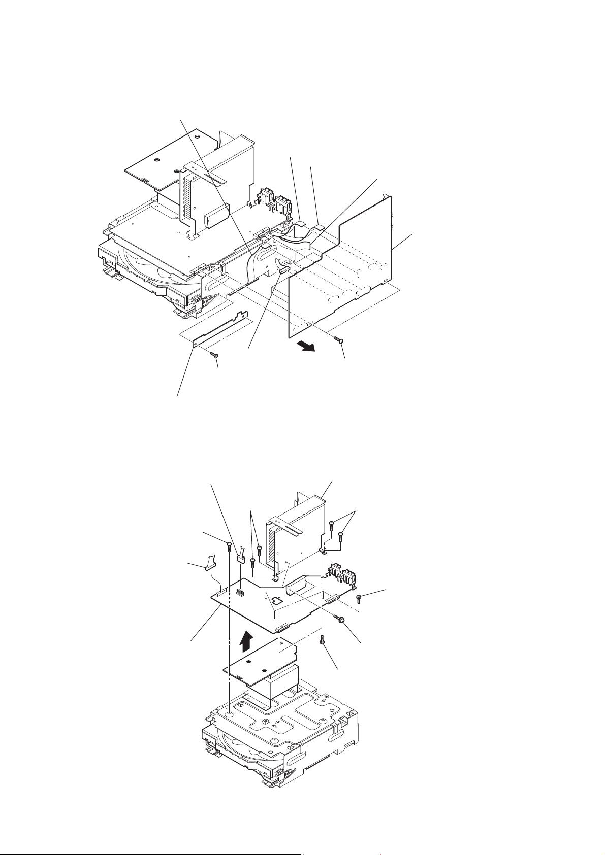
HCD-GZR88D/GZR99D
12
2-8. POWER AMP BOARD
2-7. MAIN BOARD
3 screw
(+BVTP 3 u8)
0 heat sink section
4 three screws
(+BVTP 3 u8)
9 two screws
(+BVTP 3 u8)
qa POWER AMP board
7 two screws
(+BVTP 3 u8)
6 two screws
(+BVTP 3 u8)
5 two screws
(transistor)
2 CN401 (5P)
1 CN402 (12P)
8
1 two screws
(+KTP2 3 u8)
3 two screws
(+BVTP 3 u8)
4
2 WIRE HOLDER C board
5 wire (flat type) (9 core)
(CN211)
6 wire (flat type) (7 core)
(CN191)
7 wire (flat type) (9 core)
(CN504)
0 MAIN board
8 wire (flat type) (13 core)
(CN641)
9 CN951 (9P)
HCD-GZR88D/GZR99D
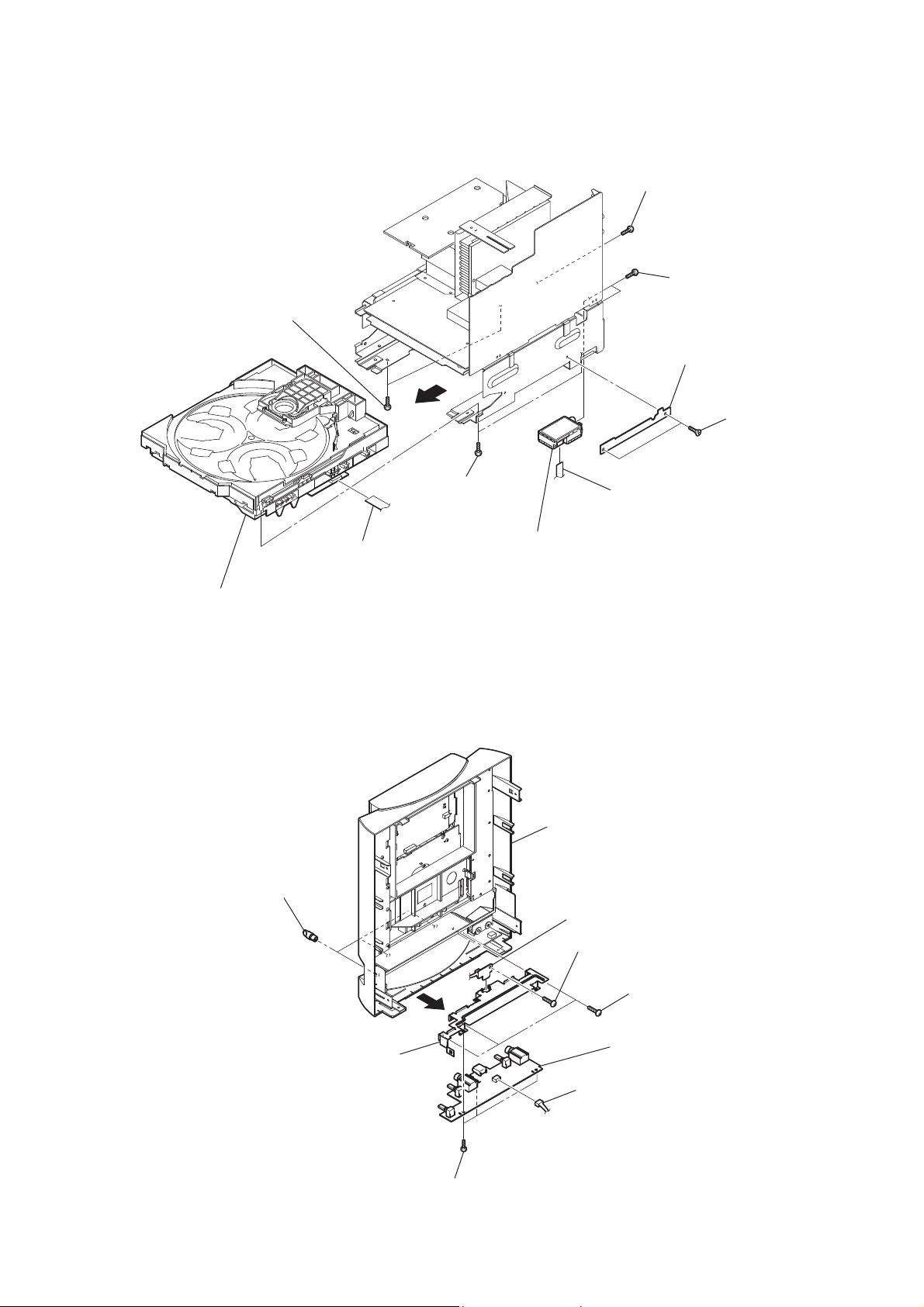
13
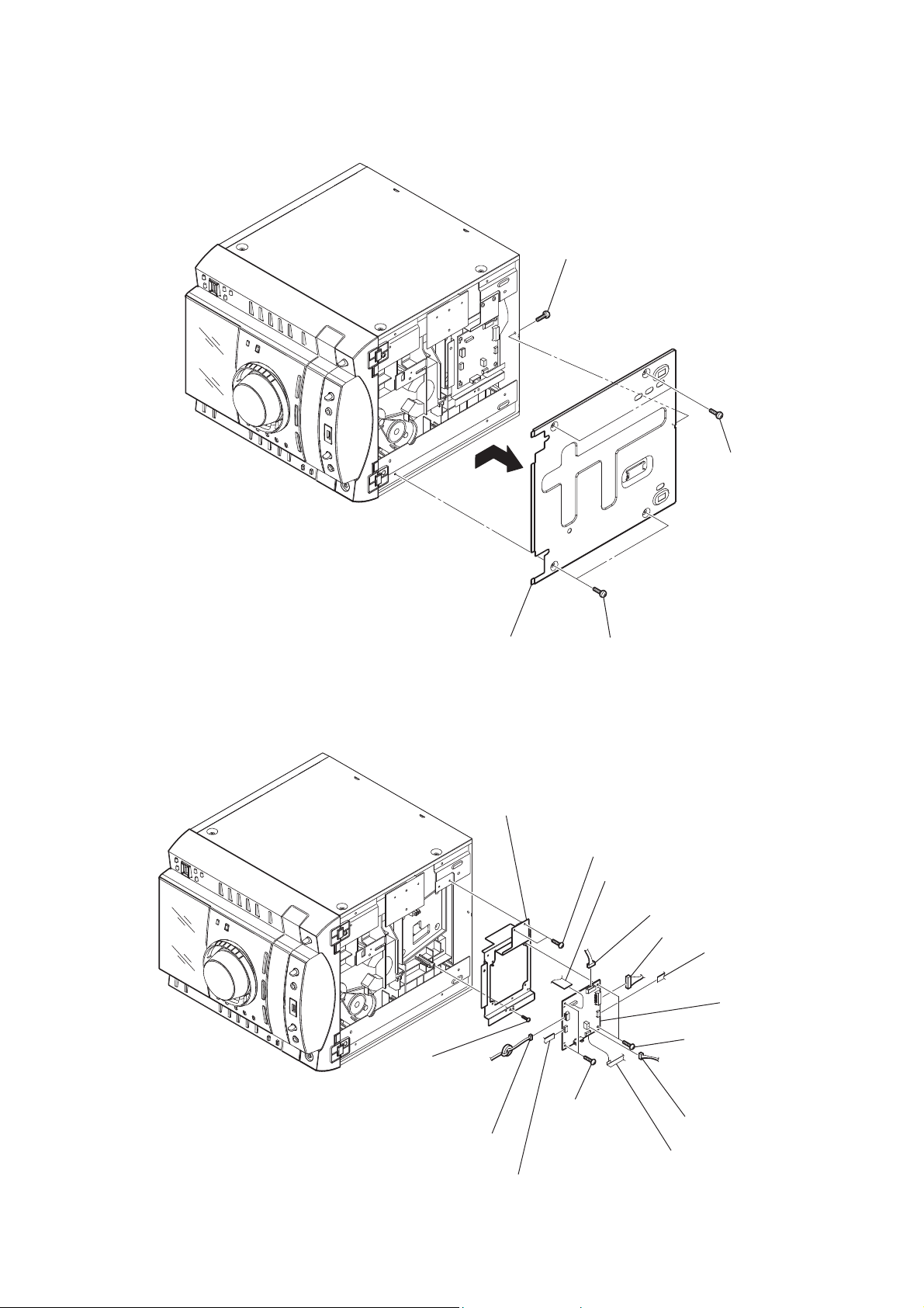
2-9. DVD MECHANISM DECK, TUNER (TM901)
2-10. MIC BOARD, USB-LED BOARD
8 MIC board
5 USB-LED board
holder (MIC PWB)
front panel section
7 CN704 (5P)
1 three knobs (MIC)
3 three screws
(+BVTP 2.6 (3CR))
6 three screws
(+BVTP 2.6 (3CR))
4
2 screw
(+BVTP 2.6 (3CR))
4 screw
(+BVTP 3 u8)
6 two screws
(+BVTP 3 u8)
9 two screws
(+BVTP 3 u6)
5 two screws
(+BVTP 3 u8)
1 two screws
(+KTP2 3 u8)
2 WIRE HOLDER C board
qa tuner (TM901)
3 wire (flat type) (13 core)
(CN701)
8 DVD MECHANISM DECK
7
0 wire (flat type) (9 core)
(connector)
HCD-GZR88D/GZR99D
14
2-12. LIQUID CRYSTAL DISPLAY PANEL (LCD101)
2-11. PANEL (FL) SECTION
1 CN861 (12P)
qf panel (FL) section
2 CN841 (10P)
3 claw
6 claw
7 claw
0 claw
qa claw
qs claw
qd
4 claw
5 claw
8 claw
9 claw
9 liquid crystal display panel
(LCD101)
2 CN003 (26 core)
1 CN004 (2P)
4 LCD CTRL board
6 holder (LCD-R)
8 holder (LCD-L)
3 two screws
(+BVTP 2.6 (3CR))
5 two screws
(+BVTP 2.6 (3CR))
7 two screws
(+BVTP 2.6 (3CR))
HCD-GZR88D/GZR99D
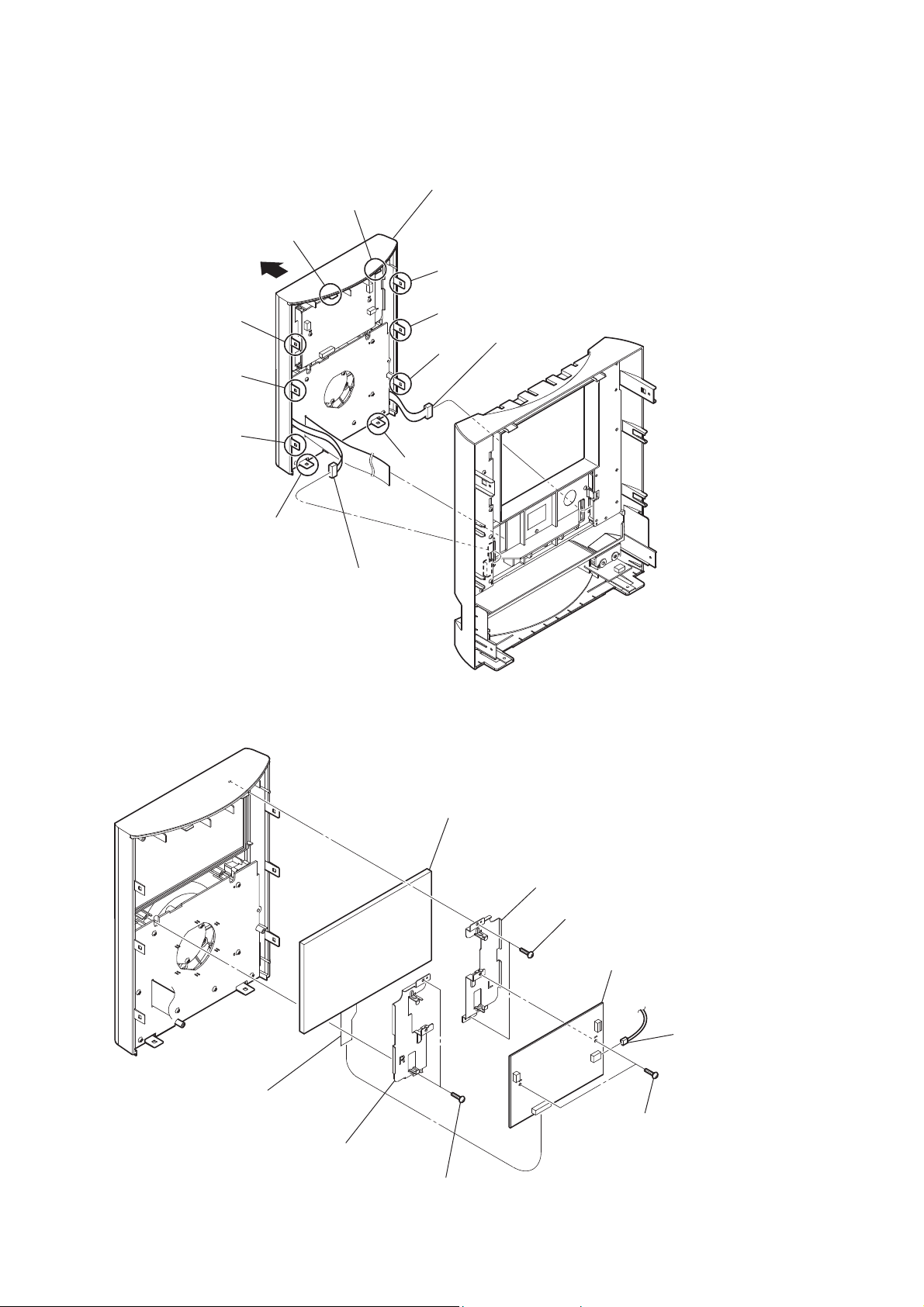
15
2-13. FRONT BOARD, VOLUME BOARD
2-14. TC-AMP BOARD (EXCEPT HCD-GZR99D: E2, E51, AR, MX, MODEL)
9 FRONT board
panel (LCD) assy
8 VOLUME board
1 knob (VOL) assy
2 nut
3 holder (knob)
4 knob (jog)
5 five screws
(+BVTP 2.6 (3CR))
6 four screws
(+BVTP 2.6 (3CR))
7 three screws
(+BVTP 2.6 (3CR))
1 CN1301 (3P)
2 CN1302 (8P)
4 TC-AMP board
3 three screws
(+BVTP 2.6 (3-CR))

HCD-GZR88D/GZR99D
16
2-16. LID (TC-L), LID (TC-R) (EXCEPT HCD-GZR99D: E2, E51, AR, MX, MODEL)
2-15. TAPE MECHANISM DECK (EXCEPT HCD-GZR99D: E2, E51, AR, MX, MODEL)
1 four screws
(+BVTP 2.6 (3-CR))
3 three screws
(+BVTP 2.6 (3-CR))
4 two screws
(+BVTP 2.6 (3-CR))
5 tape mechanism deck
2 shield (top)
1 damper
4 damper
2 spring (TC-R)
5 spring (TC-L)
3 lid (TC-R)
7 panel (top TC)
6 lid (TC-L)
HCD-GZR88D/GZR99D
17
2-17. DRIVER BOARD, SW BOARD
2-18. SENSOR BOARD
6 DRIVER board
2 SW board
3 CN704 (2P)
4 CN703 (4P)
7 CN702 (5 core)
5 two
screws
(+BTTP (M2.6))
1
screw
(+BTTP (M2.6))
2
tray
3
belt (table)
5
pulley (table)
8
screw
(+BTTP (M2.6))
9
SENSOR board
7
gear (geneva)
0
CN731
(3P)
1 floating
screw
(+PTPWH M2.6)
6 floating
screw
(+PTPWH M2.6)
4 floating
screw
(+PTPWH M2.6)
HCD-GZR88D/GZR99D
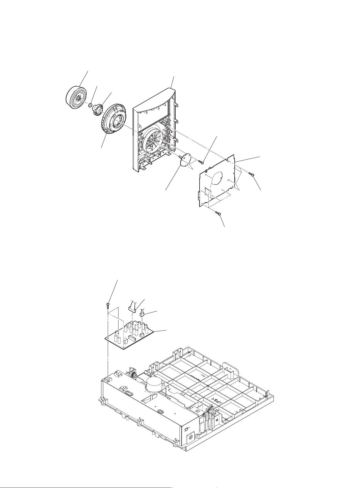
18
2-20. MOTOR (LD) BOARD
2-19. MOTOR (TB) BOARD
5
Remove the two solders of motor.
4
MOTOR (TB) board
2
stopper
2
stopper
6
table motor assy (M741)
table assy
3 two
screws
(+BTTP (M2.6))
1
4
Remove the two solders of motor.
3
MOTOR (LD) board
1
belt (loading)
5
loading motor assy (M751)
2 two
screws
(+BTTP (M2.6))
HCD-GZR88D/GZR99D
19
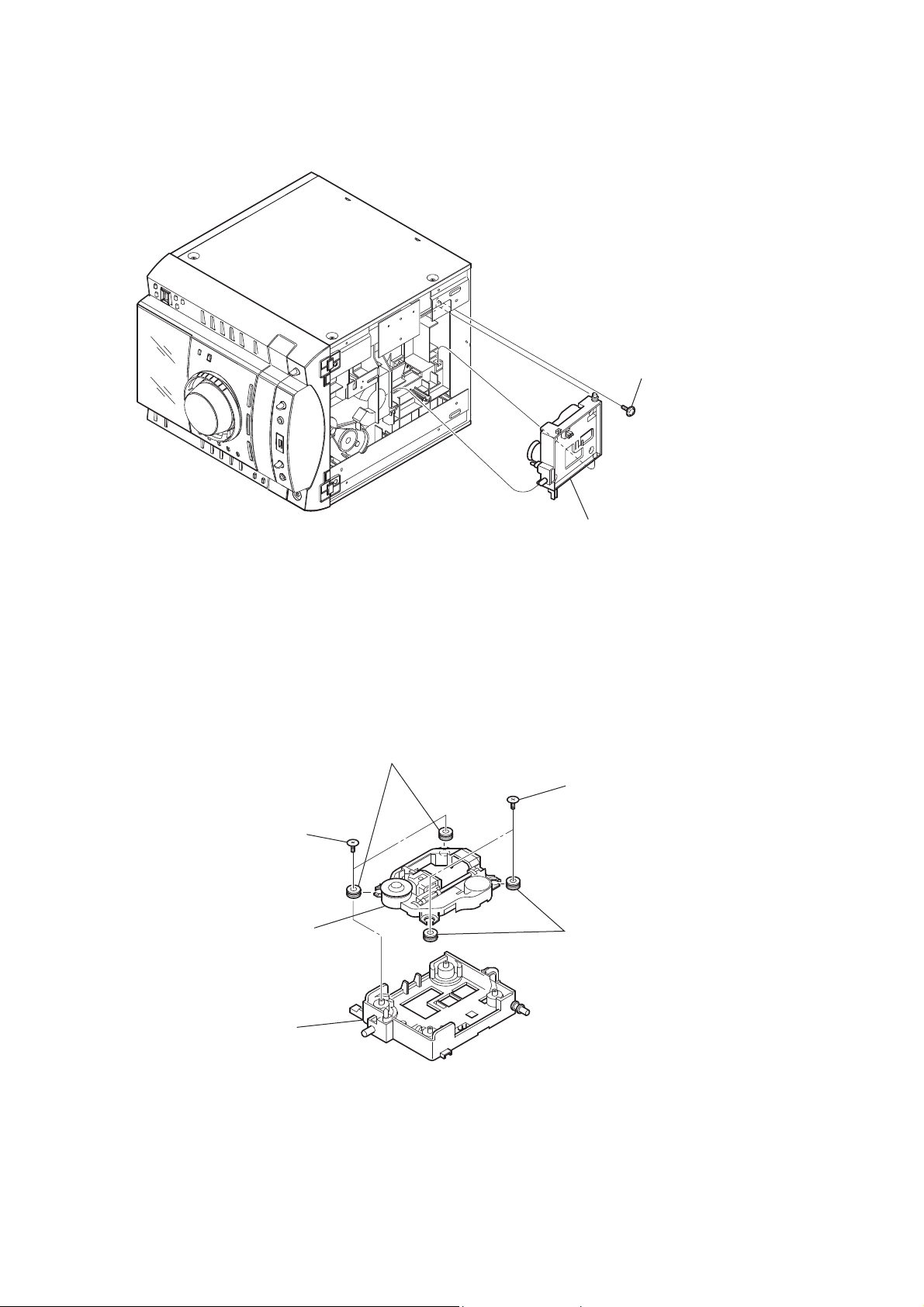
2-21. CHASSIS
2-22. DMB19 BOARD
1 screw
(+BVTP 3 u6)
2 two screws
(+BVTP 3 u8)
3 two screws
(+BVTP 3 u8)
5 chassis
4
9 two screws
(+BVTP 3 u8)
0 two screws
(+BVTP 3 u8)
qs two screws
(+BVTP 3 u8)
qd screw
(+BVTP 2.6 (3CR))
2 wire (flat type)(9 core)
(CN1106)
3 wire (flat type)(7 core)
(CN1104)
8 wire (flat type)(24 core)
(CN101)
qf bracket (DMB)
5 wire (flat type)(7 core)
(CN4602)
1 CN1105 (4P)
4 CN1103 (3P)
6 CN601 (9P)
qa DMB19 board
7 CN201 (6P)
HCD-GZR88D/GZR99D
20
2-24. OPTICAL PICK-UP
2-23. BASE UNIT
1 two insulator screws
3 two insulators
4 two insulators
2 two insulator screws
5
optical pick-up
6
holder (310)
1 screw
(+PTPWH M2.6)
2 base unit

HCD-GZR88D/GZR99D
21
SECTION 3
TEST MODE
[COLD RESET]
• The cold reset clears all data including preset data stored in the
RAM to initial conditions. Execute this mode when returning
the set to the customer.
Procedure:
1. Press the [
?/1
] button to turn on the system.
2. Press the [
x
] button, [DISC 3] button and [
?/1
] button
simultaneously.
3. The message “COLD RESET” appears on the liquid crystal
display panel. Then, the liquid crystal display panel becomes
blank for a while, and the system is reset.
[COMMON TEST MODE]
• This mode is used to check operations of the respective section
of Equalizer level, volume and VACS ON/OFF.
Procedure:
• To enter Common Test Mode
1. Press the [
?/1
] button to turn on the system.
2. Press the [
x
] button, [PRESET EQ] button and [DISC 1]
simultaneously.
3. The message “VACS0” appears on the liquid crystal
display panel.
• Check of Equalizer Level
1. Press the [EQ BAND/MEMORY] button repeatedly until a
message “ALL EQ MIN” appears on the liquid crystal
display panel. GEQ decreases to its minimum.
2. Press the [EQ BAND/MEMORY] button repeatedly until a
message “ALL EQ MAX” appears on the liquid crystal
display panel. GEQ increases to its maximum.
3. Press the [EQ BAND/MEMORY] button repeatedly until a
message “ALL EQ FLAT” appears on the liquid crystal
display panel. GEQ is set to fl at.
• Check of Volume
1. Press the [DISPLAY] button repeatedly, the sound volume
increases to its maximum and message “VOLUME16” t
“VOLUME MAX” appears on the liquid crystal display
panel.
2. Press the [OPTIONS] button repeatedly, the sound volume
decreases to its minimum and message “VOLUME16” t
“VOLUME MIN” appears on the liquid crystal display panel.
• Check of VACS (Variable Attenuation Control System)
ON/OFF Select
1. Press the [REC TO USB] button repeatedly until a message
“VACS OFF” or “VACS ON” appears on the liquid crystal
display panel.
• To release from Common Test Mode
1. To release from this mode, press the [
?/1
] button.
2. To cold reset is enforced at the same time.
[AMP TEST MODE]
• This mode is used to display the real time VACS level and
check operations of the respective sections of Equalizer band
and DBFB ON/OFF.
Procedure:
• To enter AMP Test Mode
1. Press the [
?/1
] button to turn on the system.
2. Press the [
x
] button, [GROOVE] button and [DISC 1] button
simultaneously.
3. The message “AMP TEST IN” appears of the liquid crystal
display panel.
• Check of VACS Display/AMP Adjustment Select
1. Press the [REC TO USB] button repeatedly until a message
“V0 0 0” appears on the liquid crystal display panel. “0”
represents VACS level which is triggered by signal level.
2. Press the [REC TO USB] button repeatedly until a message
“D +6 +2 +4” appears on the liquid crystal display panel.
“+6” represents Equalizer Low level, “+2” represents
Equalizer Mid level and “+4” represents Equalizer High
level.
• Check of Equalizer Band Select
1. Press the [EQ BAND/MEMORY] button repeatedly until a
message “LOW +6 dB” appears on the liquid crystal display
panel. EQ Band is set to Low level.
2. Press the [EQ BAND/MEMORY] button repeatedly until a
message “MID +2 dB” appears on the liquid crystal display
panel. EQ Band is set to Middle level.
3. Press the [EQ BAND/MEMORY] button repeatedly until a
message “HIGH +4 dB” appears on the liquid crystal display
panel. EQ Band is set to High level.
• Change of Equalizer Band
1. Press the [EQ BAND/MEMORY] button repeatedly until a
message “LOW +6 dB” appears on the liquid crystal display
panel.
2. When the [OPERATION DIAL] ring is turned clockwise
or counterclockwise even slightly, “LOW +6 dB” change
to “LOW –8 dB” y “LOW +8 dB” appears on the liquid
crystal display panel.
3. Press the [EQ BAND/MEMORY] button repeatedly until a
message “MID +2 dB” appears on the liquid crystal display
panel.
4. When the [OPERATION DIAL] ring is turned clockwise
or counterclockwise even slightly, “MID +2 dB” change to
“MID –8 dB” y “MID +8 dB” appears on the liquid crystal
display panel.
5. Press the [EQ BAND/MEMORY] button repeatedly until a
message “HIGH +4 dB” appears on the liquid crystal display
panel.
6. When the [OPERATION DIAL] ring is turned clockwise
or counterclockwise even slightly, “HIGH +4 dB” change
to “HIGH –8 dB” y “HIGH +8 dB” appears on the liquid
crystal display panel.
• Check of DBFB ON/OFF Select
1. Press the [OPTIONS] button repeatedly until a message
“DBFB OFF” or “DBFB ON” appears on the liquid crystal
display panel.
• To release from AMP Test Mode
1. To release from this mode, press the [
?/1
] button.

HCD-GZR88D/GZR99D
22
[TCM OFFLINE MODE]
(EXCEPT HCD-GZR99D: E2, E51, AR, MX, MODEL)
• This mode prevents the system from tuning off automatically
when TCM is not connected. Therefore, measurements can be
done even when TCM is not connected during production.
Procedure:
1. Press the [
?/1
] button to turn off the system and enter the
clock display or demonstration mode.
2. Press the [REC TO TAPE] button, [DISC 3] button and [
?/1
]
button simultaneously. The system will turn on automatically.
3. The message “TCM OFFLINE” appears on the liquid crystal
display panel.
• To release from TCM OFFLINE Mode
1. To release from this mode, press the [
?/1
] button.
[PANEL TEST MODE]
• This mode is used to check the liquid crystal display panel,
LEDs, button, MASTER VOLUME dial, OPERATION DIAL
ring, system software version, DVD lib version, model name
and destination.
Procedure:
1. Press the [
?/1
] button to turn on the system.
2. Press the [
x
] button, [DISC 3] button and [DISPLAY] button
simultaneously.
3. Power illuminator LEDs and segment in liquid crystal display
panel are lighted up.
4. When you want to enter to the system software version
display model, press the [DISC 1] button. The system
software version appears on the liquid crystal display panel.
Press the [DISC 1] button again, the DVD lib version appears
on the liquid crystal display panel.
5. Press the [DISC 2] button the mode name and destination on
the liquid crystal display panel.
6. Press the [DISC 3] button the key encode test mode is
activated.
7. In the key encode test mode, the liquid crystal display panel
displays “KEY 0 0 0 0 0”.
Each time a button pressed, change the each numbers.
• To release from Panal Test Mode
1. To release from this mode, press the [
x
] button, [DISC 3]
button and [DISPLAY] button simultaneously.
[DVD SHIP MODE (WITHOUT MEMORY CLEAR)]
• This mode moves the optical pick-up to the position durable to
vibration. Use this mode when returning the set to the customer
after repair.
Procedure:
1. Press the [
?/1
] button to turn on the system.
2. Press the [DVD] button, to set the “DVD NO DISC” mode.
3. Press the [
B
] button
(HCD-GZR99D: E2, E51, AR, MX model)
or [
Y
] button
(Except HCD-GZR99D: E2, E51, AR, MX model)
and [
?/1
] button simultaneously.
The system will turn off automatically.
4. After the “STANDBY” blinking display fi nishes, a message
“LOCK” appears on the liquid crystal display panel and
the DVD ship mode is set.
• To release from DVD Ship Mode
1. To release from this mode, press the [
?/1
] button.
[DVD SHIP MODE (WITH MEMORY CLEAR)]
• This mode moves the optical pick-up to the position durable
to vibration and clears all data including preset data stored in
the RAM to initial conditions after the power supply is turned
off. Use this mode when returning the set to the customer after
repair.
Procedure:
1. Press the [
?/1
] button to turn on the system.
2. Press the [DVD] button, to set the “DVD NO DISC” mode.
3. Press the [TUNING −] button, [DISC 3] button and [
?/1
]
button simultaneously.
4. After the “STANDBY” blinking display fi nishes, a message
“COLD RESET” appears on the liquid crystal display panel
and the DVD ship mode is set.
• To release from DVD Ship Mode
1. To release from this mode, press the [
?/1
] button.
[DISC THEFT PREVENTION MODE]
• This mode let you lock the disc tray. When this mode is
activated, the disc tray will not open.
Procedure:
1. Press the [
?/1
] button to turn on the system.
2. Press the [DVD] button.
3. Press the [
x
] button and [OPEN/CLOSE
Z
] button
simultaneously and hold down until “LOCKED” or
“UNLOCKED” appears on the liquid crystal display panel
(around 5 seconds).
• To release from Disc Theft Prevention Mode
1. This mode will not be deselected only by turning the power
off. To exit from the mode, perform the above item 4 again.
[DVD COLOR SYSTEM MODE]
• This mode let you change the color system of the video output
from PAL to NTSC or vice-versa.
Procedure:
1. Press the [
?/1
] button to turn on the system.
2. Press the [DVD] button.
3. Press the [
?/1
] button to turn off the system.
4. Press the [DISPLAY] button to switch the mode the clock
display or demonstration mode.
5. Press the [
X
] button and [
?/1
] button simultaneously.
The system will turn on automatically.
6. The message “COLOR PAL” or “COLOR NTSC” appears on
the liquid crystal display panel.
• To release from DVD Color System Mode
1. Once the color system has been selected, the mode is fi xed
there after. If you wish to change the mode again, perform
the above item 4 again.
[DVD FIRMWARE VERSION MODE]
• This mode is used to display the DVD fi rmware version.
Procedure:
1. Press the [
?/1
] button to turn on the system.
2. Press the [DVD] button.
3 Press the [
?/1
] button to turn off the system and enter the
clock display or demonstration mode.
4. Press the [
x
] button and [
?/1
] button simultaneously.
5. The version of DVD fi rmware appears on the on-screen
display on TV.

HCD-GZR88D/GZR99D
23
• To release from DVD Firmware Version Mode
1. To release from this mode, press the [
?/1
] button.
[MTK REBOOT AVOIDANCE MODE]
• This mode is used to display the MTK Reboot Avoidance.
Procedure:
1. Press the [
?/1
] button to turn on the system.
2. Press the [DVD] button.
3. Press the [DVD] button, [DISPLAY] button and [TUNING +]
button simultaneously.
• To release from MTK Reboot Avoidance Mode
1. To release from this mode, press the [
?/1
] button.
[AM TUNER STEP CHAGE]
• The step interval of AM channels can be toggled between 9
kHz and 10 kHz.
Procedure:
1. Press the [
?/1
] button to turn on the system.
2. Press the [TUNER/BAND] button repeatedly to select the
“AM”.
3. Press the [
?/1
] button to turn off the system.
4. Press the [TUNING +] button and [
?/1
] button
simultaneously.
The system will turn on automatically.
5. The message “AM 9k STEP” or “AM 10k STEP” appears
on the liquid crystal display panel and thus the channel step
change.
[VIDEO/SAT FUNCTION CHANGE]
• This mode let you change from VIDEO to SAT and vice-versa.
Procedure:
1. Press the [
?/1
] button to turn on the system.
2. Press the [VIDEO/SAT] button.
3. Press the [VIDEO/SAT] button and [
x
] button
simultaneously.
The function will change to SAT. Press the same button again
to change from SAT to VIDEO.
[DVD SERVICE MODE]
• This mode let you make diagnosis and adjustment easily by
using the remote commander and the TV. The instructions,
diagnostic results, etc. are given on the on-screen display.
• TEST DISC LIST
Be sure to use the DVD disc that matches the signal standards of
your region.
• CD
YEDS-18 (Part No.: 3-702-101-01)
PATD-012 (Part No.: 4-225-203-01)
• DVD SL (Single Layer)
NTSC : HLX-503 (Part No.: J-6090-069-A)
HLX-504 (Part No.: J-6090-088-A)
PAL : HLX-506 (Part No.: J-6090-077-A)
• DVD DL (Dual Layer)
NTSC : HLX-501 (Part No.: J-6090-071-A)
HLX-505 (Part No.: J-6090-089-A)
PAL : HLX-507 (Part No.: J-6090-078-A)
• Procedure to enter to DVD Service Mode:
1. Press the [
?/1
] button to turn on the system.
2. Press the [DVD] button.
3. Press the [
x
] button and [OPEN/CLOSE
Z
] button
simultaneously and then turn the [MASTER VOLUME] dial
clockwise.
4. The message “SERVICE IN” appears on the liquid crystal
display panel and the Top Menu of Remocon Diagnosis Menu
appears on the on-screen display on the TV. The model name,
main unit’s micom version information (IF-con) and DVD
fi rmware version information (Syscon) are displayed at the
bottom of the on-screen display.
5. To execute each function, press its number by using numeric
button on the remote commander.
6. To release from this mode, press the [
?/1
] button to turn off
the system.
• Execute IOP Measurement
In order to execute IOP measurement, the following standard
procedures must be followed.
1. From the Top Menu of Remocon Diagnosis Menu, select “2.
Drive Manual Operation” by pressing the [2] button on the
remote commander. The following screen appears on the on-
screen display.
2. Select “3. Manual Adjustment” by pressing the [3] button on
the remote commander. The following screen appears on the
on-screen display.
Remocon Diagnosis Menu
0. External Chip Check
1. Servo Parameter Check
2. Drive Manual Operation
3. Emergency History
4. Version Information
Model Name
IF-con
Syscon
: STX5DS_E2
: Ver. 01.00 (0000)
: Ver. 1.200
Drive Manual Operation
1. Servo Control
2. Track/Layer Jump
3. Manual Adjustment
4. Mecha test mode
5. MIRR time Adjust
0. Return to Top Menu
Manual Adjust
1. Track Balance Adjust:
2. Track Gain Adjust:
3. Focus Balance Adjust:
4. Focus Gain Adjust:
5. Eg Boost Adjust:
6. Iop:
7. TRV. Level:
8. S curve (FE) Level:
9. RFL (PI) Level:
0. MIRR Time:
O o Change Value
RETURN Return to previous menu
HCD-GZR88D/GZR99D
24
3. Select “6. Iop:” by pressing the[6] button on the remote
commander.
4. Wait until a hexadecimal number appears in the on-screen
display as below:
5. Convert data from hexadecimal to decimal by using
conversion table.
6. Please fi nd the label on the rear of the BU (Base Unit).
The default IOP value is written in the label.
7. Subtract between these two values.
8. If the remainder is smaller than 93 (decimal), then it is OK.
However if the value is higher than 93, then the BU is
defective and need to be change.
9. Press the[RETURN] button on the remote commander to
return to previous menu.
10. Press the[0] button on the remote commander to return to the
Top Menu of Remocon Diagnosis Menu.
11. Press the[
?/1
] button to turn off the system.
• Check Emergency History
To check the emergency history, please follow the following
procedure.
1. From the Top Menu of Remocon Diagnosis Menu, select “3.
Emergency History” by pressing the [3] button on the remote
commander. The following screen appears on the on-screen
display.
2. You can check the total time when the laser is turned on
during playback of DVD and CD from the above menu. The
maximum time, which can be displayed are 999h 59min.
3. You can check the error code of latest 10 emergency history
from the above menu. To view the previous or next page of
emergency history, press the[
.
] button or [
>
] button
on the remote commander. The error code consists of
• Error Code
The meaning of error code is as below:
01: Communication error (No reply from syscon)
02: Syscon hung up
03: Power OFF request when syscon hung up
19: Thermal shutdown
24: MoveSledHome error
25: Mechanical move error (5 Changer)
26: Mechanical move stack error
30: DC motor adjustment error
31: DPD offset adjustment error
32: TE balance adjustment error
33: TE sensor adjustment error
34: TE loop gain adjustment error
35: FE loop gain adjustment error
36: Bad jitter after adjustment
40: Focus NG
42: Focus layer jump NG
52: Open kick spindle error
51: Spindle stop error
60: Focus on error
61: Seek fail error
62: Read Q data/ID error
70: Lead in data read fail
71: TOC read time out (CD)
80: Can’t buffering
81: Unknown media type
• Parameter of error code
This is the detail of error code.
• Time of error code
This is the laser time when an error occurred.
To clear the Laser Hours
Press the [ DISPLAY] button and then press the [CLEAR]
button. The data for both CD and DVD data are reset.
Manual Adjust
1. Track Balance Adjust:
2. Track Gain Adjust:
3. Focus Balance Adjust:
4. Focus Gain Adjust:
5. Eg Boost Adjust:
6. Iop. ED
7. TRV. Level:
8. S curve (FE) Level:
9. RFL (PI) Level:
0. MIRR Time:
O o Change Value
RETURN Return to previous menu
Emg. History Check
1. 01 05 04 04
Laser Hours CD 999h 59min
DVD 999h 59min
00 92 46 00
00 00 00 00
00 00 23 45
2. 02 02 01 01 00 A9 4B 00
00 00 00 00
00 00 23 45
Next Next Page Prev Prev Page
O Return to Top Menu
Example of Error code
1. 01 05 04 04 00 92 46 00
00 00 00 00 00 00 23 45
Example of Error code
1. 01 05 04 04 00 92 46 00
00 00 00 00 00 00 23 45
Example of Error code
1. 01 05 04 04 00 92 46 00
00 00 00 00 00 00 23 45
Emg. History Check
1. 01 05 04 04
Laser Hours CD 0h 0min
DVD 0h 0min
00 92 46 00
00 00 00 00 00 00 23 45
2. 02 02 01 01 00 A9 4B 00
00 00 00 00 00 00 23 45
Next Next Page Prev Prev Page
O Return to Top Menu
HCD-GZR88D/GZR99D
25
To clear the Emergency History
Press the [DVD TOP MENU] button and then press the
[CLEAR] button.
The error code for all emergency history would be reset.
To clear the Initialize Setup Data
Press the [DVD/TUNER MENU] button and then press the
[CLEAR] button on the remote commander.
To return to the Top Menu of Remocon Diagnosis Menu
Press the [0] button on the remote commander.
• Check Version Information
To check the version information, please follow the following
procedure.
1. From the Top Menu of Remocon Diagnosis Menu, select “4.
Version Information” by pressing the [4] button on the remote
commander. The following screen appears on the on-screen
display.
To return to the Top Menu of Remocon Diagnosis Menu,
press the [0] button on the remote commander.
Emg. History Check
1. 00 00 00 00
Laser Hours CD 999h 59min
DVD 999h 59min
00 00 00 00
00 00 00 00
00 00 00 00
2. 00 00 00 00 00 00 00 00
00 00 00 00 00 00 00 00
Next Next Page Prev Prev Page
O Return to Top Menu
Version information
O Return to Top Menu
Firm (Main) : Ver. xxxxx
Firm (Sub) : xxxxx
RISC : xxxxx
8032 : xxxxx
Audio DSP : xxxxx
Servo DSP : xxxxx
Emg. History Check
Initialize setup data...
Laser Hours CD
999h 59min
DVD 999h 59min
Next Next Page Prev Prev Page
O Return to Top Menu

HCD-GZR88D/GZR99D
26
SECTION 4
MECHANICAL ADJUSTMENTS
Except HCD-GZR99D: E2, E51, AR, MX Model:
Precaution
1. Clean the following parts with a denatured alcohol-moistened
swab:
record/playback heads pinch rollers
erase head rubber belts
capstan idlers
2. Demagnetize the record/playback head with a head
demagnetizer.
3. Do not use a magnetized screwdriver for the adjustments.
4. After the adjustments, apply suitable locking compound to
the parts adjusted.
5. The adjustments should be performed with the rated power
supply voltage unless otherwise noted.
Torque Measurement
Mode Torque meter Meter reading
FWD CQ-102C
3.06 N • m to 6.96 N • m
31 to 71 g • cm
(0.43 – 0.98 oz • inch)
FWD
back tension
CQ-102C
0.19 N • m to 0.58 N • m
2 to 6 g • cm
(0.02 – 0.08 oz • inch)
REV CQ-102RC
3.06 N • m to 6.96 N • m
31 to 71 g • cm
(0.43 – 0.98 oz • inch)
REV
back tension
CQ-102RC
0.19 N • m to 0.58 N • m
2 to 6 g • cm
(0.02 – 0.08 oz • inch)
FF/REW CQ-201B
6.96 N • m to 14.02 N • m
71 to 143 g • cm
(0.98 – 1.99 oz • inch)
FWD tension CQ-403A
9.80 N • m
100 g or more
(3.53 oz or more)
REV tension CQ-403R
9.80 N • m
100 g or more
(3.53 oz or more)
HCD-GZR88D/GZR99D
27
Checking Location: DMB19 board (Side A)
SECTION 5
ELECTRICAL ADJUSTMENTS
When the optical pick-up assy is replaced, perform the “Execute
IOP Measurement”.
Execute IOP Measurement (See page 23)
[TEST DISC LIST]
Be sure to use the DVD disc that matches the signal standards of
your region.
• CD
YEDS-18 (Part No.: 3-702-101-01)
PATD-012 (Part No.: 4-225-203-01)
• DVD SL (Single Layer)
NTSC : HLX-503 (Part No.: J-6090-069-A)
HLX-504 (Part No.: J-6090-088-A)
PAL : HLX-506 (Part No.: J-6090-077-A)
• DVD DL (Dual Layer)
NTSC : HLX-501 (Part No.: J-6090-071-A)
HLX-505 (Part No.: J-6090-089-A)
PAL : HLX-507 (Part No.: J-6090-078-A)
[RFMON Level Check]
Connection:
Procedure:
1. Connect an oscilloscope to CN105 pin 6 (RFMON) and
CN105 pin 3 (GND) on the DMB19 board.
2. Turn the power on.
3. Set the test disc (refer to the TEST DISC LIST) on the tray
and press the [
B
] button
(HCD-GZR99D: E2, E51, AR, MX model)
or [
Y
] button
(Except HCD-GZR99D: E2, E51, AR, MX model)
to playback.
4. Confi rm that oscilloscope waveform is clear and check
RFMON signal level is correct or not.
Note: A clear RFMON signal waveform means that the shape
“◊” can be clearly distinguished at the center of the
waveform.
FM Tune Level Check
Procedure:
1. Turn on the set.
2. Input the following signal from signal generator to FM
antenna input directly.
Carrier frequency: A = 87.5 MHz, B = 98 MHz, C = 108 MHz
Deviation : 75 kHz
Modulation : 1 kHz
ANT input : 35 dBμ (EMF)
Note: Use 75 ohm coaxial cable to connect signal generator and
the set.
You cannot use video cable for checking.
Use signal generator whose output impedance is 75 ohm.
3. Set to FM tuner function and tune A, B and C signals.
4. Confi rm “TUNED” is lit on the display for A, B and C
signals.
When the selected station signal is received in good condition,
“TUNED” is displayed.
DVD SECTION
TUNER SECTION
+
–
CN105 pin 6 (RFMON)
CN105 pin 3 (GND)
oscilloscope
DMB19 board
RFMON signal waveform
VOLT/DIV: 200 mV
TIME/DIV: 500 nS
level: 0.58 ± 1.23 Vp-p (DVD)
0.57 ± 1.1 Vp-p (CD)
CN105 pin 3
(GND)
CN105 pin 6
(RFMON)
– DMB19 BOARD (SIDE A) –
IC104
CN105
CN1104
IC101
CN1103
set
signal
generator

HCD-GZR88D/GZR99D
28
Video Level Check (VIDEO BOARD)
Purpose
This adjustment is made to satisfy the NTSC standard, and if not
adjusted correctly, the brightness will be too large or small.
Procedure:
1. Connect oscilloscope to VIDEO OUT jack.
2. Load a DVD reference disc playback.
3. Check the video signal level is 1.00±0.07Vp-p.
VIDEO SECTION
Except HCD-GZR99D: E2, E51, AR, MX Model:
1. Demagnetize the record/playback head with a head
demagnetizer.
2. Do not use a magnetized screwdriver for the adjustments.
3. After the adjustments, apply suitable locking compound to
the parts adjust.
4. The adjustments should be performed with the rated power
supply voltage unless otherwise noted.
5. The adjustments should be performed in the order given in
this service manual. (As a general rule, playback circuit
adjustment should be completed before performing recording
circuit adjustment.)
6. The adjustments should be performed for both L-CH and
R-CH.
7. Switches and controls should be set as follows unless
otherwise specifi ed.
• Test Tape
Tape Signal Used for
P-4-A063 6.3 kHz, –10 dB Azimuth Adjustment
Record/Playback Head Azimuth Adjustment
DECK B
Note: Perform this adjustments for both decks
Procedure:
1. Mode: Playback
2. Turn the adjustment screw and check output peaks. If the
peaks do not match for L-CH and R-CH, turn the adjustment
screw
so that outputs match within 1dB of peak.
DECK SECTION
0 dB = 0.775V
oscilloscope
set
J1502
VIDEO OUT
75 ȍ
+
–
1.00 ± 0.07 Vp-p
(WHITE 100%)
+
–
level meter
test tape
P-4-A063
(6.3 kHz, –10 dB)
MAIN board
IC101
pin wh (L-CH)
pin ql (R-CH)
MAIN board
IC101
pin t; (GND)
screw
position
L-CH
peak
within
1 dB
output
level
L-CH
peak
R-CH
peak
within
1 dB
screw
position
R-CH
peak
HCD-GZR88D/GZR99D
29
3. Mode: Playback
4. After the adjustments, apply suitable locking compound to
the pats adjusted.
Adjustment Location: Record/Playback/Erase Head (Deck B)
oscilloscope
waveform of oscilloscope
in phase
good wrong
45° 90° 135° 180°
V
R
L
R-CH
L-CH
H
test tape
P-4-A063
(6.3 kHz, –10 dB)
MAIN
board
IC101
pin wh
pin t;
pin ql
reverse
forward

HCD-GZR88D/GZR99D
30
SECTION 6
DIAGRAMS
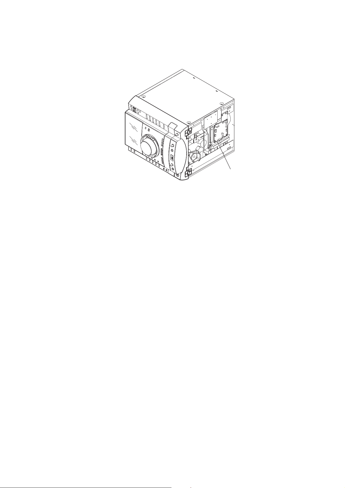
• Circuit Boards Location
VOLUME board
FRONT board
LCD CTRL board
TC-AMP board
(except HCD-GZR99D: E2, E51, AR, MX model)
DMB19 board
DRIVER board
SW board
SENSOR board
TRANS-SUB board
VIDEO board
MOTOR (LD) board
MOTOR (TB) board
MIC board
USB-LED board
HP board
LEFT board
RIGHT board
POWER AMP board
MAIN board
TRANS board
 Loading...