


HCD-SHAKE33
Table of contents
 Loading...
Sony HCD-SHAKE33, HCD-SHAKE44, HCD-SHAKE55, HCD-SHAKE66, HCD-SHAKE77 Schematic
...
HCD-SHAKE33/SHAKE44/SHAKE55/
SHAKE66/SHAKE77/SHAKE88
SERVICE MANUAL
Ver. 1.4 2014.12
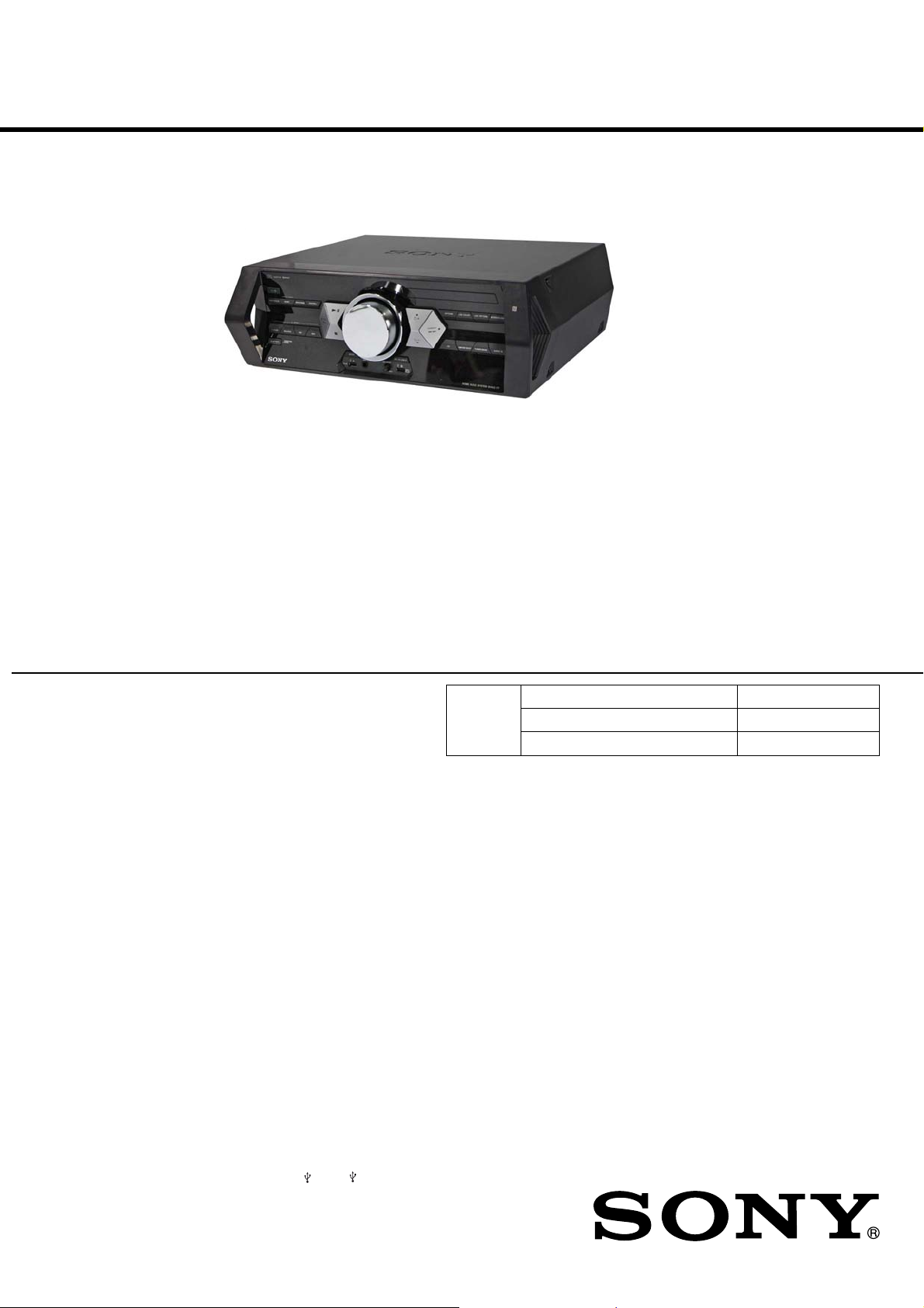
Photo: HCD-SHAKE77
• HCD-SHAKE33 is the tuner, USB, CD player, Bluetooth, NFC and
amplifier section in SHAKE-33.
• HCD-SHAKE55 is the tuner, USB, CD player, Bluetooth, NFC and
amplifier section in SHAKE-55.
• HCD-SHAKE77 is the tuner, USB, CD player, Bluetooth, NFC and
amplifier section in SHAKE-77.
• HCD-SHAKE44 is the tuner, USB, CD/DVD player, Bluetooth, NFC
and amplifier section in SHAKE-44D.
• HCD-SHAKE66 is the tuner, USB, CD/DVD player, Bluetooth, NFC
and amplifier section in SHAKE-66D.
• HCD-SHAKE88 is the tuner, USB, CD/DVD player, Bluetooth, NFC
and amplifier section in SHAKE-88D.
US Model
HCD-SHAKE33/SHAKE55
AEP Model
UK Model
HCD-SHAKE33
Russian Model
HCD-SHAKE66
E Model
HCD-SHAKE33/SHAKE44/SHAKE55/
SHAKE66/SHAKE77/SHAKE88
Argentina Model
Mexican Model
HCD-SHAKE33/SHAKE55/SHAKE77
Australian Model
HCD-SHAKE77
Malaysia Model
HCD-SHAKE44/SHAKE66/SHAKE88
Saudi Arabia Model
South African Model
Thai Model
HCD-SHAKE44/SHAKE88
AUDIO POWER SPECIFICATIONS
POWER OUTPUT AND TOTAL HARMONIC
DISTORTION:
(US model only)
SHAKE-55
With 4 ohm loads, both channels driven, from
120 – 10,000 Hz; rated 180 watts per channel
minimum RMS power, with no more than 0.7%
total harmonic distortion from 250 milliwatts to
rated output.
SHAKE-33
With 4 ohm loads, both channels driven, from
40 – 600 Hz; rated 180 watts per channel minimum
RMS power, with no more than 0.7% total
harmonic distortion from 250 milliwatts to rated
output.
Amplifi er section
The following are measured at
US model:
AC 120 V, 60 Hz
MX model:
AC 120 V – 240 V, 60 Hz
AEP, UK, RU model:
AC 220 V – 240 V, 50/60 Hz
E51 model:
AC 220 V – 240 V, 50 Hz
Other models:
AC 120 V – 240 V, 50/60 Hz
SHAKE-77/88D
WF (Woofers)/MID (Mid speakers)/TW (Tweeters)
Power Output (rated):
350 W + 350 W (at 4 ohms, 1 kHz,
1% THD)
RMS output power (reference):
600 W + 600 W (per channel at
4 ohms, 1 kHz)
9-890-648-05
2014L80-1
2014.12
©
Sony Corporation
Published by Sony EMCS (Malaysia) PG Tec
CD/DVD
Section
SPECIFICATIONS
SW (Subwoofers)
RMS output power (reference):
1,200 W + 1,200 W (per channel at
8 ohms, 100 Hz)
SHAKE-55/66D
WF (Woofers)/TW (Tweeters)
Power Output (rated):
350 W + 350 W (at 4 ohms, 1 kHz,
1% THD)
RMS output power (reference):
600 W + 600 W (per channel at
4 ohms, 1 kHz)
SW (Subwoofers)
RMS output power (reference):
900 W + 900 W (per channel at
10 ohms, 100 Hz)
SHAKE-33/44D
WOOFERS
Power Output (rated):
350 W + 350 W (at 4 ohms, 100 Hz,
1% THD)
RMS output power (reference):
600 W + 600 W (per channel at
4 ohms, 100 Hz)
MID (Mid speakers)/TWEETERS
RMS output power (reference):
500 W + 500 W (per channel at
5 ohms, 1 kHz)
Inputs
AUDIO IN 1/PARTY CHAIN IN L/R
Voltage 2 V, impedance 47 kilohms
AUDIO IN 2 L/R
Voltage 2 V, impedance 47 kilohms
MIC (SHAKE-55/77 only)
Sensitivity 1 mV, impedance 10 kilohms
MIC 1, MIC 2 (SHAKE-44D/66D/88D)
Sensitivity 1 mV, impedance 10 kilohms
(USB) A, (USB) B port
Type A
Model Name Using Similar Mechanism NEW
CD Mechanism Type CDM90-DVBU202//M
Optical Pick-up Name CMS-S76RFS7G
Outputs
AUDIO OUT/PARTY CHAIN OUT L/R
Voltage 2 V, impedance 1 kilohm
VIDEO OUT (SHAKE-44D/66D/88D)
Max. output level 1 Vp-p, unbalanced,
Sync. negative load impedance
75 ohms
USB section
Supported bit rate
WMA:
48 kbps – 192 kbps, VBR, CBR
AAC:
48 kbps – 320 kbps, VBR, CBR
Sampling frequencies
WMA: 44.1 kHz
AAC: 44.1 kHz
Supported USB device
Mass Storage Class
Maximum current
500 mA
Disc/USB section
Supported bit rate
MPEG1 Layer-3:
32 kbps – 320 kbps, VBR
MPEG2 Layer-3:
8 kbps – 160 kbps, VBR
MPEG1 Layer-2:
32 kbps – 384 kbps, VBR
Sampling frequencies
MPEG1 Layer-3:
32 kHz/44.1 kHz/48 kHz
MPEG2 Layer-3:
16 kHz/22.05 kHz/24 kHz
MPEG1 Layer-2:
32 kHz/44.1 kHz/48 kHz
Xvid (SHAKE-44D/66D/88D)
Video codec: Xvid video
Bit rate: 4.854 Mbps (MAX)
Resolution/Frame rate:
720 × 480 30 fps
720 × 576 25 fps
Audio codec: MP3
MPEG4 (SHAKE-44D/66D/88D)
File format: MP4 File Format
Video codec:
MPEG4 Simple Profile
(AVC is not compatible.)
Bit rate: 4 Mbps
Resolution/Frame rate:
720 × 576 30 fps
Audio codec: AAC-LC
(HE-AAC is not compatible.)
DRM: Not compatible
Disc player section
System
Compact disc and digital audio system
Laser Diode Properties
Emission Duration: Continuous
Laser Output*: Less than 44.6 μW
* This output is the value measurement
at a distance of 200 mm from the
objective lens surface on the Optical
Pick-up Block with 7 mm aperture.
Frequency response
20 Hz – 20 kHz
– Continued on next page –
HOME AUDIO SYSTEM
HCD-SHAKE33/SHAKE44/SHAKE55/SHAKE66/SHAKE77/SHAKE88
Ver. 1.2
Signal-to-noise ratio (SHAKE-33/55/77)
More than 90 dB
Dynamic range (SHAKE-33/55/77)
More than 88 dB
Video color system format (SHAKE-44D/66D/88D)
NTSC and PAL
Tuner section
FM stereo, FM/AM superheterodyne tuner
Antenna:
FM lead antenna
AM loop antenna
FM tuner section
Tuning range
model:
US
87.5 MHz – 108.0 MHz (100 kHz step)
Other models:
87.5 MHz – 108.0 MHz (50 kHz step)
AM tuner section
Tuning range
AEP, UK, RU model:
531 kHz – 1,602 kHz (9 kHz step)
AUS, E2, E51, US, MX, AR models:
531 kHz – 1,710 kHz (9 kHz step)
530 kHz – 1,710 kHz (10 kHz step)
Other models:
531 kHz – 1,602 kHz (9 kHz step)
530 kHz – 1,610 kHz (10 kHz step)
Bluetooth section
Communication system
Bluetooth Standard version 3.1
Output
Bluetooth Standard Power Class 2
Maximum communication range
Line of sight approx. 10m
Frequency band
2.4 GHz band (2.4000 GHz – 2.4835 GHz)
Modulation method
FHSS (Freq Hopping Spread Spectrum)
Compatible Bluetooth profiles
A2DP (Advanced Audio Distribution
Profile)
AVRCP 1.3 (Audio Video Remote
Control Profile)
SPP (Serial Port Profile)
Supported codecs
SBC (Sub Band Codec)
AAC (Advanced Audio Coding)
1)
The actual range will vary depending on
factors such as obstacles between devices,
magnetic fields around a microwave oven,
static electricity, reception sensitivity,
antenna’s performance, operating system, software application, etc.
2)
Bluetooth standard profiles indicate the
purpose of Bluetooth communication
between devices.
General
Power requirements
US model:
AC 120 V, 60 Hz
MX model:
AC 120 V – 240 V, 60 Hz
AEP, UK, RU model:
AC 220 V – 240 V, 50/60 Hz
E51 model:
AC 220 V – 240 V, 50 Hz
Other models:
AC 120 V – 240 V, 50/60 Hz
Power consumption
SHAKE-77/88D: 525 W
SHAKE-55/66D: 500 W
SHAKE-33/44D: 350 W
Power consumption (at the Power Saving mode)
0.5 W (When “BT STANDBY” is set to
“STANDBY OFF”)
4 W (When “BT STANDBY” is set to
“STANDBY ON”)
Dimensions (w/h/d) (excl. speakers)
(Approx.)
505 mm × 160 mm × 350 mm
(20 in × 6
Mass (excl. speakers) (Approx.)
SHAKE-55/66D/77/88D: 7.6 kg
(16 lb 13 oz)
SHAKE-33/44D: 7.0 kg (15 lb 7 oz)
Supplied accessories
Remote control (1)
R6 (Size AA) batteries (2)
FM lead/AM loop antenna (1)
Bottom panel (1)
Design and specifications are subject to change
without notice.
3
⁄8 in × 13 7⁄8 in)
1)
2)
License and Trademark Notice
is a trademark of DVD Format/Logo
•
Licensing Corporation.
• “DVD+RW”, “DVD-RW”, “DVD+R”,
“DVD-R”, “DVD VIDEO”, and the “CD” logos
are trademarks.
• MPEG Layer-3 audio coding technology and
patents licensed from Fraunhofer IIS and
Thomson.
• Windows Media is either a registered trademark
or trademark of Microsoft Corporation in the
United States and/or other countries.
• This product is protected by certain intellectual
property rights of Microsoft Corporation. Use
or distribution of such technology outside of
this product is prohibited without a license from
Microsoft or an authorized Microsoft subsidiary.
• “WALKMAN” and “WALKMAN” logo are
registered trademarks of Sony Corporation.
• This system incorporates Dolby* Digital.
* Manufactured under license from Dolby
Laboratories. Dolby and the double-D symbol
are trademarks of Dolby Laboratories.
®
• The Bluetooth
registered trademarks owned by Bluetooth
SIG, Inc. and any use of such marks by Sony
Corporation is under license. Other trademarks
and trade names are those of their respective
owners.
• The N Mark is a trademark or registered
trademark of NFC Forum, Inc. in the United
States and in other countries.
• Android™ is a trademark of Google Inc.
• Google Play™ is a trademark of Google Inc.
• iPhone and iPod touch are trademarks of Apple
Inc., registered in the U.S. and other countries.
App Store is a service mark of Apple Inc.
• “Made for iPod” and “Made for iPhone” mean
that an electronic accessory has been designed
to connect specifi cally to iPod or iPhone,
respectively, and has been certifi ed by the
developer to meet Apple performance standards.
Apple is not responsible for the operation of
this device or its compliance with safety and
regulatory standards. Please note that the use of
this accessory with iPod or iPhone may affect
wireless performance.
• THIS PRODUCT IS LICENSED UNDER
THE MPEG-4 VISUAL PATENT PORTFOLIO
LICENSE FOR THE PERSONAL AND NONCOMMERCIAL USE OF A CONSUMER FOR
(i) ENCODING VIDEO IN COMPLIANCE
AND/OR
(ii) DECODING MPEG-4 VIDEO THAT
NO LICENSE IS GRANTED OR SHALL
BE IMPLIED FOR ANY OTHER USE.
ADDITIONAL INFORMATION INCLUDING
THAT RELATING TO PROMOTIONAL,
INTERNAL AND COMMERCIAL USES AND
LICENSING MAY BE OBTAINED FROM
MPEG LA, L.L.C.
HTTP://WWW.MPEGLA.COM
• All other trademarks and registered trademarks
are of their respective holders. In this manual, ™
and
• Abbreviation
AR : Argentina model
AUS : Australian model
E2 : 120 V AC area in E model
E4 : African model
E12 : 220-240 V AC area in E model
E51 : Chilean and Peruvian models
EA : Saudi Arabia model
MX : Mexican model
MY : Malaysia model
RU : Russian model
SAF : South African model
TH : Thai model
word mark and logos are
WITH THE MPEG-4 VISUAL
STANDARD (“MPEG-4 VIDEO”)
WAS ENCODED BY A CONSUMER
ENGAGED IN A PERSONAL AND
NON-COMMERCIAL ACTIVITY AND/
OR WAS OBTAINED FROM A VIDEO
PROVIDER LICENSED TO PROVIDE
MPEG-4 VIDEO.
®
marks are not specifi ed.
SAFETY CHECK-OUT
After correcting the original service problem, perform the following
safety check before releasing the set to the customer:
Check the antenna terminals, metal trim, “metallized” knobs,
screws, and all other exposed metal parts for AC leakage. Check
leakage as described below.
LEAKAGE TEST
The AC leakage from any exposed metal part to earth ground and
from all exposed metal parts to any exposed metal part having a
return to chassis, must not exceed 0.5 mA (500 microamperes).
Leakage current can be measured by any one of three methods.
1. A commercial leakage tester, such as the Simpson 229 or RCA
WT-540A. Follow the manufacturers’ instructions to use these
instruments.
2. A battery-operated AC milliammeter. The Data Precision 245
digital multimeter is suitable for this job.
3. Measuring the voltage drop across a resistor by means of a
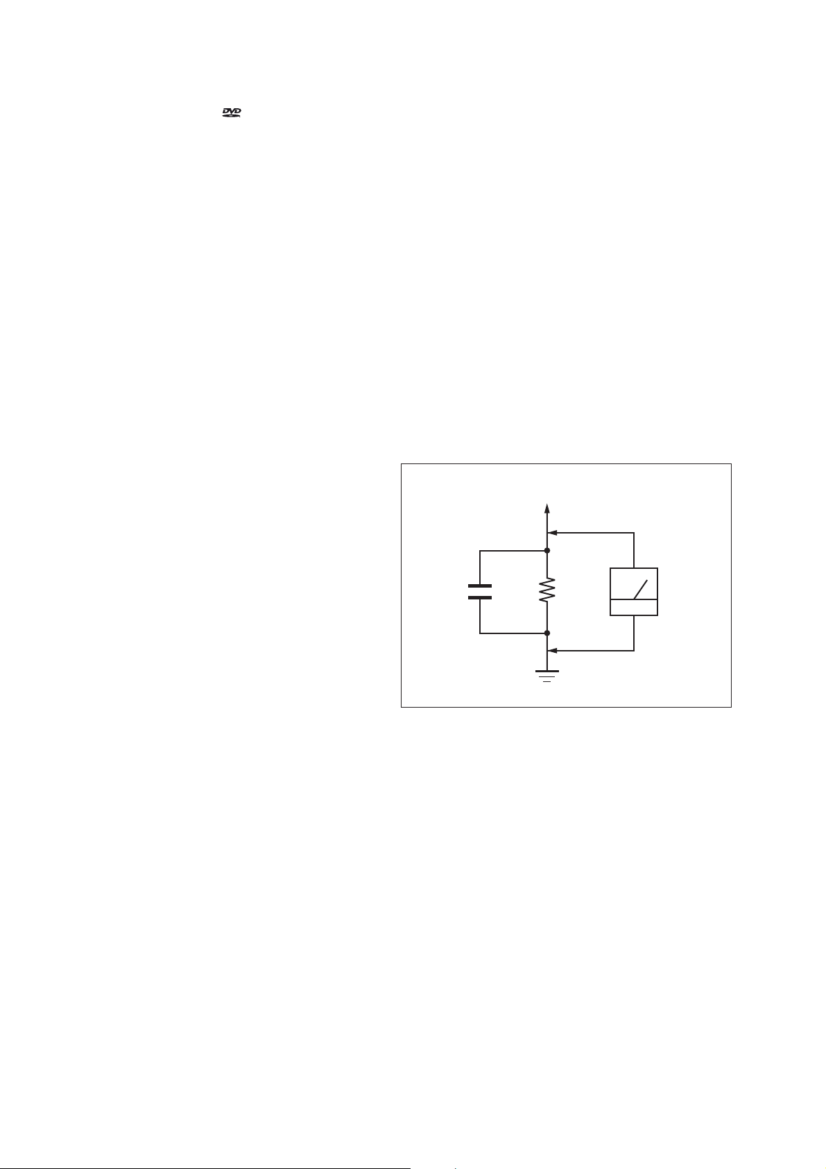
VOM or battery-operated AC voltmeter . The “limit” indication
is 0.75 V, so analog meters must have an accurate low-voltage
scale. The Simpson 250 and Sanwa SH-63Trd are examples
of a passive VOM that is suitable. Nearly all battery operated
digital multimeters that have a 2V AC range are suitable. (See
Fig. A)
To Exposed Metal
Parts on Set
AC
1.5 kΩ0.15 μF
voltmeter
(0.75 V)
Earth Ground
Fig. A. Using an AC voltmeter to check AC leakage.
SAFETY-RELATED COMPONENT WARNING!
COMPONENTS IDENTIFIED BY MARK 0 OR DOTTED LINE
WITH MARK 0 ON THE SCHEMATIC DIAGRAMS AND IN
THE PARTS LIST ARE CRITICAL TO SAFE OPERATION.
REPLACE THESE COMPONENTS WITH SONY PARTS
WHOSE PART NUMBERS APPEAR AS SHOWN IN THIS
MANUAL OR IN SUPPLEMENTS PUBLISHED BY SONY.
ATTENTION AU COMPOSANT AYANT RAPPORT
À LA SÉCURITÉ!
LES COMPOSANTS IDENTIFIÉS PAR UNE MARQUE 0 SUR
LES DIAGRAMMES SCHÉMATIQUES ET LA LISTE DES
PIÈCES SONT CRITIQUES POUR LA SÉCURITÉ DE FONCTIONNEMENT. NE REMPLACER CES COMPOSANTS QUE
PAR DES PIÈCES SONY DONT LES NUMÉROS SONT DONNÉS DANS CE MANUEL OU DANS LES SUPPLÉMENTS
PUBLIÉS PAR SONY.
2

HCD-SHAKE33/SHAKE44/SHAKE55/SHAKE66/SHAKE77/SHAKE88
Ver. 1.2
TABLE OF CONTENTS
1. SERVICING NOTES ............................................. 4
2. DISASSEMBLY
2-1. Overall Case .................................................................... 10
2-2. Back Panel Section ......................................................... 11
2-3. Loading Panel Assy ........................................................ 11
2-4. CDM90-DVBU202//M ................................................... 12
2-5. Front Panel Section ......................................................... 13
2-6. MOTHERBOARD Board ............................................... 13
2-7. 4CH DAMP Board (SHAKE33/SHAKE44),
6CH DAMP Board
2-8. REGULATOR, SWITCHING (3H401W)
(SHAKE33/SHAKE44), REGULATOR, SWITCHING
(SSNBPR) (SHAKE55/SHAKE66), REGULATOR,
SWITCHING (SSNGBR) (SHAKE77/SHAKE88) ....... 15
2-9. Service Optical Device, Wire (Flat Type) ....................... 16
(EXCEPT SHAKE33/SHAKE44)
.... 14
3. TEST MODE ............................................................ 17
4. ELECTRICAL CHECK ......................................... 22
5. TROUBLESHOOTING .......................................... 23
6. DIAGRAMS
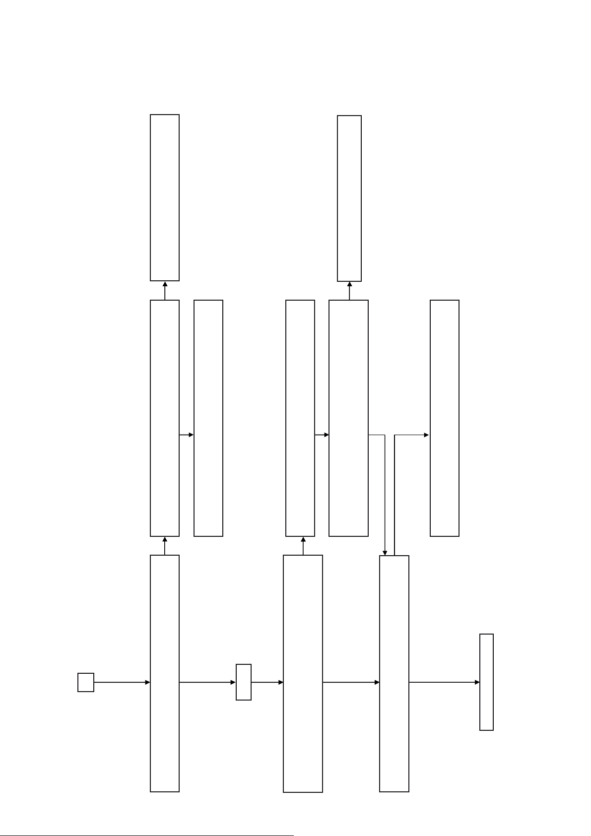
6-1. Block Diagram - RS SERVO, USB Section - ................. 31
6-2. Block Diagram - MAIN Section - ................................... 32
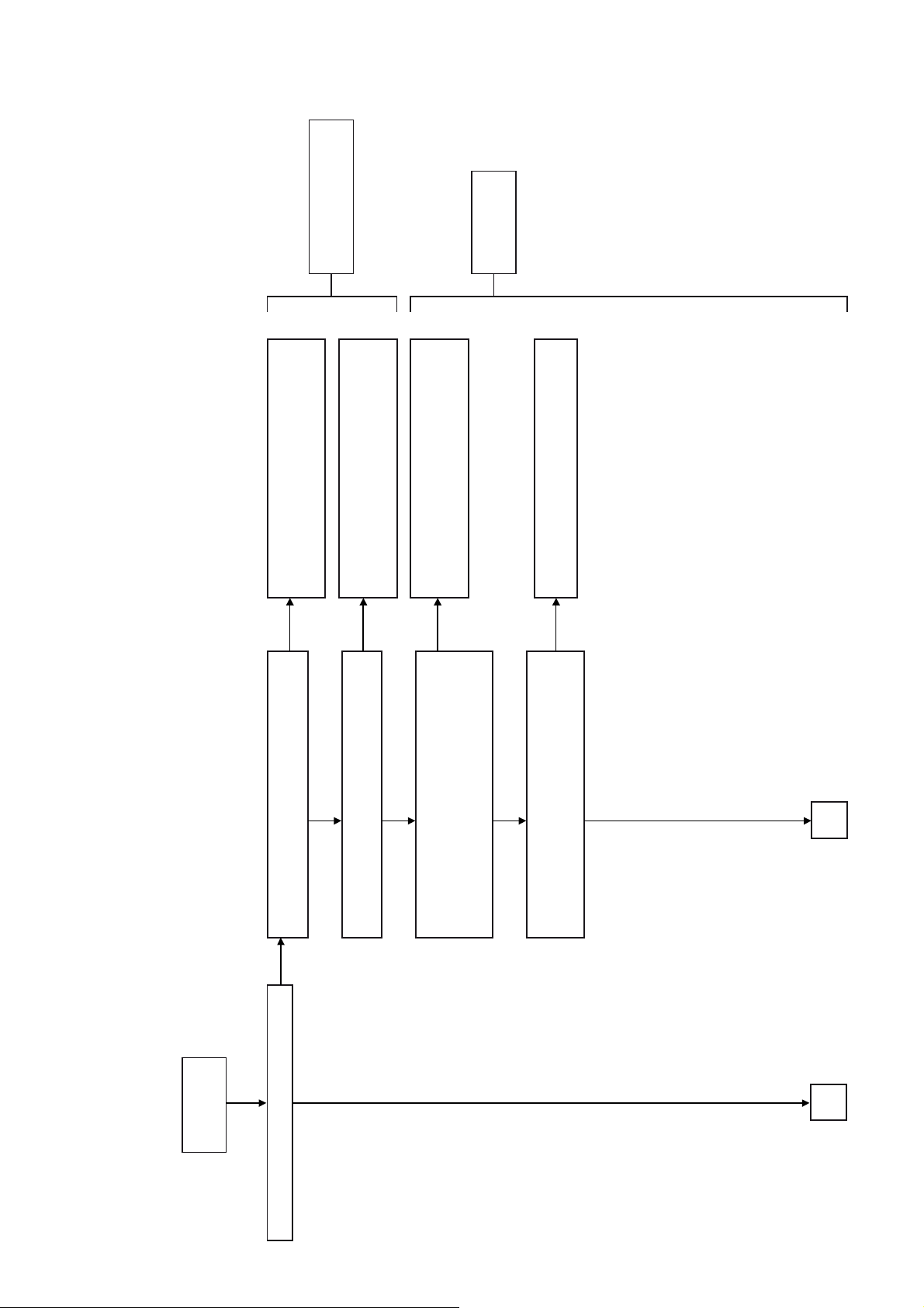
6-3. Block Diagram
- AMP Section (SHAKE33/SHAKE44) - ....................... 33
6-4. Block Diagram
- AMP Section (EXCEPT SHAKE33/SHAKE44) - ....... 34
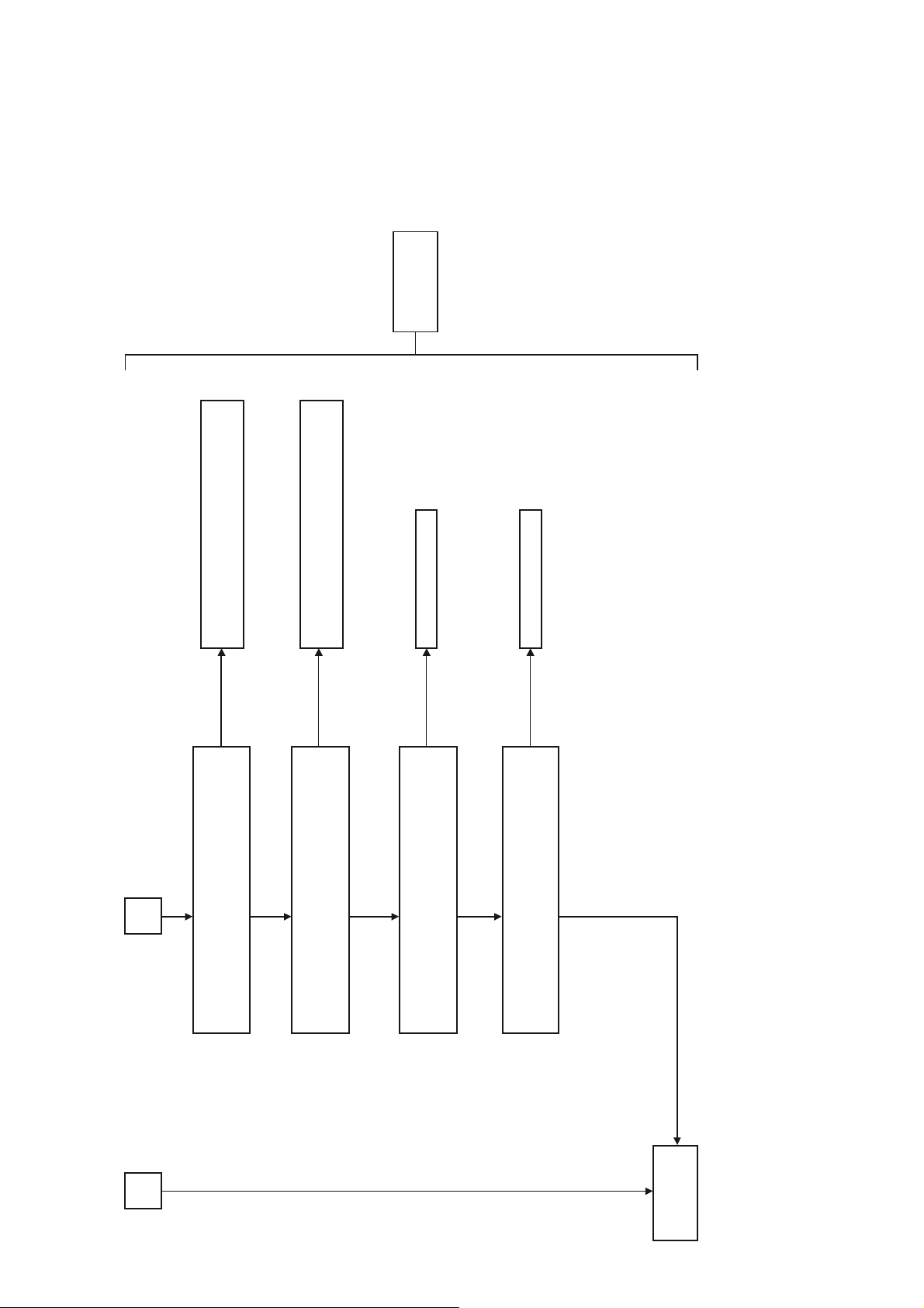
6-5. Block Diagram
- PANEL, POWER SUPPLY Section - ........................... 35
6-6. Printed Wiring Board
- MOTHERBOARD Board (Component Side) - ............ 37
6-7. Printed Wiring Board
- MOTHERBOARD Board (Conductor Side) - ............. 38
6-8. Schematic Diagram
- MOTHERBOARD Board (1/8) - ................................. 39
6-9. Schematic Diagram
- MOTHERBOARD Board (2/8) - ................................. 40
6-10. Schematic Diagram
- MOTHERBOARD Board (3/8) - ................................. 41
6-11. Schematic Diagram
- MOTHERBOARD Board (4/8) - ................................. 42
6-12. Schematic Diagram
- MOTHERBOARD Board (5/8) - ................................. 43
6-13. Schematic Diagram
- MOTHERBOARD Board (6/8) - ................................. 44
6-14. Schematic Diagram
- MOTHERBOARD Board (7/8) - ................................. 45
6-15. Schematic Diagram
- MOTHERBOARD Board (8/8) - ................................. 46
6-16. Printed Wiring Board
- 4CH DAMP Board (SHAKE33/SHAKE44) - .............. 47
6-17. Schematic Diagram
- 4CH DAMP Board (SHAKE33/SHAKE44) (1/2) - ..... 48
6-18. Schematic Diagram
- 4CH DAMP Board (SHAKE33/SHAKE44) (2/2) - ..... 49
6-19. Printed Wiring Board
- 6CH DAMP Board (EXCEPT SHAKE33/SHAKE44)
(Component Side) - ......................................................... 50
6-20. Printed Wiring Board
- 6CH DAMP Board (EXCEPT SHAKE33/SHAKE44)
(Conductor Side) - .......................................................... 51
6-21. Schematic Diagram - 6CH DAMP Board
(EXCEPT SHAKE33/SHAKE44) (1/3) - ....................... 52
6-22. Schematic Diagram - 6CH DAMP Board
(EXCEPT SHAKE33/SHAKE44) (2/3) - ....................... 53
6-23. Schematic Diagram - 6CH DAMP Board
(EXCEPT SHAKE33/SHAKE44) (3/3) - ....................... 54
6-24. Printed Wiring Board
-
STR Board (SHAKE33/SHAKE44) - .......................... 55
6-25. Schematic Diagram
-
STR Board (SHAKE33/SHAKE44) - .......................... 56
6-26. Printed Wiring Board
-
STR Board (EXCEPT SHAKE33/SHAKE44)
(Component Side) - ......................................................... 57
6-27. Printed Wiring Board
-
STR Board (EXCEPT SHAKE33/SHAKE44)
(Conductor Side) - .......................................................... 58
6-28. Schematic Diagram
-
STR Board (EXCEPT SHAKE33/SHAKE44) - .......... 59
6-29. Printed Wiring Board
-
FL Board (SHAKE33/SHAKE44) - ............................. 60
6-30. Schematic Diagram
-
FL Board (SHAKE33/SHAKE44) - ............................. 61
6-31. Printed Wiring Board
-
FL Board (EXCEPT SHAKE33/SHAKE44)
(Component Side) - ......................................................... 62
6-32. Printed Wiring Board
-
FL Board (EXCEPT SHAKE33/SHAKE44)
(Conductor Side) - .......................................................... 63
6-33. Schematic Diagram
-
FL Board (EXCEPT SHAKE33/SHAKE44) - ............. 64
6-34. Printed Wiring Board
-
MIC Board (SHAKE33/SHAKE44) - .......................... 65
6-35. Schematic Diagram
-
MIC Board (SHAKE33/SHAKE44) - .......................... 66
6-36. Printed Wiring Board
-
MIC Board (EXCEPT SHAKE33/SHAKE44) - .......... 67
6-37. Schematic Diagram
-
MIC Board (EXCEPT SHAKE33/SHAKE44) - .......... 68
6-38. Printed Wiring Board 6-39. Schematic Diagram 6-40. Printed Wiring Board -
(SHAKE44/SHAKE66/SHAKE88) - ............................. 71
6-41. Schematic Diagram -
(SHAKE44/SHAKE66/SHAKE88) - ............................. 71
TUNER Board - ........................ 69
TUNER Board - ........................... 70
VIDEO Board
VIDEO Board
7. EXPLODED VIEWS
7-1. Overall Case Section ....................................................... 88
7-2. Back Panel Section ......................................................... 89
7-3. FL Board, STR Board ..................................................... 90
7-4. Front Panel Section ......................................................... 91
7-5. MOTHERBOARD Board Section .................................. 92
7-6. Chassis Section ............................................................... 93
7-7. CD Mechanism Section (CDM90-DVBU202//M) ......... 94
8. ELECTRICAL PARTS LIST .............................. 95
3
HCD-SHAKE33/SHAKE44/SHAKE55/SHAKE66/SHAKE77/SHAKE88
Ver. 1.4
SECTION 1
SERVICING NOTES
Notes on chip component replacement
• Never reuse a disconnected chip component.
• Notice that the minus side of a tantalum capacitor may be
damaged by heat.
Flexible Circuit Board Repairing
• Keep the temperature of the soldering iron around 270 °C
during repairing.
• Do not touch the soldering iron on the same conductor of the
circuit board (within 3 times).
• Be careful not to apply force on the conductor when soldering
or unsoldering.
UNLEADED SOLDER
Boards requiring use of unleaded solder are printed with the
leadfree mark (LF) indicating the solder contains no lead.
(Caution: Some printed circuit boards may not come printed with
the lead free mark due to their particular size)
: LEAD FREE MARK
Unleaded solder has the following characteristics.
• Unleaded solder melts at a temperature about 40 °C higher
than ordinary solder.
Ordinary soldering irons can be used but the iron tip has to be
applied to the solder joint for a slightly longer time.
Soldering irons using a temperature regulator should be set to
about 350 °C.
Caution: The printed pattern (copper foil) may peel away if
the heated tip is applied for too long, so be careful!
• Strong viscosity
Unleaded solder is more viscous (sticky, less prone to fl ow)
than ordinary solder so use caution not to let solder bridges
occur such as on IC pins, etc.
• Usable with ordinary solder
It is best to use only unleaded solder but unleaded solder may
also be added to ordinary solder.
CAUTION
Use of controls or adjustments or performance of procedures
other than those specifi ed herein may result in hazardous radiation
exposure.
NOTES ON HANDLING THE OPTICAL PICK-UP BLOCK
OR BASE UNIT
The laser diode in the optical pick-up block may suffer electrostatic
break-down because of the potential difference generated by the
charged electrostatic load, etc. on clothing and the human body.
During repair, pay attention to electrostatic break-down and also
use the procedure in the printed matter which is included in the
repair parts.
The fl exible board is easily damaged and should be handled with
care.
NOTES ON LASER DIODE EMISSION CHECK
The laser beam on this model is concentrated so as to be focused
on the disc refl ective surface by the objective lens in the optical
pickup block. Therefore, when checking the laser diode emission,
observe from more than 30 cm away from the objective lens.
MODEL IDENTIFICATION
- BACK PANEL -
PART No.
Model Part No.
HCD-SHAKE77 : E2, E51, AR, AUS
HCD-SHAKE77 : MX
HCD-SHAKE88: SAF, EA, MY, E4
HCD-SHAKE88: TH
HCD-SHAKE33 : E2, E51, AR
HCD-SHAKE33 : US
HCD-SHAKE33 : MX
HCD-SHAKE33 : AEP, UK
HCD-SHAKE44: SAF, EA, MY, E4
HCD-SHAKE44: TH
HCD-SHAKE55: E2, E51, AR
HCD-SHAKE55: US
HCD-SHAKE55: MX
HCD-SHAKE66: E12, RU, MY
• Abbreviation
AR : Argentina model
AUS : Australian model
E2 : 120 V AC area in E model
E4 : African model
E12 : 220-240 V AC area in E model
E51 : Chilean and Peruvian model
EA : Saudi Arabia model
MX : Mexican model
MY : Malaysia model
RU : Russian model
SAF : South African model
TH : Thai model
4-479-323-0[]
4-479-323-2[]
4-479-323-3[]
4-479-323-4[]
4-479-422-0[]
4-479-422-1[]
4-479-422-2[]
4-479-422-3[]
4-479-422-4[]
4-479-422-5[]
4-529-223-0[]
4-529-223-1[]
4-529-223-2[]
4-529-223-4[]
PLAYABLE DISCS
• AUDIO CD
• CD-R/CD-RW/DVD-R/DVD-RW
– audio data
– MP3 fi les that conforms to ISO9660 Level 1/Level 2, or
Joliet (expansion format).
Notes
• MP3 (MPEG 1 Audio Layer-3) is a standard format defi ned
by ISO (International Organization for Standardization) which
compresses audio data. MP3 fi les must be in MPEG 1 Audio
Layer-3 format.
• The system can only play back MP3 fi les that have a fi le
extension of “.mp3”.
This appliance is classifi ed as a CLASS 1 LASER product by
IEC60825-1:2007. This marking is located on the rear exterior.
4
HCD-SHAKE33/SHAKE44/SHAKE55/SHAKE66/SHAKE77/SHAKE88
Ver. 1.4
NOTE OF REPLACING THE IC001, IC002, IC105, IC106
AND IC302 (SHAKE44/SHAKE66/SHAKE88) ON THE
MOTHERBOARD BOARD
IC001, IC002, IC105, IC106 and IC302 (SHAKE44/SHAKE66/
SHAKE88) on the MOTHERBOARD board cannot exchange
with single. When these parts on the MOTHERBOARD board are
damaged, exchange the entire mounted board.
NOTE OF REPLACEMENT OF THE MS-476 BOARD
When the MS-476 board is defective, exchange the entire
LOADING COMPLETE ASSY (T).
RELEASING THE DISC TRAY LOCK
The disc tray lock function for the antitheft of an demonstration
disc in the store is equipped.
Releasing Procedure:
1. Press [
2. Press the [CD] (SHAKE33/SHAKE55/SHAKE77) / [DVD/
3. Press the [x] button and [/+] button simultaneously and
4. The message “UNLOCKED” is displayed and the disc tray is
Note: When “LOCKED” is displayed, the slot lock is not released by
\/1] button to turn the power on.
CD] (SHAKE44/SHAKE66/SHAKE88)] button to select CD/
DVD function.
hold down for around 5 seconds.
unlocked.
turning power on/off with the [\/1] button.
NOTE OF REPLACING MOTHERBOARD BOARD OR
BLUETOOTH MODULE OR RC-S801/A (WW) BOARD
When the MOTHERBOARD board or BLUETOOTH module or
RC-S801/A (WW) board are replaced, please execute the below
service mode.
Pairing this system with a
1. Press the [\/1] button to turn the power on.
2. Place the Bluetooth device within 1 meter (3 feet) from the
system.
3. Press BLUETOOTH on the unit to select Bluetooth function.
“BLUETOOTH” appears in the display panel.
4. Hold down BLUETOOTH on the unit for 2 seconds or more.
“PAIRING” fl ashes in the display panel.
5. Perform the pairing procedure on the Bluetooth device.
6. Select the model number of the unit on the display of the
Bluetooth device.
For example, select “SONY:SHAKE-88D” (or SHAKE-33/
SHAKE-44D/SHAKE-55/SHAKE-66D/SHAKE-77). If
passkey is required on the Bluetooth device, enter “0000”.
7. Perform the Bluetooth connection on the Bluetooth device.
8. When pairing is completed and the Bluetooth connection is
established, the Bluetooth device name appears in the display
panel.
9. To cancel pairing operation, hold down BLUETOOTH on the
unit for 2 seconds or more until “BLUETOOTH” appears in
the display panel.
Bluetooth
device
NOTE OF DISASSEMBLE THE CASE, OVERALL
To disassemble the CASE, OVERALL, hexagon key is required to
unscrew the SCREW, TAPPING (HEX).
hexagon key
hexagon key
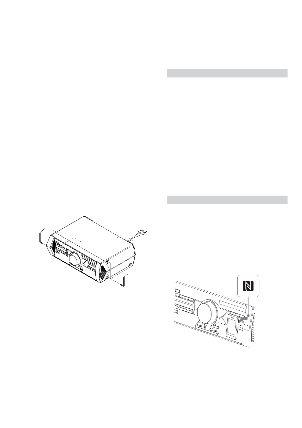
Connecting with a smartphone by one touch (NFC)
Note: The operation in this mode must use a NFC-compatible smartphone
(Smartphones with a built-in NFC function [OS: Android 2.3.3 or
later, excluding Android 3.x])
1. Press the [\/1] button to turn the power on.
2. Download and install the app “NFC Easy Connect”.
Download the free Android app from Google Play by searching
for “NFC Easy Connect”.
3. Start the app “NFC Easy Connect” on the smartphone.
Make sure that the application screen is displayed.
4. Touch the smartphone to the N-Mark on the system until the
smartphone vibrates.
Complete the connection by following the instructions
displayed on the smartphone.
5. When pairing is completed and the Bluetooth connection is
established, the Bluetooth device name appears in the display
panel.
5

HCD-SHAKE33/SHAKE44/SHAKE55/SHAKE66/SHAKE77/SHAKE88
Ver. 1.3
Playing music from a
Bluetooth
device
For a Bluetooth device
1. Press the [
\/1] button to turn the power on.
2. Press BLUETOOTH on the unit to select Bluetooth function.
“BLUETOOTH” appears in the display panel.
3. Establish connection with the Bluetooth device.
Press BLUETOOTH on the unit to connect to the last
connected Bluetooth device.
Perform the Bluetooth connection from the Bluetooth device if
the device is not connected.
Once the connection is established, the Bluetooth device name
appears in the display panel.
4. Press N.
Depending on the Bluetooth device,
– you may have to press N twice.
– you may need to start playback of an audio source on the
Bluetooth device.
For an NFC-compatible smartphone
1. Press the [\/1] button to turn the power on.
Touch the smartphone to the N-Mark on the system to establish
the Bluetooth connection.
Start playback of an audio source on the smartphone. For
details on playback, refer to the operating instructions of your
smartphone.
NOTE OF REPLACING THE COMPLETE MOTHERBOARD
BOARD (SHAKE55: US / SHAKE66: MY / SHAKE88: EA)
The COMPLETE MOTHERBOARD BOARD for this unit has
been changed in the midway of production.
When the COMPLETE MOTHERBOARD BOARD is defective,
check the label model number before repair.
Please order the related type of COMPLETE MOTHERBOARD
BOARD in part list.
R
AC 120V ~ 60Hz 500W
Contains FCC ID: PPQ-WB115C
Label Model Number
Label Model Number Type
4-487-772-1[]
4-487-772-2[]
4-529-214-1[]
4-529-214-2[]
4-529-215-2[]
4-529-215-3[]
Type A
Type B
Type C
Type D
Type E
Type F
To disconnect the Bluetooth device
For a Bluetooth device
Press BLUETOOTH on the unit.
“BLUETOOTH” appears in the display panel.
For an NFC-compatible smartphone
Touch the smartphone to the N-Mark on the system again.
To erase all the pairing registration information perform
COLD RESET test mode (Refer page 17).
6
HCD-SHAKE33/SHAKE44/SHAKE55/SHAKE66/SHAKE77/SHAKE88
y
HOW TO OPEN THE TRAY WHEN POWER SWITCH TURN OFF
Note 1: After the case overall is removed, this word is done.
Note 2: Please prepare the thin wire (clip etc. processed to the length of 8 cm or more).
1 Remove the case, overall.
(Illustration of disassembly is omitted.)
hole
– Side view –
Ver. 1.1
Insert the clip etc.
processed to the
length of 8 cm or
more in the hole
on the side of the
chassis and push.
8 cm or more
Push after it inserts it in this hole well.
Note:
CD/DVD drive
tray
2 Insert the clip etc.
– Top view –
tra
3
CAPACITOR DISCHARGE FOR ELECTRIC SHOCK PREVENTION
Switching Regulator Board (Conductor side view) (HCD-SHAKE33/SHAKE44)
In checking the Switching Regulator board, make 3 capacitors discharge of C221, C602 and C618 for eletrical shock prevention.
800 :/5 W
800 :/5 W
C618
C602
800 :/5 W
C221
7
HCD-SHAKE33/SHAKE44/SHAKE55/SHAKE66/SHAKE77/SHAKE88
Ver. 1.1
Switching Regulator Board (Conductor side view) (HCD-SHAKE55/SHAKE66/SHAKE77/SHAKE88)
In checking the Switching Regulator board, make 3 capacitors discharge of C20, C28 and C18 for eletrical shock prevention.
800 :/5 W
800 :/5 W
C20
C18
PRECAUTION WHEN INSTALLING A NEW OP UNIT/PRECAUTION BEFORE UNSOLDERING THE STATIC
ELECTRICITY PREVENTION SOLDER BRIDGE (CDM90-DVBU202//M)
C28
800 :/5 W
When installing a new OP unit, be sure to connect the fl exible printed circuit board fi rst of all before removing the static electricity
prevention solder bridge by unsoldering.
Remove the static electricity prevention solder bridge by unsoldering after the fl exible printed circuit board has already been connected.
(Do not remove nor unsolder the solder bridge as long as the OP unit is kept standalone.)
8
HCD-SHAKE33/SHAKE44/SHAKE55/SHAKE66/SHAKE77/SHAKE88
Note: Disassemble the unit in the order as shown below.
SET
2-1. OVERALL CASE
(Page 10)
2-2. BACK PANEL SECTION
(Page 11)
2-3. LOADING PANEL ASSY
(Page 11)
2-4. CDM90-DVBU202//M
(Page 12)
SECTION 2
DISASSEMBLY
Ver. 1.2
2-5. FRONT PANEL SECTION
(Page 13)
2-6. MOTHERBOARD BOARD
(Page 13)
2-7. 4CH DAMP BOARD (SHAKE33/SHAKE44),
6CH DAMP BOARD (EXCEPT SHAKE33/SHAKE44)
(Page 14)
2-8. REGULATOR, SWITCHING (3H401W) (SHAKE33/SHAKE44),
REGULATOR, SWITCHING (SSNBPR) (SHAKE55/SHAKE66),
REGULATOR, SWITCHING (SSNGBR) (SHAKE77/SHAKE88)
(Page 15)
2-9. SERVICE OPTICAL DEVICE,
WIRE (FLAT TYPE)
(Page 16)
9
HCD-SHAKE33/SHAKE44/SHAKE55/SHAKE66/SHAKE77/SHAKE88
Ver. 1.1
Note: Follow the disassembly procedure in the numerical order given.
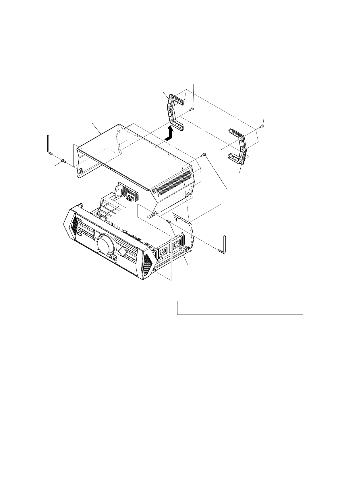
2-1. OVERALL CASE
2 two screws
3 protector, rear L
9 case, overall
8
6 three screws
(tapping (HEX))
(+BVTP 3 u 8) (BLACK)
1 four screws
(+BVTP 3 u 8) (BLACK)
4 protector, rear R
5 seven screws
(+BVTP 3 u 8) (BLACK)
7 three screws
(tapping (HEX))
Note: To disassemble the CASE, OVERALL, allen key
is required to unscrew the SCREW, T APPING (HEX).
10
HCD-SHAKE33/SHAKE44/SHAKE55/SHAKE66/SHAKE77/SHAKE88
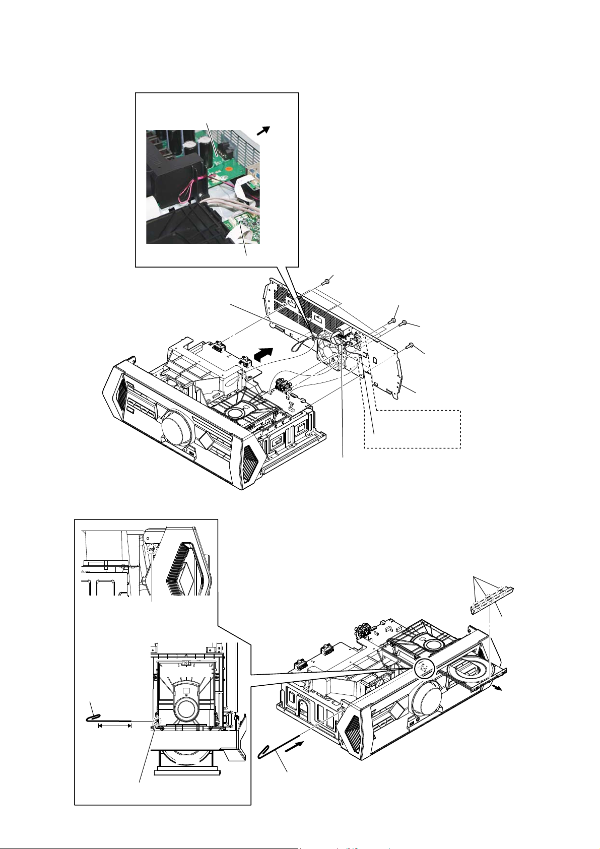
2-2. BACK PANEL SECTION
:LUHVHWWLQJ
6CH DAMP board
MOTHERBOARD board
1 CN1002 (3P)
(EXCEPT SHAKE33/SHAKE44)
CN1003 (3P)
(SHAKE33/SHAKE44)
rear side
8
Ver. 1.1
4 two screws
(+BVTP 3 u 8) (BLACK)
5 two screws
(+BVTP 3 u 8) (BLACK)
6 three screws
(+BVTP 3 u 8) (BLACK)
7 four screws
(+BVTP 3 u 8) (BLACK)
2-3. LOADING PANEL ASSY
hole
– Side view –
Insert the clip etc.
processed to the
length of 8 cm or
more in the hole
on the side of the
chassis and push.
CD/DVD drive
9 back panel section
(SHAKE44/SHAKE66/
SHAKE88)
3 CN901 (2P)
2 wire (flat type)
(9 core) (CN851)
3 three claws
4 panel, loading
assy
2
8 cm or more
tray
Push after it inserts it in this hole well.
Note:
– Top view –
1 Insert the clip etc.
11
HCD-SHAKE33/SHAKE44/SHAKE55/SHAKE66/SHAKE77/SHAKE88
Ver. 1.1
2-4. CDM90-DVBU202//M
9 CDM90-DVBU202//M
7 boss
Note: When you install the CD
drive (CDM90-DVBU202//M),
please match the position of
the boss two places.
0 two screws
(+BVTP 3 u 8)
6 four screws
(+BVTP 3 u 8)
8
:LUHVHWWLQJ
CDM90-DVBU202//M
rear side
MOTHERBOARD board
1 CN401 (6P)
3 wire (flat type) (24 core)
(CN302)
2 wire (flat type) (5 core)
(CN303)
qa two screws
(+BVTP 3 u 8)
:LUHVHWWLQJ
qs bracket, CDM (M7)
(;&(376+$.(
5 CN601 (4P)
4 CN451 (10P)
front side
12
CDM90-DVBU202//M
bracket, tunnel
HCD-SHAKE33/SHAKE44/SHAKE55/SHAKE66/SHAKE77/SHAKE88
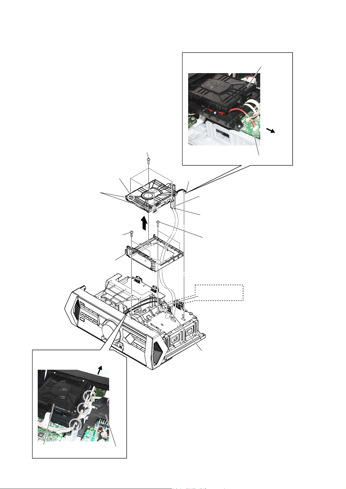
2-5. FRONT PANEL SECTION
5 one screw
(+PWH 3 u 8 (SUMITITE))
7 front panel section
Ver. 1.1
2 wire (flat type)
(23 core) (CN109)
1 wire (flat type)
(10 core) (CN102)
6
3 wire (flat type)
(8 core) (CN105)
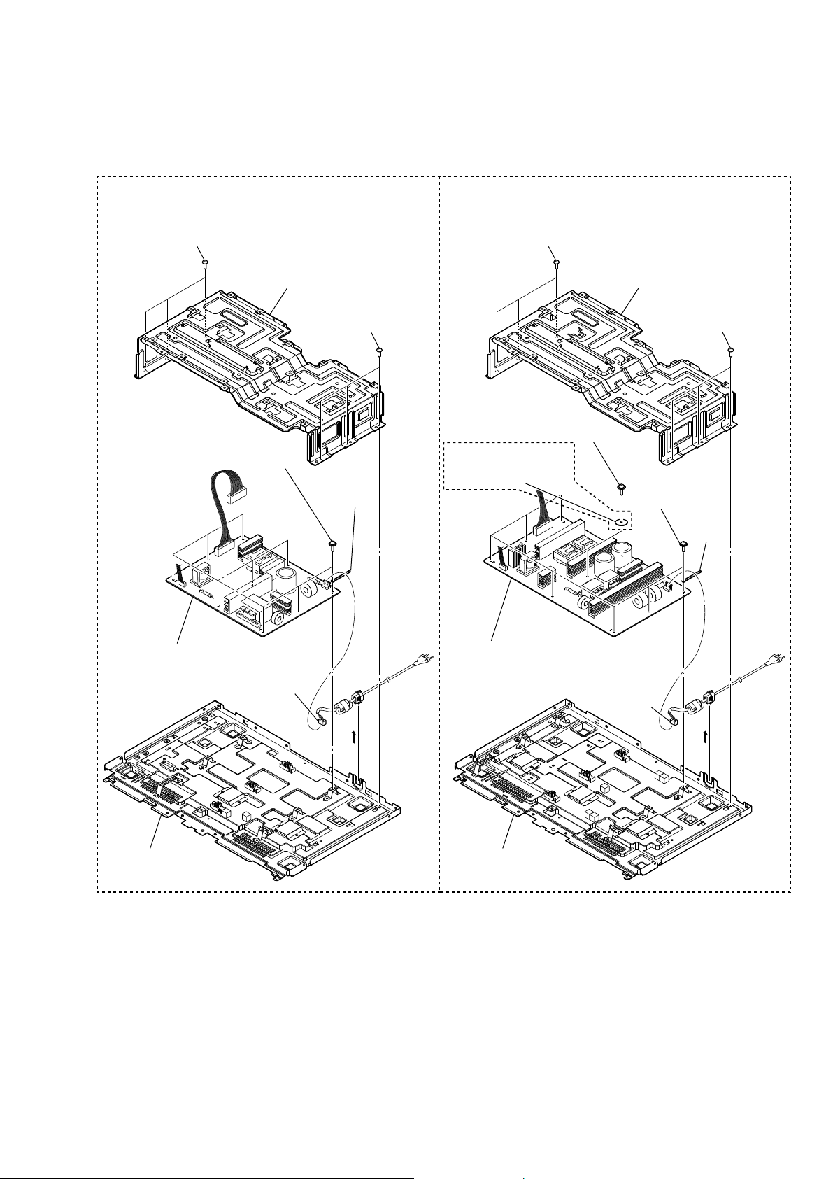
2-6. MOTHERBOARD BOARD
2 wire (flat type)
(21 core) (CN111)
4 MOTHERBOARD board
4 five screws
(+BVTP 3 u 8)
3 five screws
(+BVTP 3 u 8)
1 CN001 (6P)
13
HCD-SHAKE33/SHAKE44/SHAKE55/SHAKE66/SHAKE77/SHAKE88
Ver. 1.1
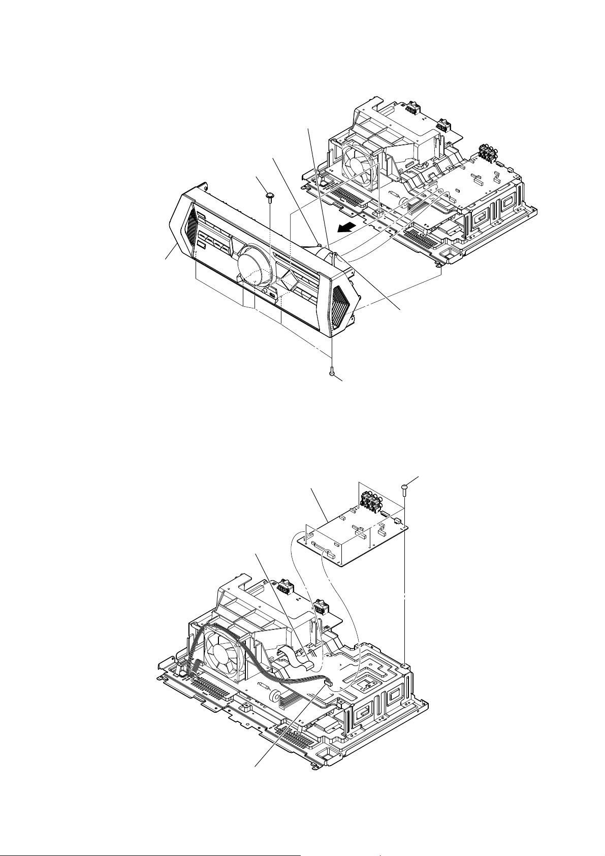
2-7. 4CH DAMP BOARD (SHAKE33/SHAKE44), 6CH DAMP BOARD (EXCEPT SHAKE33/SHAKE44)
(;&(376+$.(6+$.(6+$.(6+$.(
:LUHVHWWLQJ
front side
1 CN1001
(2P)
4 fan, DC
8 sheet,
thermal
bracket,
tunnel
(M3)
REGULATOR, SWITCHING (3H401W)
2 four screws
(+BVTP 3 u 8)
3 two screws
(+BVTP 3 u 8)
B
C
5 bracket,
tunnel (M3)
7 three screws
(+PTPWH 2.6 u L
(DIA8.0))
9 heat sink (M3)
0 four screws
(+BVTP 3 u 8)
:LUHVHWWLQJ
front side
6CH DAMP board
2 two screws
(+BVTP 3 u 8)
4 DC fan
1 CN1001 (2P)
8 thermal sheet
C
bracket, tunnel
(M7)
3 two screws
(+BVTP 3 u 8)
2 two screws
(+BVTP 3 u 8)
5 bracket,
B
tunnel (M7)
7 three screws
(+PTPWH 2.6 u L (DIA8.0))
9 heat sink (M5)
(SHAKE55/SHAKE66)
heat sink
(SHAKE77/SHAKE88)
0 six screws
(+BVTP 3 u 8)
qa 4CH DAMP
board
14
qs
E
D
qd bracket,
heat sink
qa 6CH DAMP board
6 CN1000 (10P)
C
qs
E
D
qd bracket, heat sink (M7)
B
D
HCD-SHAKE33/SHAKE44/SHAKE55/SHAKE66/SHAKE77/SHAKE88
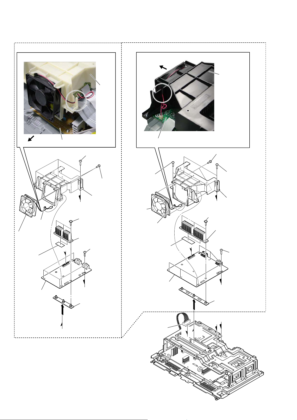
2-8. REGULATOR, SWITCHING (3H401W) (SHAKE33/ SHAKE44), REGULATOR, SWITCHING (SSNBPR) (SHAKE55/SHAKE66), REGULATOR, SWITCHING (SSNGBR) (SHAKE77/SHAKE88)
Ver. 1.4
(SHAKE33/SHAKE44)
1 three screws
(+BV3 (3-CR))
5 nine screws
(+PWH 3 u 8 (SUMITITE))
2 chassis, sub (M7)
1 three screws
(+BV3 (3-CR))
6 stopper,
wiring
(EXCEPT SHAKE33/SHAKE44)
1 three screws
(+BV3 (3-CR))
5 two screws
(+PWH 3 u 8 (SUMITITE))
(SHAKE77/SHAKE88)
6 two washer,
dia 20.0mm
2 chassis, sub (M7)
1 three screws
(+BV3 (3-CR))
5 seven screws
(+PWH 3 u 8
(SUMITITE))
7 stopper,
wiring
7 REGULATOR, SWITCHING
(3H401W)
3 CN1 (2P)
8 chassis assy (M3)
4
8 REGULATOR, SWITCHING (SSNBPR)
(SHAKE55/SHAKE66)
REGULATOR, SWITCHING (SSNGBR)
(SHAKE77/SHAKE88)
3 CN1 (2P)
4
9 chassis assy (M7)
15
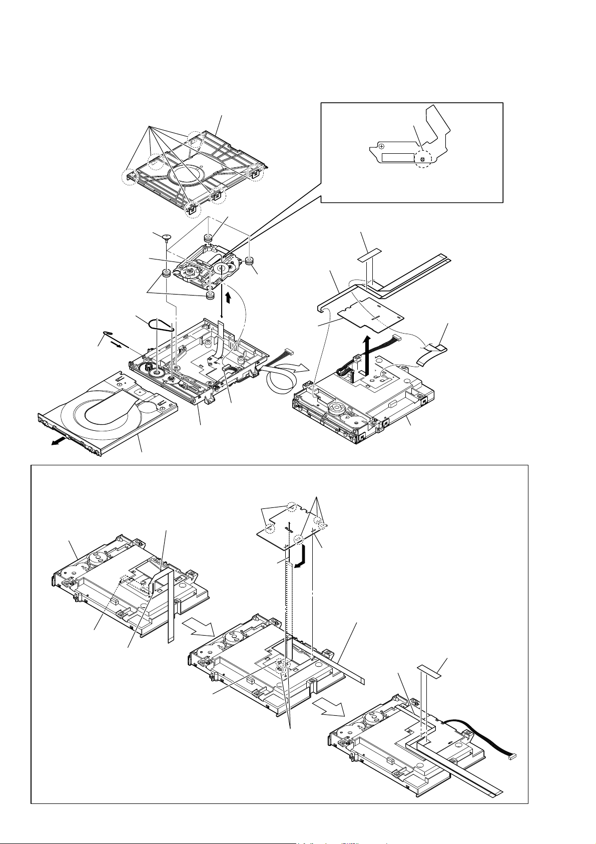
HCD-SHAKE33/SHAKE44/SHAKE55/SHAKE66/SHAKE77/SHAKE88
Ver. 1.1
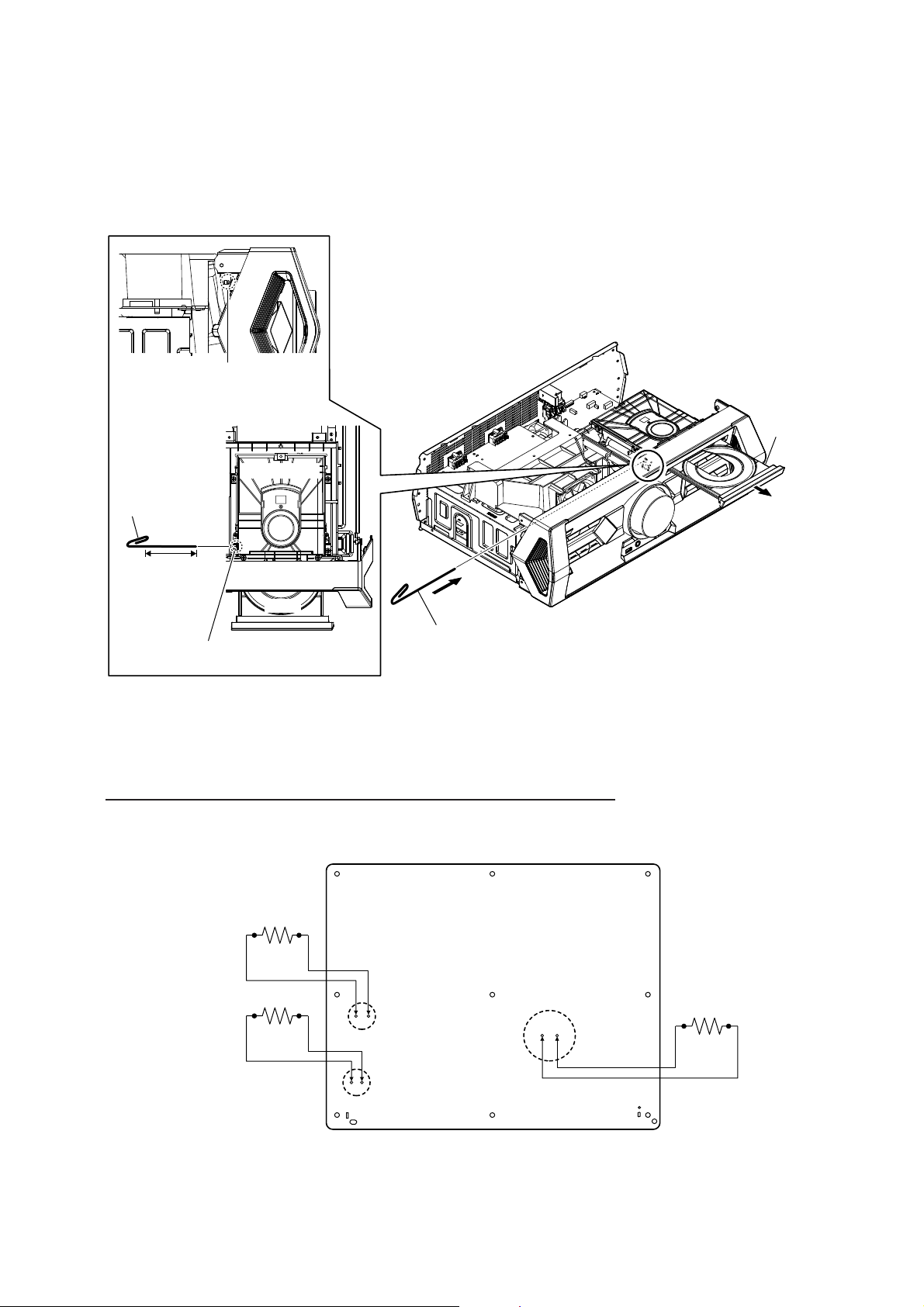
2-9. SERVICE OPTICAL DEVICE, WIRE (FLAT TYPE)
Note 1 : Before disconnecting the wire (fl at type) (24 core) of optical pick-up block, solder the short-land.
2 chuck holder assy (T)
1 six claws
qa insulator
8 four insulator screws
2 Solder the short-land.
Note 2: When assembling the service optical device,
remove the solder of short-land after
connecting the wire (flat type) (24 core).
qg tape
qs service,
optical device
qa insulator
qa insulator
6 belt
3 Insert the thin
wire (clip etc.).
qd base, lo assy
4
5 tray
,QVWDOODWLRQRIZLUHIODWW\SHFRUHDQGZLUHIODWW\SHFRUH
This illustration sees the loading assy (T) from bottom side.
Note:
1 wire (flat type) (24 core)
loading assy (T)
0
9
qj holder, FFC
7 connector
5 two claws
qf wire (flat type)
(5 core)
qk wire (flat type)
(24 core)
qh
loading assy (T)
– Bottom view –
5 three claws
16
terminal face
2 Through the hole
Under the guide
(Fold area)
3 Through the hole
Under the guide
6 holder, FFC
4
7 wire (flat type)
(24 core)
8 wire (flat type)
(5 core)
9 tape

HCD-SHAKE33/SHAKE44/SHAKE55/SHAKE66/SHAKE77/SHAKE88
SECTION 3
Ver. 1.1
TEST MODE
[PANEL TEST MODE]
This mode is used to check the fl uorescent indicator tube, LEDs,
keys, [VOLUME/DJ CONTROL] jog, model, destination and
software version.
Procedure:
1. Press [OPTIONS]
simultaneously and hold 3 seconds.
2. All LEDs and segments in fl uorescent indicator tube are lighted
up. All RGB LEDs are lighted up in white color.
3. When you want to enter to the software version display mode,
press [+]*1 / [PRESET + +]*2 button.
The model information appears on the fl uorescent indicator
tube.
Press [+]*1 / [PRESET + +]*2 button again to view the
destination information.
4. During the destination information display, press [+]*1 /
[PRESET + +]*2 button. Each time [+]*1 / [PRESET +
+]*2 button is pressed, the fl uorescent indicator tube
shows the version of each category software in the following
sequence: SC, MTK, OPU, UI, PF , SYS, CD, CDMA, CDMB,
ST, TA, TM and return back to model information display.
5. When [] button is pressed while the version numbers are
being displayed except model and destination, the date of the
software creation appears. When [] button is pressed again,
the display returns to the software version display.
6. Press [‒]*1 / [‒ PRESET ‒]*2 button, the key check mode
is activated.
7. In the key check mode, the fluorescent indicator tube displays
“K 0 V0”.
Each time a button is pressed, “K” value increases. However,
once a button has been pressed, it is no longer taken into
account.
“V” value increases in the manner of 0, 1, 2, 3 ... if
[VOLUME/DJ CONTROL] knob is turned clockwise, or
it decreases in the manner of 0, 9, 8, 7 ... if [VOLUME/DJ
CONTROL] knob is turned counterclockwise.
8. When [ENTER] button is pressed after all LEDs and segments
in fl uorescent indicator tube light up, alternate segments in
fl uorescent indicator tube and LEDs would light up, all RGB
LEDs would light up in red color. If you press [ENTER]
button again, another half of alternate segments in fl uorescent
indicator tube and LEDs would light up, all RGB LEDs
would light up in green color. Pressing [ENTER] button again
would cause all segments in fl uorescent indicator tube and
LEDs light up, all RGB LEDs would light up in blue color.
Pressing [ENTER] button again would turn off all segments in
fl uorescent indicator tube and all LEDs including RGB LEDs.
9. To release from this mode, press the buttons in the same
manner as step 1, or disconnect the power cord.
*1
/ [X]*2 button and [FOOTBALL] button
[COLD RESET]
The cold reset clears all data including preset data stored in the
data fl ash to initial conditions included history mode data. Execute
this mode when returning the set to the customer.
Procedure:
1. Press [
2. Press [] button and [OPTIONS]*1 / [X]*2 button simultane-
3. “COLD RESET” appears on the fl uorescent indicator tube.
[CD TRAY LOCK MODE]
This mode let you lock the disc tray. When this mode is activated,
the disc tray will not open when [ZOPEN/CLOSE] button is
pressed. The message “LOCKED” will be displayed on the
fl uorescent indicator tube. This mode only applied when there is
disc(s) on the tray.
Procedure:
1. Press [\/1] button to turn on the system.
2. Select DVD/CD function.
3. Press [] button and [+]*1 / [PRESET + +]*2
\/1] button to turn on the system.
ously for 3 seconds.
After that, the fl uorescent indicator tube becomes blank for a
while, and the system is reset.
button simultaneously and hold down until “LOCKED” or
“UNLOCKED” displayed on the fl uorescent indicator tube
(around 5 seconds).
[USER RESET]
The user reset clears all data including preset data stored in the data
fl ash to initial conditions exclude history mode data.
Procedure:
1. Press [\/1] button to turn on the system.
2. Press [] button and [LED COLOR] button simultaneously
for 3 seconds.
3. “RESET” appears on the fl uorescent indicator tube. After that,
the fl uorescent indicator tube becomes blank for a while, and
the system is reset.
Note: *1 SHAKE33/SHAKE55/SHAKE77 models
*2
SHAKE44/SHAKE66/SHAKE88 models
17
HCD-SHAKE33/SHAKE44/SHAKE55/SHAKE66/SHAKE77/SHAKE88
Ver. 1.1
[HISTORY MODE]
This mode is used to check important data stored in the system
when PROTECTOR happen.
Procedure:
1. During demo mode, press [OPTIONS]
[FLANGER] button for 5 seconds to mode into history mode.
Press the [TUNING + M > ]*1 / [
2.
button
or [TUNING ‒ . m]*1 / [
button to check history data stored.
Display on fl uorescent indicator tube Description
PROCOUNT
PROTYPE
T1
T2
FUNC
※※※※※H※※
※※※※※H※※
※※※※※※※
VOL
ATT
EQ LOW
EQ MI D
EQ HIGH
SURR
DJ
※※※※※※ ※※
BAZUCA
*1
/ [X]*2 button and
TUNING + >]*2
TUNING ‒ .]*2
※※
※※※※
M
M
※※※
※※※
※※※
※※※
※※※
※※※
※※※
No of time protector happen (0 ~ 99)
Refer to protect type description
Single Power On Time until protector happened
(0~99999 hours, 0~99Min)
Total Power On Time [ no consider protector happen ]
(0~99999 hours, 0~99Min)
Input Function during protector happened
Volume setting (MIN / 1 - 50 / MAX)
Actual attenuation (-87 … 0)
Low EQ level (-6 … 0 … +6)
Mid EQ level (-6 … 0 … +6)
High EQ level (-6 … 0 … +6)
Surround setting (OFF / ON)
DJ Effect setting
DJ Mode: OFF/ISOLAT/FLANGE/PAN/WAH
DJ Setting Value: 1~ 40
Bass Bazuca setting (OFF / ON)
To release from History Mode.
To release from this mode, press [
\/1] button.
Protect T ype Description:
Error Code Description
E01 The over current condition to MOSFET occurs
by defect of MOSFET or defect of PS output
line.
E03 Defect of power supply circuit to AMP.
There is possibility of unusual power supply of
any of the AMP IC or Pre-amplifi er.
E04 DC appears in SP terminal by defect of AMP
IC and MOSFET
or
Defect of DC FAN and DC FAN driver circuit
E05 Unusual heat up of MOSFET by improper
assembly of heat sink, destruction of MOSFET
etc.
If speaker does not have output even if the set status is not in
PROTECT mode, the following defect might be possible:
Defects Possible cause
RESET defect Reset signal status from micom is not ‘H’.
18
Note: *1 SHAKE33/SHAKE55/SHAKE77 models
*2
SHAKE44/SHAKE66/SHAKE88 models
HCD-SHAKE33/SHAKE44/SHAKE55/SHAKE66/SHAKE77/SHAKE88
Ver. 1.1
[MODEL & DEST WRITE MODE]
This mode is used to set software model & destination.
This mode only available when no permanent model & destination
is stored.
Procedure:
1. Press [MOVIE/GAME] button & [LED PATTERN] button
simultaneously and hold for 5 seconds.
2. Fluorescent indicator tube display will show “M XXXXX”.
3. Press [+]
*1
/ [PRESET + +]*2 / [‒]*1 / [‒ PRESET ‒]
*2
button to select the model based on the set’s model.
Product Code F. Tube display
SHAKE-33 “M MAGMA3”
SHAKE-55 “M MAGMA5”
SHAKE-77 “M MAGMA7”
SHAKE-44D “M MAGMA3D”
SHAKE-66D “M MAGMA5D”
SHAKE-88D “M MAGMA7D”
4. Press [ENTER] button.
5. Fluorescent indicator tube display will show “D XXXXX”.
6. Press [+]
*1
/ [PRESET + +]*2 / [‒]*1 / [‒ PRESET ‒]
*2
button to select the destination based on the set’s country.
Area Code Country F. Tube display
J1 Japan “D J”
JE1 Tourist “D JE”
U2/CA2 America, Canada “D NA”
CEL/CE1/
Europe(general) “D CE2”
CE2
CEK U.K. “D CEK”
RU1/RU3 Russia “D RU”
AU1 Australia “D AU”
CN1 China “D CN”
E12 India, Pakistan, Morocco “D E12”
E3/E15 Middle East, Iran “D E3”
E4/EA3/
Saudi Arabia, Africa “D EA3”
E93/SA2
HK1/
HK2/PL1/
SP1/SP2/
Hong Kong, Philippines,
Singapore, Malaysia,
Thailand
“D ASIA”
SP6/TH1
KR2 Korea “D KR”
TW2 Taiwan “D TW”
E2, E32,
E51, AR2
Latin America(general),
Chile, Peru, Argentina
“D LATIN”
BR1 Brazil “D BR”
MX2,
Mexico “D MX”
MX4
7. Press [ENTER] button to confi rm the selection.
8. “RESET” appears on the fl uorescent indicator tube. After that,
the fl uorescent indicator tube becomes blank for a while, and
the system is reset.
9. Mode in [PANEL TEST MODE] again to confi rm on the
model & destination.
[DVD COLOR SYSTEM MODE]
• This mode let you change the color system of the video output
from PAL to NTSC or vice-versa.
Procedure:
1. Press the [\/1] button to turn on the system.
2. Press the [DVD/CD] button.
3. Press the [DVD/CD] button and [PAN] button simultaneously
and hold for 3 seconds.
4. The message “COLOR PAL” or “COLOR NTSC” appears on
the fl uorescent indicator tube.
• To release from DVD Color System Mode
1. Once t he color system has b een selected , the mode is fi xe d
there after. If you wish to change the mode again, perform the
above item 2 again.
[DVD SERVICE MODE]
• This mod e let you make diag nosis and a djustme nt easily by
using the r emote comma nder and the T V. T he instr uctions ,
diagnostic results, etc. are given on the on-screen display.
• TEST DISC LIST
Be sure to use the DVD disc that matches the signal standards
of your region.
• CD
YEDS-18 (Part No.: 3-702-101-01)
PATD-012 (Part No.: 4-225-203-01)
• DVD SL (Single Layer)
NTSC : HLX-503 (Part No.: J-6090-069-A)
HLX-504 (Part No.: J-6090-088-A)
PAL : HLX-506 (Part No.: J-6090-077-A)
• DVD DL (Double Layer)
NTSC :
HLX-505
HLX-501 (Part No.: J-6090-071-A)
(Part No.: J-6090-089-A)
PAL : HLX-507 (Part No.: J-6090-078-A)
• Procedure to enter to DVD Service Mode:
1. Press the [\/1] button to turn on the system.
2. Press the [DVD/CD] button.
3. Press the [DVD/CD] button and [W AH] button simultaneously
and hold 3 seconds.
4. The message “SERVICE IN” appears on the fl uoresc ent
indicator tube.
The display of the “Model Name” of the “Remocon Diagnosis
Menu” change with the model and the de stinat ion appears on
screen display. Refer to below on the model name.
HCD-SHAKE44: MAGMA3D
HCD-SHAKE66: MAGMA5D
HCD-SHAKE88: MAGMA7D
Remocon Diagnosis Menu
0. External Chip Check
1. Servo Parameter Check
2. Drive Manual Operation
3. Emergency History
4. Version Information
5. USB Test Mode Setting
Model Name
IF-con
Syscon
: GSX8D_ XX
: Ver. XX.XX (XXXX)
: Ver. X.XXX
*1
*1: Changes depending on destination
5. To execute each fu nct ion , pre ss it s number by usi ng nu me r ic
button on the remote commander.
6. To release from t his mode, pres s t h e [ \/1] button to turn off
the system.
Note: *1 SHAKE33/SHAKE55/SHAKE77 models
*2
SHAKE44/SHAKE66/SHAKE88 models
19
HCD-SHAKE33/SHAKE44/SHAKE55/SHAKE66/SHAKE77/SHAKE88
Ver. 1.1
• Execute IOP Measurement
In or der to execute IOP measurement, the following standard
procedures must be followed.
1. From the Top Menu of Remocon Diagnosis Menu, select
“2. Dr ive Manual Oper ation” by pressing t he [2] button on
the remote commande r. The following sc re en ap pea r s on the
onscreen display.
Drive Manual Operation
1. Servo Control
2. Track/Layer Jump
3. Manual Adjustment
4. Mecha test mode
5. MIRR time Adjust
0. Return to Top Menu
2. Select “3. Manu al Adjust me nt ” by pre ssi ng th e [3] button on
the remote commande r. The following sc re en ap pea r s on the
on-screen display.
Manual Adjust
1. Track Balance Adjust:
2. Track Gain Adjust:
3. Focus Balance Adjust:
4. Focus Gain Adjust:
5. Eg Boost Adjust:
6. Iop:
7. TRV. Level:
8. S curve (FE) Level:
9. RFL (PI) Level:
0. MIRR Time:
• Check Emergency History
To check the emer gency hi stor y, please follow the following
procedure.
1. From the Top Menu of Remocon Diagnosis Menu, select
“3. Emergency History” by pressing the [3] button on the
remote com mander. The following scre en a pp e a r s on t he onscreen display.
Emg. History Check
Laser Hours CD 999h 59min
1. 01 05 04 04
00 00 00 00
2. 02 02 01 01 00 A9 4B 00
00 00 00 00
Next Next Page Prev Prev Page
O Return to Top Menu
DVD 999h 59min
00 92 46 00
00 00 23 45
00 00 23 45
2. You can check the total time when the laser is turned on
duri ng playba ck of DVD and CD fr om the above menu. T he
maximum time, which can be displayed are 999h 59min.
3. You can check the e rr or code of late st 10 emergency h istor y
from the ab ove menu. To view the previou s or next page of
emergency h istory, press t he [.] button or [>] butt on
on the remote commander. The error code consists of
• Error Code
Example of Error code
O o Change Value
RETURN Return to previous menu
3. Select “6. Iop:” by pressing the [6] button on the remote
commander.
4. Wait unt il a hexadecimal numb er appears in the on -screen
display as below:
Manual Adjust
1. Track Balance Adjust:
2. Track Gain Adjust:
3. Focus Balance Adjust:
4. Focus Gain Adjust:
5. Eg Boost Adjust:
6. Iop. ED
7. TRV. Level:
8. S curve (FE) Level:
9. RFL (PI) Level:
0. MIRR Time:
O o Change Value
RETURN Return to previous menu
5. Convert data from hexadecimal to decimal by using
conversion table.
6. Please fi nd the label on the rear of the BU (Base Unit).
The default IOP value is written in the label.
7. Subtract between these two values.
8. If the remainder is smaller than 93 (decimal), then it is OK.
However if the value is higher than 93, then the BU is defective
and need to be change.
9. Press the [R ETURN] but ton on the remote comma nder to
return to previous menu.
10. Press the [0] button on the remote commander to return to the
Top Menu of Remocon Diagnosis Menu.
11. Press the [\/1] button to turn off the system.
1. 01 05 04 04 00 92 46 00
00 00 00 00 00 00 23 45
The meaning of error code is as below:
01: Communication error (No reply from syscon)
02: Syscon hung up
03: Power OFF request when syscon hung up
19: Thermal shutdown
24: MoveSledHome error
25: Mechanical move error (5 Changer)
26: Mechanical move stack error
30: DC motor adjustment error
31: DPD offset adjustment error
32: TE balance adjustment error
33: TE sensor adjustment error
34: TE loop gain adjustment error
35: FE loop gain adjustment error
36: Bad jitter after adjustment
40: Focus NG
42: Focus layer jump NG
51: Spindle stop error
52: Open kick spindle error
60: Focus on error
61: Seek fail error
62: Read Q data/ID error
70: Lead in data read fail
71: TOC read time out (CD)
80: Can’t buffering
81: Unknown media type
20
HCD-SHAKE33/SHAKE44/SHAKE55/SHAKE66/SHAKE77/SHAKE88
Ver. 1.1
• Parameter of error code
This is the detail of error code.
Example of Error code
1. 01 05 04 04 00 92 46 00
00 00 00 00 00 00 23 45
• Time of error code
This is the laser time when an error occurred.
Example of Error code
1. 01 05 04 04 00 92 46 00
00 00 00 00 00 00 23 45
To clear the Laser Hours
Press the [
DISPLAY] button and then press the [CLEAR]
button. The data for both CD and DVD data are reset.
Emg. History Check
Laser Hours CD 0h 0min
1. 01 05 04 04
00 00 00 00 00 00 23 45
2. 02 02 01 01 00 A9 4B 00
00 00 00 00 00 00 23 45
Next Next Page Prev Prev Page
O Return to Top Menu
DVD 0h 0min
00 92 46 00
To return to the Top Menu of Remocon Diagnosis Menu
Press the [0] button on the remote commander.
• Check Version Information
To check the version information, please follow the following
procedure.
1. From the Top Menu of Remocon Diagnosis Menu , select “4.
Version information” by pressing the [4] button on the remote
comma nder. The following scree n appear s on the on-scre en
display.
Version information
Firm (Main) : Ver. xxxxx
Firm (Sub) : xxxxx
RISC : xxxxx
8032 : xxxxx
Audio DSP : xxxxx
Servo DSP : xxxxx
O Return to Top Menu
To return to the Top Menu of Remocon Diagnosis Menu, press
the [0] button on the remote commander.
To clear the Emergency History
Press the [DVD TOP MENU] button and then press the [CLEAR]
button.
The error code for all emergency history would be reset.
Emg. History Check
Laser Hours CD 999h 59min
1. 00 00 00 00
00 00 00 00
2. 00 00 00 00 00 00 00 00
00 00 00 00 00 00 00 00
Next Next Page Prev Prev Page
O Return to Top Menu
DVD 999h 59min
00 00 00 00
00 00 00 00
To clear the Initialize Setup Data
Press the [DVD/TUNER MENU] button and then press the
[CLEAR] button on the remote commander.
Emg. History Check
Laser Hours CD 999h
DVD 999h 59min
Initialize setup data...
59min
Next Next Page Prev Prev Page
O Return to Top Menu
21

HCD-SHAKE33/SHAKE44/SHAKE55/SHAKE66/SHAKE77/SHAKE88
Ver. 1.1
SECTION 4
ELECTRICAL CHECK
TUNER SECTION
0 dB = 1 ȝV
FM AUTO STOP CHECK
signal
generator
set
+
75
–
Procedure:
1. Turn the power on.
2. Input the following signal from Signal Generator to FM
antenna input directly.
Carrier frequency : A = 87.5 MHz, B = 98 MHz, C = 108 MHz
Deviation : 75 kHz
Modulation : 1 kHz
ANT input : 35 dBu (EMF)
Note: Please use 75 ohm “coaxial cable” to connect SG and the
set. You cannot use video cable for checking.
Please use SG whose output impedance is 75 ohm.
FOCUS BIAS CHECK
oscilloscope
(DC range)
MOTHERBOARD board
CN302 pin 17 (RFMON)
CN302 pin 1 (GND)
+
–
Procedure:
1. Connect the oscilloscope to CN302 pin 17 (RFMON) and
CN302 pin 1 (GND) on the MOTHERBOARD board.
2. Press the [
] button to turn the power on, and press the [CD]
?/1
(SHAKE33/SHAKE55/SHAKE77) / [DVD/CD] (SHAKE44/
SHAKE66/SHAKE88) button to select CD/DVD function.
3. Set the test disc (DVD: HLX-503 (NTSC) or HLX-504 (P AL),
CD: YEDS-18) on the tray and press [u] button to playback.
4. Confi rm that oscilloscope waveform is as shown in the fi gure
below (eye pattern).
A good eye pattern means that the diamond shape () in the
center of the waveform can be clearly distinguished.
VOLT/DIV: 200 mV
TIME/DIV: 500 ns
level:
1.1 ± 0.25 Vp-p (DVDSL)
1.0 ± 0.25 Vp-p (CD)
3. Set to FM tuner function and scan the input FM signal with
automatic scanning.
4. Confi rm that input Frequency of A, B and C detected and
automatic scanning stops.
The stop of automatic scanning means “The station signal is
received in good condition”.
CD/DVD SECTION
[TEST DISC LIST]
Use the following test disc on test mode.
• CD: YEDS-18 (PART No. 3-702-101-01)
or
PATD-012 (PART No. 4-225-203-01)
• DVD (SL)
NTSC HLX-503 (PART No. J-6090-069-A)
or
HLX-504 (PART No. J-6090-088-A)
PAL HLX-506 (PART No. J-6090-077-A)
• DVD (DL)
NTSC HLX-501 (PART No. J-6090-071-A)
or
HLX-505 (PART No. J-6090-089-A)
PAL HLX-507 (PART No. J-6090-078-A)
Note: When the BASE UNIT is replaced, perform the Execute
IOP measurement
(Refer to page 20).
Checking Location:
-MOTHERBOARD Board (CONDUCTOR SIDE)-
pin 17 (RFMON)
CN302
pin 1 (GND)
22

HCD-SHAKE33/SHAKE44/SHAKE55/SHAKE66/SHAKE77/SHAKE88
SECTION 5
Ver. 1.1
TROUBLESHOOTING
Checks whether the state of a Cable and Outlet are normal.
If there are no problems, checks circumference circuit for
Main on/Sub on Output of Main mount side.
Replaces Switching regulator if it is not up to standard.
No
Hi (3.3V)
Power OnDemo mode
Low (0V)Low (0V)
Yes
AC IN
Standby
The Power Control signal to Switching regulator is checked.
Is following power voltage OK?
Main on/Sub on
CN 3 :pin6
(1)(2)
The Output from Switching regulator is checked.
No
61V±5%
Power OnDemo mode
13V±0.5V
13V±0.5V
0V 0V
Standby
13V±0.5V
Is following power voltage up to standard?
CN 3 pin1
CN 2 pin10
24V±2.5V
pin7 0V 0V
-24V±2.5V
pin5 0V 0V
-61V±5%
pin4 0V 0V
16V~23V
Yes
pin1 0V 0V
END
(5)
(3)
Switching Regulator Diagnosis Flow (HCD-SHAKE33/SHAKE44)
(6)
(4)
(1) AC input
(2) Fuse
pin1-2: 13V
pin3-4: GND
pin5: AC-DET
pin6: MAIN-ON
(3) Sub Power transformer
(4) CN 3 Connector
(5) MAIN Power transformer
(6) CN 2 Connector
pin1: V3+ (DC+16V~23V) _ (ref-V1)
pin2-4: V1- (DC-61V)
pin5: V2- (DC-24V)
pin6: GND
pin7: V2+ (DC+24V)
pin8-10: V1+ (DC+61V)
23
HCD-SHAKE33/SHAKE44/SHAKE55/SHAKE66/SHAKE77/SHAKE88
Ver. 1.1
Check and Replace SMPS parts
Main No output (VH, VL, V3)
-> F3,Q1,Q2,Q5,Q6,IC3,Q13
Sub No output
-> F4,Q17,IC2
Main & Sub No output
->F1,IC1,BD1,Q8,Q9,Q10,Q11,D9
No
5V)
pin8 to 10: +VH (+62.5V)
pin7: +VL (+22.
(17) J60 for 13.5V GND
(18) J66 for 13.5V Output
AC IN
Check whether state of cable and
outlet are normal.
If there are no problem, check
circumference circuit from Main Board.
No
Power On
Hi (2.7V-3.3V)
Demo Mode
Low (0V)
ECO Mode
Low (0V)
The Power Control signal to SMPS as below voltage?
P-cont
CN4 Pin1:
Yes
The SMPS output as below voltage?
6.25V)
±
Power On
Hi (125V
Demo Mode
Low (0V)
Low (0V)
CN2 Pin10(+) + CN2 Pin2(-):
Main Output (VH) ECO Mode
2.25V)
±
Hi (45V
Low (0V)
Low (0V)
CN2 Pin7(+) + CN2 Pin5(-):
Power On
Demo Mode
ECO Mode
ain Output (V3)
M
Power On
Demo Mode
ECO Mode
Main Output (VL)
0.07V)
±
Hi (14V
Low (0V)
Low (0V)
CN2 Pin1(+) + CN2 Pin2(-):
0.65V)
±
Power On
Hi (13.5V
0.65V)
±
Demo Mode
0.65V) Hi (13.5V
±
ECO Mode
J66(+) + J60(-): Hi (13.5V
Sub Output
Yes
END
pin1: 17V
pin2 to 4: -VH (-62.5V)
pin5: -VL (-22.5V)
pin6: GND
(16) CN2 connector
LLC Main Switching MOSFET K12A 60V (SHAKE55/SHAKE66)
(12) LLC Main Fuse
(13) LLC Main Switching MOSFET K18A 60V (SHAKE77/SHAKE88)
(14) LLC Transformer
(15) Main output Diode
(11)
(18)
(10)
(17)
(9)
(8)
(7)
(3)
Switching Regulator Diagnosis Flow (EXCEPT HCD-SHAKE33/SHAKE44)
HCD-SHAKE55/SHAKE66
(16)
(15)
(14)
(13)
(12)
(5)
(6)
(4)
(2)
(1)
(18)
(11)
(17)
(10)
(9)
(8)
(7)
(3)
(5)
(4)
HCD-SHAKE77/SHAKE88
24
(16)
pin 1: P-cont
pin 2: ACD
pin 3 to 4: GND
pin 5 to 6: 13.5V
(15)
(14)
(13)
(12)
(6)
(2)
(1)
(11) CN4 connector
(6) PFC Diode
(7) Sub Fuse
(8) Sub Switching MOSFET
(1) AC Input
(2) 15A/250V AC Fuse
(3) Retifier - 25A600V
(9) Sub Transformer
(10) Sub Output Diode
(4) PFC MOSFET
(5) PFC Inductor
HCD-SHAKE33/SHAKE44/SHAKE55/SHAKE66/SHAKE77/SHAKE88
Ver. 1.1
Checks IC303 circumference circuit for +1.2V.
Checks IC002 (JL040) circumference circuit for
+3.3V.
Checks circumference circuit for SL+/SL- of IC401.
Checks circumference circuit of IC301 FMO Signal.
No
Checks CL335 for +3.3V and +1.2V REG IC303.
Does it output the power voltage of 3.3V and 1.2V?
No
No
Yes
Yes
Does it output the signal?
Checks CN401 SL+/SL- signal.
The Sled motor has a problem.
Replaces BU.
Checks circumference circuit of IC301 DMO Signal.
Checks circumference circuit for SP+/SP of IC401.
No
Does it output the signal?
Checks CN401 SP+/SP- signal.
No
Checks circumference circuit of IC301 FOO Signal.
Checks circumference circuit for FCS+/FCS- of IC401.
No
Yes
The Spindle motor has a problem.
Replaces BU.
Yes
Does it output the signal?
Checks CN302 FCS+/FCS- signal.
No
The Optical pickup has a problem.
Replaces BU.
Yes
REMOVE TOP PANEL
TURN ON
TRAY IN
Does Optical pickup move to inner circumference?
Optical Block Diagnosis Flow (1/2)
(Visual check)
Yes
Does Spindle motor rotate?
(Visual check)
Yes
Does Optical pickup do focus search?
(Visual check)
A
25
HCD-SHAKE33/SHAKE44/SHAKE55/SHAKE66/SHAKE77/SHAKE88
Ver. 1.1
Checks circumference circuit of IC301 LD01.
Checks circumference circuit of Q402.
Replaces BU if it is not up to standard.
No
Yes
The Optical pickup has a problem.
Does it output 2V when laser become luminous?
Checks JL306 (LD780) signal.
No
Replaces BU.
If it is not up to standard,
No
No
Yes
Lens cleaning is performed.
Is output level of RF signal (JL317) up to standard?
Yes
RF Level = 1.05 ±0.45 Vpp
test disc (DVD: HLX-503 (NTSC) or HLX-504 (PAL), CD: YEDS-18)
No
The Optical pickup has a problem.
Replaces BU.
A
Optical Block Diagnosis Flow (2/2)
Does laser diode become luminous?
26
Yes
(Visual check)
Yes
DISC IN
Yes
Is output level of RF signal (JL317) up to standard?
RF Level = 1.05 ±0.45 Vpp
test disc (DVD: HLX-503 (NTSC) or HLX-504 (PAL), CD: YEDS-18)
Yes
END
Confirms that there is no sound skip.
Is there no problem with Long term Aging Test (60min)?
HCD-SHAKE33/SHAKE44/SHAKE55/SHAKE66/SHAKE77/SHAKE88
Ver. 1.1
MOTHERBOARD Board
Reinserts the cable or Exchanges.
If there are no problems, checks output of
Switching Regulator Board.
Reinserts the cable or Exchanges.
If there are no problems, checks output of
Main ON of MOTHERBOARD Board side.
Reinserts the cable or Exchanges.
If there are no problems, checks output of
Switching Regulator Board.
No
No
No
DAMP Board
Checks circumference circuit of REG IC1002.
No
If there are no problems, exchanges IC1002.
Yes
Checks 13V output of CN001 1pin(Main ON).
Is the power voltage OK?
No
Yes
PLAY MUSIC
DAMP / MOTHERBOARD Mount Diagnosis Flow (1/2)
Yes
Is there audio output from DAMP Board?
Yes
Checks 3V output of CN001 6pin(Main ON).
Is the power voltage OK?
Checks +62.5V output of CN1000 10pin(+VH),
Yes
-62.5V output of CN1000 2pin(-VH) and -49V
output of CN1000 1pin (-49V).
Is the power voltage OK?
Checks OUT terminal +50.5V output of REG IC1002
Yes
Or, checks GND and OUT Terminal with Tester.
Is it shorted out?
B
A
27
HCD-SHAKE33/SHAKE44/SHAKE55/SHAKE66/SHAKE77/SHAKE88
Ver. 1.1
DAMP Board
Checks circumference circuit of REG IC1000.
If there are no problems, exchanges IC1000.
No
B
Checks OUT Terminal 5V output of REG IC1000 or,
checks GND and OUT Terminal with Tester.
Is it shorted out?
Checks circumference circuit of REG IC1001.
If there are no problems, exchanges IC1001.
No
Yes
Checks OUT Terminal -5V output of REG IC1001 or,
Yes
checks GND and OUT Terminal with Tester.
Is it shorted out?
Replaces DAMP Board
No
Leave DAMP Mount to a state of it only and, checks
Power Audio Driver(MOS FET) with Tester.
Replaces DAMP Board
No
Yes
Is it shorted out? (Refer to Page 29.)
Assembles into the unit again then, checks
Yes
whether there is the audio output from
DAMP Board.
A
DAMP / MOTHERBOARD Mount Diagnosis Flow (2/2)
28
END
HCD-SHAKE33/SHAKE44/SHAKE55/SHAKE66/SHAKE77/SHAKE88
Ver. 1.4
C1526
CL1034
C1125
C1126
CL1029
C1122
C1112
C1531
C1527
CL1027
C1532
C1528
CL1028
C1164
CL1064
C1163
C1160
C1157
CL1026
C1329
C1335
C1529
CL1020
C1533
C1323
C1325
CL1021
C1374
CL1022
C1530
C1369
C1534
CL1065
C1363
C1362
CL1023
R1232
R1228
CL1063
R1253
CL1066
R1260
CL1069
R1326
R1359
CL1072
C1525
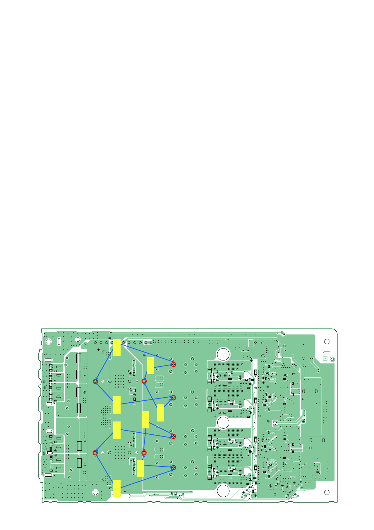
MOSFET Confi rmation for 4CH DAMP Mount (SHAKE33/SHAKE44)
CL1062
CL1035
CL1033
Tester Tes t er
CL1032
C1178C1184
R1227
CL1106
R1263
CL1103
Tester
CL1105
C1224C1232
CL1104
C1169
CL1045
C1182
C1223
CL1050
C1234
Tes t er
C1180
C1183
R1212
CL1107
CL1042
R1234
C1191
C1236
C1237
R1275
CL1046
CL1047
R1286
C1240
CL1036
CL1075
CL1043
C1190
C1239
R1197
C1192
CL1044
CL1048
CL1049
R1199
R1213
R1223
CL1074
R1237
CL1080
CL1079
R1244
R1271
C1241
R1278
R1284
R1289
Tes t er
Tes t er
C1255
R1330
CL1102
C1260
CL1101
R1363
C1302
CL1099
CL1100
C1310
Tes t er
Tester
CL1108
CL1110
R1700
CL1071
R1699
C1517
C1247
C1259
CL1055
C1258
C1268
C1303
C1314
CL1060
C1312
C1317
C1257
R1308
CL1053
CL1051
C1267
CL1052
R1333
R1374
C1316
CL1056
CL1058
CL1057
R1385
R1294
CL1085
C1269
CL1054
C1313
CL1059
CL1016
CL1013
R1296
R1313
CL1084
R1336
R1321
CL1090
R1351
R1350
R1372
C1318
R1376
R1557
R1388
R1382
R1675
R1682
CL1012
R1681
CL1015
CL1014
CL1061
R1316
R1208
C1166
R1646
CL1070
C1209
R1591
R1250
R1352
CL1068
R1604
R1305
C1243
R1592
CL1083
CL1088
R1594
C1285
CL1089
R1609
CL1009
CL1007
CL1040
R1597
CL1041
R1601
CL1039
C1490 C1488
R1602
R1598
CL1038
CL1037
R1636
R1617
C1502
C1504
R1618
R1614
CL1008
CL1001
CL1006
CL1019
CL1067
CL1073
C1026
CL1010
CL1003
CL1002
CL1011
CL1004
CL1109
CL1005
CL1082
<Note>
Please check each channel’s resistance value for the Coil’s terminal and Capacitor’s + and – terminal.
These terminal is equal to resistance value for POWER AUDIO DRIVER terminal.
29
HCD-SHAKE33/SHAKE44/SHAKE55/SHAKE66/SHAKE77/SHAKE88
Ver. 1.1
CL1220
C1512
CL1034
C1145
C1153
CL1031
C1112
C1122
CL1030
C1133
C1140
CL1029
C1125
C1126
CL1028
CL1211
CL1188
CL1219
C1458
CL1033
R1057R1058
CL1193
C1113
R1131
R1157
Tes t er
Tes t er
Tes t er
CL1185
C1070
CL1178
R1428
Tes t er
C1362
CL1022
C1363
C1354
C1358
CL1023
C1374
C1369
CL1024
C1351
C1343
CL1025
CL1212
R1458
CL1175
C1371
R1542
R1541
CL1170
C1511
Tes t er
Tes t er
CL1224
CL1221
CL1035
CL1032
C1071
CL1196
R1062
CL1222
C1055
C1046
CL1197
R1148
C1114
R1083
C1117
Q1018
CL1192
R1128
CL1191
R1150
C1151
C1141
R1164
CL1186
C1372
R1448
C1370
Q1047
R1427
CL1181
R1451
C1400
C1390
R1466
CL1176
C1459
R1540
C1454
R1546
Tes t er
R1142
C1089
C1095
Tes t er
D1019
CL1223
CL1213
D1023
CL1187
Tes t er
R1440
D1047
CL1214
C1342
Tes t er
C1337
CL1182
CL1215
D1051
CL1177
Tes t er
R1533
Q1056
CL1216
Tes t er
CL1172
C1439
C1434
CL1171
CL1226
CL1227
C1047
CL1167
C1057
C1080
CL1162
C1094
C1142
CL1157
C1152
C1324
CL1152
C1340
C1391
CL1145
C1401
C1420
CL1140
C1437
C1059
R1075
C1063
C1067
CL1163
CL1164
R1091
C1069
C1092
R1114
C1093
C1101
CL1158
CL1159
R1136
C1102
C1155
C1156
R1177
C1159
CL1153
CL1154
R1189
C1161
C1339
R1411
C1341
C1349
CL1148
CL1149
R1434
C1352
C1402
R1478
C1403
C1405
CL1143
CL1144
R1489
C1406
C1436
R1526
C1438
C1445
CL1138
CL1139
R1550
C1450
R1048
R1078
C1072
CL1166
R1087
CL1165
R1093
R1099
R1119
C1103
CL1160
R1125
CL1161
R1139
R1146
R1179
C1162
CL1155
R1185
CL1156
R1192
R1394
R1416
C1353
CL1151
R1422
CL1150
R1437
R1450
R1480
C1407
CL1147
R1486
CL1146
R1492
R1502
CL1142
R1529
C1451
R1537
CL1141
R1553
R1557
CL1016
CL1014
CL1015
CL1013
CL1036
CL1133
R1069
CL1135CL1136
R1051
CL1134
C1030
D1082
AK
R1052
CL1137
CL1128
CL1129
R1110
R1116
CL1130CL1131
R1101
C1076
D1083
AK
R1588
CL1132
CL1123
CL1124
R1174
R1168
CL1125
R1154
CL1126
C1121
D1084
AK
R1589
CL1127
CL1118
CL1119
R1406
R1412
CL1120CL1121
R1396
D1085
C1320
AK
R1391
CL1122
CL1113
CL1114
R1474
R1463
CL1115CL1116
R1453
D1086
C1375
AK
R1445
CL1117
CL1111
CL1112
R1496
R1539
CL1109
R1521
CL1108
R1506
C1414
D1087
AK
R1652
CL1110
R1689
CL1006
CL1005
CL1012
CL1010
CL1002
CL1004
CL1008
CL1003
CL1011
CL1007
CL1009
CL1040
CL1039
CL1038
CL1037
CL1210
CL1228
CL1019
CL1001
CL1225
<Note>
Please check each channel’s resistance value for the Coil’s terminal and Capacitor’s + and – terminal.
These terminal is equal to resistance value for POWER AUDIO DRIVER terminal.
B2E2 C1
B1C2 E1
Q1018, Q1047,
Q1056
MOSFET Confi rmation for 6CH DAMP Mount (EXCEPT SHAKE33/SHAKE44)
30
Loading...