


 Loading...
4-232-189-11(1)
Compact AV System
Operating Instructions
Owner’s Record
The model and serial numbers are located at the rear of the unit. Record the serial number in the space provided below. Refer to them whenever you call upon your Sony dealer regarding this product.
Model No. DAV-S300
Serial No.______________
TV |
SLEEP |
|
|
|
FUNCTION |
1 |
2 |
3 |
|
SOUND |
||||
|
|
|
||
FIELD |
4 |
5 |
6 |
|
|
||||
BAND |
7 |
8 |
9 |
|
|
||||
DISPLAY |
|
|
ENTER |
|
|
>10 |
10/0 |
|
|
P.MODE |
AUDIO |
ANGLE |
SUBTITLE |
|
PRESET |
TUNING |
|||
PREV |
NEXT |
|
|
|
PLAY/SELECT |
PAUSE |
STOP |
||
TITLE |
|
DVD MENU |
VOL |
|
|
ENTER |
|
|
|
DVD |
|
|
|
|
DISPLAY |
|
RETURN |
MUTING |
|
DAV-S300
2000 Sony Corporation
WARNING |
Welcome! |
To prevent fire or shock hazard, do not expose the unit to rain or moisture. To avoid electrical shock, do not open the cabinet. Refer servicing to qualified personnel only.
CAUTION
The use of optical instruments with this product will increase eye hazard. As the laser beam used in this CD/DVD Player is harmful to eyes, do not attempt to disassemble the cabinet.
Refer servicing to qualified personnel only.
This label is located on the Laser protective housing inside the enclosure.
This symbol is intended to alert the user to the presence of uninsulated “dangerous voltage” within the product’s enclosure that
may be of sufficient magnitude to constitute a risk of electric shock to persons.
This symbol is intended to alert the user to the presence
of important operating and maintenance (servicing)
instructions in the literature accompanying the appliance.
CAUTION
TO PREVENT ELECTRIC SHOCK MATCH WIDE BLADE OF PLUG TO WIDE SLOT, FULLY INSERT.
For customers in the U.S.A.
CAUTION
You are cautioned that any changes or modifications not expressly approved in this manual could void your authority to operate this equipment.
NOTE:
This equipment has been tested and found to comply with the limits for a Class B digital device, pursuant to Part 15 of the FCC Rules. These limits are designed to provide reasonable protection against harmful interference in a residential installation. This equipment generates, uses, and can radiate radio frequency energy and, if not installed and used in accordance with the instructions, may cause harmful interference to radio communications. However, there is no guarantee that interference will not occur in a particular installation. If this equipment does cause harmful interference to radio or television reception, which can be determined by turning the equipment off and on, the user is encouraged to try to correct the interference by one or more of the following measures:
–Reorient or relocate the receiving antenna.
–Increase the separation between the equipment and receiver.
–Connect the equipment into an outlet on a circuit different from that to which the receiver is connected.
–Consult the dealer or an experienced radio/TV technician for help.
Note on CATV system installer:
This reminder is provided to call the CATV system installer’s attention to Article 82040 of the NEC that provides guidelines for proper grounding and, in particular, specifies that the cable ground shall be connected to the grounding system of the building, as close to the point of cable entry as practical.
CAUTION
TO PREVENT ELECTRIC SHOCK, DO NOT USE THIS POLARIZED AC PLUG WITH AN EXTENSION CORD, RECEPTACLE OR OTHER OUTLET UNLESS THE BLADES CAN BE FULLY INSERTED TO PREVENT BLADE EXPOSURE.
Thank you for purchasing the Sony Compact AV System. Before operating the unit, please read this manual thoroughly and retain it for future reference.
As an ENERGY STAR Partner, Sony Corporation has determined that this product meets the ENERGY STAR guidelines for energy efficiency.
2

TABLE OF CONTENTS
About This Manual 4
This System Can Play the Following Discs 4 Precautions 6
Notes on Discs 6
Getting Started |
7 |
Unpacking 7 |
|
Speaker System Hookup |
8 |
Antenna Hookups 10 |
|
TV and Video Component Hookups 11 |
|
Connecting the AC Power Cord 12 |
|
Selecting the Language for On-Screen Display 13 |
|
Speaker Setup 14 |
|
Presetting Radio Stations |
17 |
|
|
|
|
Playing Discs |
18 |
|
|
|
Playing Discs |
18 |
|
|
|
Selecting a Sound Field 20 |
|
|||
Customizing Sound Fields |
22 |
|
||
Resuming Playback from the Point Where You |
||||
Stopped the Disc (Resume Play) 23 |
||||
Using the Menu for Each DVD |
24 |
|||
Playing VIDEO CDs with PBC Functions (PBC |
||||
Playback) |
25 |
|
|
|
Creating Your Own Program (Program Play) 26 |
||||
Playing in Random Order (Shuffle Play) 27 |
||||
Using the Front Panel Display |
28 |
|||
|
||||
|
||||
Using Various Functions with the |
||||
Control Menu |
30 |
|
|
|
Using the Control Menu Display |
30 |
|||
Control Menu Item List |
32 |
|
||
Searching for the Title/Chapter/Track/Index/Scene
32 |
|
|
|
Checking the Playing Time and Remaining |
|
||
Time 33 |
|
|
|
Selecting a Start Point Using the Time Code |
34 |
||
Changing the Sounds |
35 |
|
|
Displaying the Subtitles |
36 |
|
|
Changing the Angles |
37 |
|
|
Playing Repeatedly (Repeat Play) |
38 |
|
|
Repeating a Specific Portion (AyB Repeat) |
38 |
||
Checking the Play Information |
40 |
|
|
Settings and Adjustments 41 |
|
Using the Setup Display |
41 |
Setup Display Item List |
43 |
Setting the Language for Display and Sound
(LANGUAGE SETUP) 44 |
|
|
Settings for Display (SCREEN SETUP) |
45 |
|
Custom Settings (CUSTOM SETUP) |
46 |
|
Settings for Sound (AUDIO SETUP) |
49 |
|
Settings for Speakers (SPEAKER SETUP) |
49 |
|
|
|
|
|
|
|
Other Operations 51
Controlling the TV with the Supplied Remote 51
Listening to the Radio |
53 |
Naming Preset Stations |
54 |
Using the Sleep Timer |
55 |
|
|
|
|
Additional Information 56
Troubleshooting 56
Self-diagnosis Function 59
Specifications 60
Glossary 61
Language Code List 63
Index to Parts and Controls 64
Index Back cover
3
About This Manual
Conventions
•Instructions in this manual describe the controls on the system. You can also use the controls on the remote if they have the same or similar names as those on the system.
•The icons on the right are used in this manual:
Icon |
Meaning |
|
|
Z |
Indicates that you can use only the remote |
to do the task. |
|
|
|
z |
Indicates tips and hints for making the |
task easier. |
|
|
|
|
Indicates the functions for DVD VIDEOs. |
|
|
|
Indicates the functions for VIDEO CDs. |
|
|
|
Indicates the functions for Audio CDs. |
|
|
This System Can Play the Following Discs
|
DVD VIDEOs |
VIDEO CDs |
Audio CDs |
|||||||||
|
|
|
|
|
|
|
|
|
|
|
|
|
Disc logo |
|
|
|
|
|
|
|
|
|
|
|
|
|
|
|
|
|
|
|
|
|
|
|
|
|
|
|
|
|
|
|
|
|
|
|
|
|
|
|
|
|
|
|
|
|
|
|
|
|
|
|
Contents |
Audio + Video |
Audio + Video |
|
Audio |
||||||||
|
|
|
|
|
|
|
|
|
|
|
|
|
|
|
|
|
|
|
|
|
|
|
|
|
|
Disc size |
12 cm |
8 cm |
12 cm |
|
|
|
8 cm |
12 cm |
|
|
|
8 cm |
|
|
|
|
|
|
|
|
|
|
|
(CD single) |
|
|
|
|
|
|
|
|
|
|
|
|
|
|
Play time |
About 4 h (for |
About 80 min. |
74 min. |
|
|
|
20 min. |
74 min. |
|
|
|
20 min. |
|
single-sided |
(for |
|
|
|
|
|
|
|
|
|
|
|
DVD)/ |
single-sided |
|
|
|
|
|
|
|
|
|
|
|
about 8 h (for |
DVD)/ |
|
|
|
|
|
|
|
|
|
|
|
double-sided |
about 160 min. |
|
|
|
|
|
|
|
|
|
|
|
DVD) |
(for |
|
|
|
|
|
|
|
|
|
|
|
|
double-sided |
|
|
|
|
|
|
|
|
|
|
|
|
DVD) |
|
|
|
|
|
|
|
|
|
|
|
|
|
|
|
|
|
|
|
|
|
|
|
|
|
|
|
|
|
|
|
“DVD VIDEO” logo is a trademark. |
||||
This system conforms to the NTSC color system. You cannot play discs recorded in other color systems such as PAL or SECAM.
Region code of DVDs you can play on this unit
Your system has a region code printed on the back of the unit and will only play DVDs that are labeled with identical region codes.
DVDs labeled ALL will be also played on this unit.
If you try to play any other DVD, the message “Playing this disc prohibited by area limits.” will appear on the
TV screen.
Depending on the DVD, no region code indication may be labeled even though playing the DVD is prohibited
by the area limits.
Region code
MODEL NO.HCD-S300
CD/DVD RECEIVER
SERIAL NO .
Note on playback operations of DVDs and VIDEO CDs
Some playback operations of DVDs and VIDEO CDs may be intentionally fixed by software producers. Since this system plays DVDs
and VIDEO CDs according to the disc contents the software producers designed, some playback features may not be available. Also
refer to the instructions supplied with the DVDs or VIDEO CDs.
4
Terms for discs
• Title
The longest sections of a picture or a music piece on a DVD; a movie, etc., for a picture piece on a video software; or an album, etc., for a music piece on an audio software. Each title is assigned a title number enabling you to locate the title you want.
• Chapter
Sections of a picture or a music piece that are smaller than titles. A title is composed of several chapters. Each chapter is assigned a chapter number enabling you to locate the chapter you want. Depending on the disc, no chapters may be recorded.
• Track
Sections of a picture or a music piece on a VIDEO CD or a CD. Each track is assigned a track number enabling you to locate the track you want.
DVD |
|
|
|
|
|
|
|
|
Disc |
|
||
|
|
|||||||||||
|
|
|
|
|
|
|
|
|
|
|
|
|
structure |
|
|
|
Title |
|
|||||||
|
|
|
|
|
|
|
|
|
|
|
|
|
|
|
|
|
Chapter |
|
|||||||
|
|
|
||||||||||
VIDEO |
|
|
|
|
|
|
|
|
Disc |
|
||
|
|
|
|
|
|
|
|
|
||||
|
|
|
|
|
|
|
|
|
|
|
|
|
CD or |
|
|
|
Track |
|
|||||||
CD |
|
|
|
|
|
|
|
|
|
|
|
|
structure |
|
|
|
|
|
|
|
|
|
|
|
|
|
|
|
Index |
|
||||||||
|
|
|
|
|
||||||||
• Index (CD) / Video Index (VIDEO CD)
A number that divides a track into sections to easily locate the point you want on a VIDEO CD or a CD. Depending on the disc, no indexes may be recorded.
• Scene
On a VIDEO CD with PBC functions, the menu screens, moving pictures and still pictures are divided into sections called “scenes.” Each scene is assigned a scene number enabling you to locate the scene you want.
Note on PBC (Playback Control) (VIDEO CDs)
This system conforms to Ver. 1.1 and Ver. 2.0 of VIDEO CD standards. You can enjoy two kinds of playback according to the disc type.
Disc type |
You can |
|
|
VIDEO CDs |
Enjoy video playback (moving pictures) |
without PBC |
as well as music. |
functions |
|
(Ver. 1.1 discs) |
|
|
|
VIDEO CDs with |
Play interactive software using menu |
PBC functions |
screens displayed on the TV screen (PBC |
(Ver. 2.0 discs) |
Playback), in addition to the video |
|
playback functions of Ver 1.1 discs. |
|
Moreover, you can play high-resolution |
|
still pictures, if they are included on the |
|
disc. |
|
|
Discs that the system cannot play
The system cannot play discs other than the ones listed in the table on page 4. CD-R, CD-ROMs including PHOTO CDs, data sections in CD-EXTRAs, DVD-ROMs etc., cannot be played.
This system incorporates Dolby* Digital and Pro Logic Surround and the DTS** Digital Surround System.
*Manufactured under license from Dolby Laboratories. “Dolby”, “AC-3”, “Pro Logic” and the double-D symbol aare
trademarks of Dolby Laboratories.
Confidential unpublished Works. © 1992-1997 Dolby Laboratories, Inc. All rights reserved.
**Manufactured under license from Digital Theater Systems, Inc. US Pat. No. 5,451,942 and other worldwide patents issued and pending. “DTS” and “DTS Digital Surround” are trademarks of Digital Theater Systems, Inc. © 1996 Digital Theater Systems, Inc. All rights reserved.
This product incorporates copyright protection technology that is protected by method claims of certain U.S. patents and other intellectual property rights owned by Macrovision Corporation and other rights owners. Use of this copyright protection technology must be authorized by Macrovision Corporation, and is intended for home and other limited viewing uses only unless otherwise authorized by Macrovision Corporation. Reverse engineering or disassembly is prohibited.
5
Precautions
On safety
•Caution – The use of optical instruments with this product will increase eye hazard.
•Should any solid object or liquid fall into the cabinet, unplug the system and have it checked by qualified personnel before operating it any further.
On power sources
•The system is not disconnected from the AC power source (mains) as long as it is connected to the wall outlet, even if the system itself has been turned off.
•If you are not going to use the system for a long time, be sure to disconnect the system from the wall outlet. To disconnect the AC power cord (mains lead), grasp the plug itself; never pull the cord.
•Should the AC power cord (mains lead) need to be changed, have it done at a qualified service shop only.
On placement
•Place the system in a location with adequate ventilation to prevent heat build-up in the system.
•Do not place the system on a soft surface such as a rug that might block the ventilation holes on the bottom.
•Do not place the system in a location near heat sources, or in a place subject to direct sunlight, excessive dust or mechanical shock.
•Do not place anything on top of the cabinet that might block the ventilation holes and cause malfunctions.
On operation
•If the system is brought directly from a cold to a warm location, or is placed in a very damp room, moisture may condense on the lenses inside the system. Should this occur, the system may not operate properly. In this case, remove the disc and leave the system turned on for about half an hour until the moisture evaporates.
On adjusting volume
•Do not turn up the volume while listening to a portion with very low level inputs or no audio signals. If you do, the speakers may be damaged when a peak level portion is played.
On cleaning
•Clean the cabinet, panel and controls with a soft cloth slightly moistened with a mild detergent solution. Do not use any type of abrasive pad, scouring powder or solvent such as alcohol or benzine.
On your TV’s color
•If the speakers should cause the TV screen to have color irregularity, turn off the TV at once then turn it on after 15 to 30 minutes. If color irregularity should persist, place the speakers further away from the set.
If you have any questions or problems concerning your system, please consult your nearest Sony dealer.
IMPORTANT NOTICE
Caution: The enclosed system is capable of holding a still video image or On screen display image on your television screen indefinitely. If you leave the still video image or On screen display image displayed on your TV for an extended period of time you risk permanent damage to your television screen. Projection televisions are very susceptible.
Notes on Discs
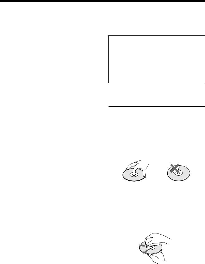
On handling discs
•To keep the disc clean, handle the disc by its edge. Do not touch the surface.
•Do not stick paper or tape on the disc.
If there is glue (or a similar substance) on the disc, remove the glue completely before using the disc.
•Do not expose the disc to direct sunlight or heat sources such as hot air ducts, or leave it in a car parked in direct sunlight as there can be considerable rise in temperature inside the car.
•After playing, store the disc in its case.
On cleaning
•Before playing, clean the disc with a cleaning cloth. Wipe the disc from the center out.
•Do not use solvents such as benzine, thinner, commercially available cleaners or anti-static spray intended for vinyl LPs.
6

Getting
Started
This section describes how to hook up the system to the speakers, a TV monitor with audio/video input jacks and other video component. You cannot connect this system to a TV monitor which does not have a video input connector. Be sure to turn off the power of each component before making the connections.
Unpacking
Check that you have the following items:
•AM loop antenna (1)
•FM wire antenna (1)
•Speakers (5)
•Subwoofer (1)
•Speaker cords (5 m x 4, 15 m x 2)
•Video cord (1)
•Remote commander (remote) RM-SS300 (1)
•Size AA (R6) batteries (2)
•Foot pads (24)
•Speakers – Connection and Installation (card) (1)
Inserting batteries into the remote
You can control the system using the supplied remote. Insert two size AA (R6) batteries by matching the + and – on the batteries. When using the remote, point it at the remote sensor gon the system.
z You can control TVs using the supplied remote
See page 51.
Notes
•Do not leave the remote in an extremely hot or humid place.
•Do not use a new battery with an old one.
•Do not drop any foreign object into the remote casing, particularly when replacing the batteries.
•Do not expose the remote sensor to direct sunlight or lighting apparatuses. Doing so may cause a malfunction.
•If you will not use the remote for an extended period of time, remove the batteries to avoid possible damage from battery leakage and corrosion.
Started Getting
7

Started Getting
Speaker System Hookup
Connect the supplied speaker system using the supplied speaker cords by matching the colors of the terminals and those of the cords.
To obtain the best possible surround sound, specify the speaker parameters (distance, level, etc.) on page 14.
Required cords
Speaker cords (supplied)
The connector and the color tube of the speaker cords are the same color as the label of the terminals to be connected. Connect the striped cord with the + terminal tube to the + terminal.
+ terminal tube
(+)

 (+)
(+)
(–)


 (–)
(–)
Color tube
Terminals for connecting the speakers
Connect the |
To the |
|
|
Front speakers |
SPEAKER FRONT L (white) and |
|
R (red) terminals |
|
|
Rear speakers |
SPEAKER REAR L (blue) and R |
|
(yellow) terminals |
|
|
Center speaker |
SPEAKER CENTER (green) |
|
terminal |
|
|
Subwoofer |
SPEAKER WOOFER (black) |
|
terminal |
|
|
|
Front speaker (R) |
|
|
|
Center speaker |
|
|
|
|
Front speaker (L) |
||||||||||||
|
|
|
|
|
|
|
|
|
|
|
|
|
|
|
|
|
|
|
|
|
|
|
|
|
|
|
|
|
|
|
|
|
|
|
|
|
|
|
|
|
|
|
|
|
|
|
|
|
|
|
|
|
|
|
|
|
|
|
|
|
|
|
|
|
|
|
|
|
|
|
|
|
|
|
|
|
|
|
|
|
|
|
|
|
|
|
|
|
|
|
|
|
Color label |
|
|
|
|
|
||
|
VIDEO OUT |
VIDEO IN |
VIDEO IN |
|
VIDEO |
|
|
|
FM |
|
|
|
|
S VIDEO |
FRONT R |
CENTER |
FRONT L |
75Ω |
AUDIO OUT |
AUDIO IN |
AUDIO IN |
|
(DVD ONLY) |
|
|
|
COAXIAL |
|
L |
|
|
|
|
|
|
|
|
|
|
|
|
|
|
|
|
|
|
|
L |
DIGITAL IN |
|
|
|
|
|
|
|
R |
|
|
|
|
AM |
|
|
|
|
|
|
|
|
|
R |
|
|
|
|
|
|
|
|
|
|
|
OPTICAL |
REAR R |
WOOFER |
REAR L |
|
|
|
|
|
|
|
IMPEDANCE USE 3Ω |
|
|
Rear speaker (R) |
Subwoofer |
Rear speaker (L) |
8

To avoid short-circuiting the speakers
Short-circuiting of the speakers may damage the system. To prevent this, make sure to take the following precautions when connecting the speakers.
Make sure the stripped end of each speaker cord does not touch another speaker terminal or the stripped end of another speaker cord.
Examples of poor conditions of the speaker cord
Stripped speaker cord is touching another speaker terminal.
Stripped cords are touching each other due to excessive removal of insulation.
After connecting all the components, speakers, and AC power cord, output a test tone to check that all the speakers are connected correctly. For details on outputting a test tone, see page 14.
If no sound is heard from a speaker while outputting a test tone or a test tone is output from a speaker other than the one whose name is currently displayed on the front panel display, the speaker may be short-circuited. If this happens, check the speaker connection again.
Notes on speaker system hookup
•Be sure to match the speaker cord to the appropriate terminal on the components: + to + and – to –. If the cords are reversed, the sound will be distorted and will lack bass.
•If you use front speakers with low maximum input rating, adjust the volume carefully to avoid excessive output on the speakers.
If you feel lack of bass frequency
Connect an active subwoofer (not supplied) to the WOOFER OUT jack using a monaural audio cord (not supplied).
When you connect an active subwoofer, disconnect the supplied woofer from the SPEAKER WOOFER terminal.
Black |
Black |
Started Getting
9
Started Getting
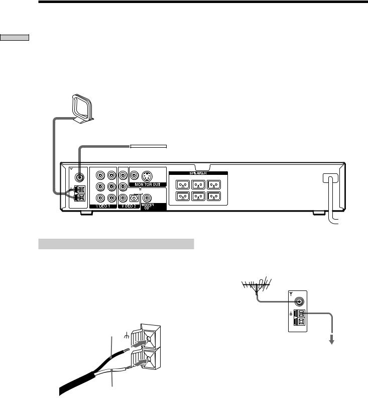
Antenna Hookups
Connect the supplied AM/FM antennas for listening to |
Terminals for connecting the antennas |
|
the radio. |
|
|
|
|
|
|
Connect the |
To the |
|
|
|
|
AM loop antenna |
AM terminals |
|
|
|
|
FM wire antenna |
FM 75Ω COAXIAL terminal |
|
|
|
AM loop antenna (supplied)
FM wire antenna (supplied)
|
VIDEO OUT |
VIDEO IN |
VIDEO IN |
|
VIDEO |
|
|
|
FM |
|
|
|
|
S VIDEO |
FRONT R |
CENTER |
FRONT L |
75Ω |
AUDIO OUT |
AUDIO IN |
AUDIO IN |
|
(DVD ONLY) |
|
|
|
COAXIAL |
|
L |
|
|
|
|
|
|
|
|
|
|
|
|
|
|
|
|
|
|
|
L |
DIGITAL IN |
|
|
|
|
|
|
|
R |
|
|
|
|
AM |
|
|
|
|
|
|
|
|
|
R |
|
|
|
|
|
|
|
|
|
|
|
OPTICAL |
REAR R |
WOOFER |
REAR L |
|
|
|
|
|
|
|
|
|
IMPEDANCE USE 3Ω
Notes on antenna hookups
•To prevent noise pickup, keep the AM loop antenna away from the system and other components.
•Be sure to fully extend the FM wire antenna.
•After connecting the FM wire antenna, keep it as horizontal as possible.
•When you connect the supplied AM loop antenna, connect the black cord (A) to the U terminal, and the white cord (B) to the other terminal.
A
AM
B
z If you have poor FM reception
Use a 75-ohm coaxial cable (not supplied) to connect the system to an outdoor FM antenna as shown below.
Outdoor FM antenna |
System |
|
|
FM |
Ground wire |
|
75Ω |
(not supplied) |
|
COAXIAL |
|
|
AM |
|
|
|
To ground |
Important
If you connect the system to an outdoor antenna, ground it against lightning. To prevent a gas explosion, do not connect the ground wire to a gas pipe.
10
TV and Video Component Hookups
Required cords
Video cord for connecting a TV monitor (supplied)
Yellow 
 Yellow
Audio/video cords (not supplied)
When connecting a cord, be sure to match the color-coded pins to the appropriate jacks on the components.
Yellow (video) |
Yellow (video) |
White (L/audio) 
 White (L/audio)
Red (R/audio) |
Red (R/audio) |
Jacks for connecting video components
Connect a |
To the |
|
|
TV monitor |
MONITOR OUT jack |
|
|
VCR |
VIDEO 1 jacks |
|
|
Digital satellite receiver |
VIDEO 2 jacks |
|
|
z When using the S-video jack instead of the video jacks
Your TV monitor must also be connected via an S-video jack. S- video signals are on a separate bus from the video signals and will not be output through the video jacks.
Note
The VIDEO 1 AUDIO OUT L/R jacks output the same signal as the front L/R speakers. When you select VIDEO 1 using the FUNCTION button, the signal is output from the front L/R speakers, but not from the VIDEO 1 VIDEO OUT and AUDIO OUT L/R jacks.
|
VIDEO OUT |
VIDEO IN |
VIDEO IN |
|
VIDEO |
|
|
|
FM |
|
|
|
|
S VIDEO |
FRONT R |
CENTER |
FRONT L |
75Ω |
AUDIO OUT |
AUDIO IN |
AUDIO IN |
|
(DVD ONLY) |
|
|
|
COAXIAL |
|
L |
|
|
|
|
|
|
|
|
|
|
|
|
|
|
|
|
|
|
|
L |
DIGITAL IN |
|
|
|
|
|
|
|
R |
|
|
|
|
AM |
|
|
|
|
|
|
|
|
|
R |
|
|
|
|
|
|
|
|
|
|
|
OPTICAL |
REAR R |
WOOFER |
REAR L |
|
|
|
|
|
|
|
|
|
IMPEDANCE USE 3Ω
Started Getting
IN |
OUT |
OUT |
OUT |
IN |
INPUT OUTPUT |
OUTPUT |
|
INPUT |
|
VIDEO |
VIDEO |
VIDEO |
|
|
|
VIDEO |
|||
IN |
OUT |
OUT |
|
|
|
IN |
|||
|
|
|
|
|
AUDIO |
AUDIO |
AUDIO |
|
|
IN |
OUT |
OUT |
|
|
|
L |
L |
OUTPUT |
|
|
R |
R |
|
|
|
|
|
OPTICAL |
|
VCR |
Digital satellite receiver |
TV monitor |
|
If you connect a digital satellite receiver with the |
If you connect a digital satellite receiver without |
||
OPTICAL jack |
|
the OPTICAL jack |
|
The digital satellite receiver can be connected to the |
Connect the digital satellite receiver to the VIDEO IN and |
||
OPTICAL jack besides the VIDEO IN and AUDIO IN L/R |
AUDIO IN L/R jacks only of the system. |
||
jacks of the system. |
|
|
|
The system can input both the digital and analog signals. The digital signal has priority to be input. If the digital signal ceases, the analog signal will be input after two seconds.
11

Started Getting
Connecting the AC Power Cord
Before connecting the AC power cord of this system to a wall outlet, connect the speakers to the system (see page 8).
Connect the AC power cord(s) of your TV/video components to a wall outlet.
12
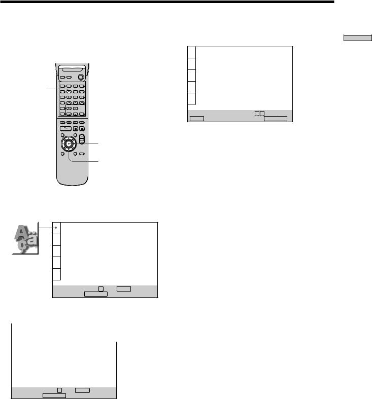
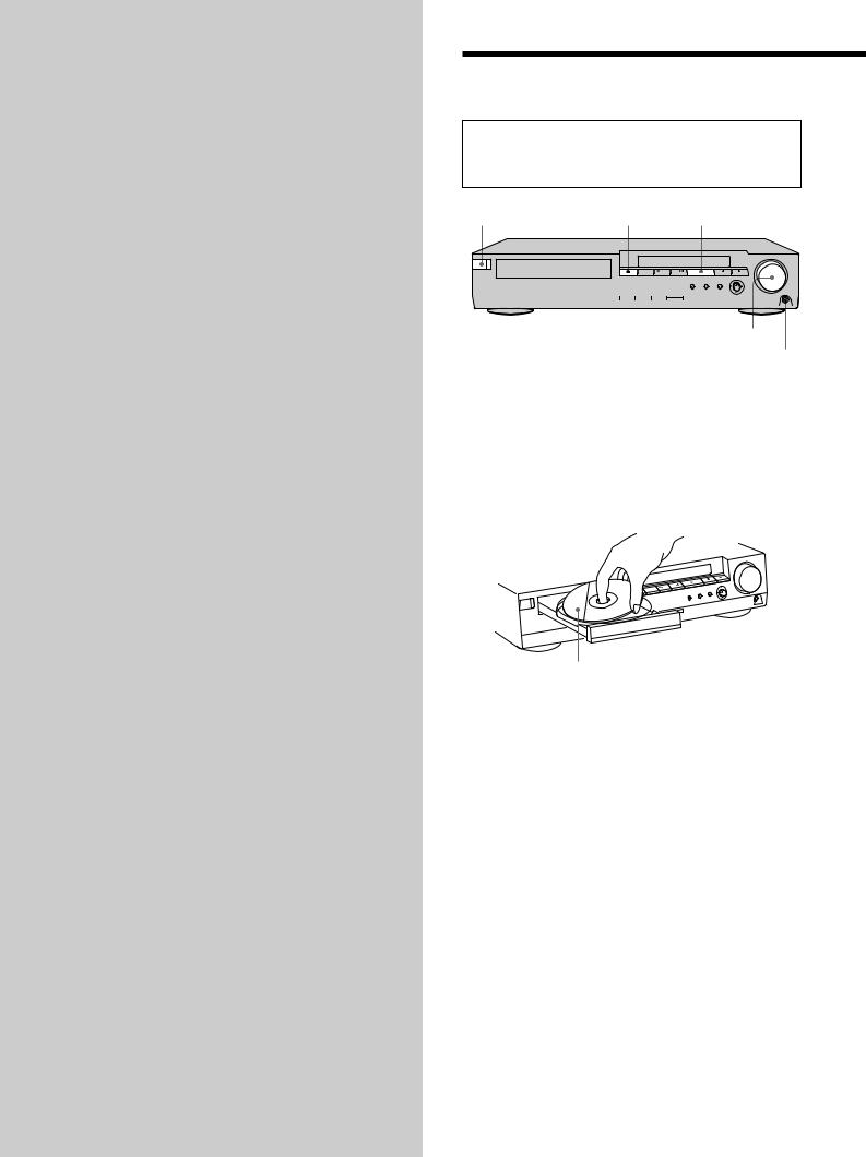
Selecting the Language for On-Screen Display
You can select the language for the setup display, the Control Menu display or the messages displayed on the screen. The default setting is “ENGLISH.”
Open the cover.
DVD SETUP
ENTER
</M/m/,
1Press DVD SETUP and select “LANGUAGE SETUP” using M/m, and then press ENTER.
|
|
|
LANGUAGE SETUP |
|
|
|
|
|
|
OSD: |
ENGLISH |
|
|
|
|
DVD MENU: |
ENGLISH |
|
|
|
|
AUDIO: |
ORIGINAL |
|
|
|
|
SUBTITLE: |
AUDIO FOLLOW |
|
|
|
|
|
|
3 Select “FRENCH” using M/m, then press ENTER.
|
CHOIX DE LA LANGUE |
|
|
|
|
ÉCRANS: |
FRANÇAIS |
|
|
MENU DVD : |
ANGLAIS |
|
|
AUDIO: |
ORIGINAL |
|
|
SOUS-TITRE: |
IDEM AUDIO |
|
|
|
|
Pour régler, appuyez sur 


 , puis sur
ENTER . Pour quitter, appuyez sur SETUPDVDSETUP. .
4 Press DVD SETUP to exit menu.
To cancel using the setup display
Press DVD SETUP again.
Note
The languages you can select are the ones displayed in Step 2. For details, see page 44.
To set, press 


 , then ENTER .
To quit, press SETUPDVDSETUP. .
2 Select “OSD” using M/m, then press , or ENTER.
|
LANGUAGE SETUP |
|
|
|
|
OSD: |
ENGLISH |
|
|
DVD MENU: |
ENGLISH |
|
|
AUDIO: |
FRENCH |
|
|
SUBTITLE: |
SPANISH |
|
|
|
PORTUGUESE |
|
|
|
|
|
|
|
|
To set, press 


 , then ENTER .
To quit, press DVDSETUPSETUP. .
Started Getting
13
Started Getting
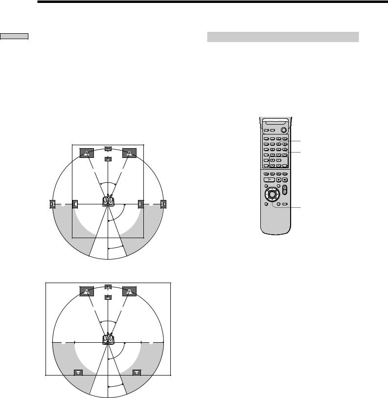
Speaker Setup
For the best possible surround sound all the speakers other than the subwoofer should be the same distance from the listening position (A).
However, this system lets you to place the center speaker up to 5 feet closer (B) and the rear speakers up to 15 feet closer (C) to the listening position.
The front speakers can be placed from 3 to 50 feet (A) from the listening position.
You can place the subwoofer at any position.
You can place the rear speakers either behind you or to the side, depending on the shape of your room, etc.
When the rear speakers are placed to the side
B |
A A
45°
C |
C |
90°
Specifying the speaker parameters
To obtain the best possible surround sound, first specify the distance of the speakers from your listening position, then set the balance and level. Use the test tone to adjust the speaker volumes to the same level.
Details of each item will follow the description of the operation.
You may adjust the speaker parameters using SPEAKER SETUP in the setup display (p. 49).
Open the cover.
AMP MENU
TEST TONE
</M/m/,
20°
When the rear speakers are placed behind you
To specify the size, distance, position and height of the speakers
1Press AMP MENU repeatedly to display << SP. >> on the front panel display.
B |
A A
45°
C |
C |
90°
20°
Note
Do not place the center and rear speakers farther away from the listening position than the front speakers.
2Sit at your listening position and select the item to be set using M/m.
•Items set in << SP. >>
-Size of the rear and center speakers
-Distance of the front, rear and center speakers
-Position and height of the rear speakers
3Set the parameter using </,.
The selected parameter will appear on the front panel display.
4Repeat Steps 2 and 3 to set other parameters within << SP. >>.
If you do not operate the remote for a few seconds, the parameter turns off and is stored in the system.
14

xSIZE
When you do not connect center or rear speakers, or move the rear speakers, set the parameters for CENTER and REAR. Since the front speaker and subwoofer settings are fixed, you cannot change them. The default settings are underlined.
•CENTER (center speaker)
—YES: Normally select this.
—NO: If you will not connect a center speaker, select this.
•REAR (rear speakers)
—YES: Normally select this. Specify the position and height to implement the Digital Cinema Surround modes in the “Virtual” sound field (p. 20) properly.
—NO: If you will not connect a rear speaker, select this.
xDISTANCE
You can vary the distance of each speaker as follows. The default adjustments are in the parentheses.
•F. DIST. (17ft) (front speakers distance)
Front speaker distance can be set in 1 foot steps from 3 to 50 feet.
•C. DIST. (17ft) (center speaker distance)
Center speaker distance can be set in 1 foot steps from a distance equal to the front speaker distance to a distance 5 feet closer to your listening position.
•R. DIST. (12ft) (rear speakers distance)
Rear speaker distance can be set in 1 foot steps from a distance equal to the front speaker distance to a distance 15 feet closer to your listening position.
Note
If each of the front or rear speakers are not placed an equal distance from your listening position, set the distance of the closest speaker.
xPOSITION/HEIGHT
When you select “YES” in “REAR,” specify the position and height of the rear speakers. The default settings are underlined.
Position diagram
|
90° |
A |
A |
|
45° |
B |
B |
|
20° |
•R. PL. BEHIND
Select this if the rear speakers are located in the section
B.
•R. PL. SIDE
Select this if the rear speakers are located in the section
A.
Height diagram
C 
 C
C
 60
60
DD
30
•R. HGT. LOW
Select this if the rear speakers are located in the section
D.
•R. HGT. HIGH
Select this if the rear speakers are located in the section
C.
These parameters are not available when “REAR“ is set to “NO”.
Started Getting
15
Started Getting
Speaker Setup
To specify the balance and level of the speakers
1Press TEST TONE on the remote.
You will hear the test tone from each speaker in sequence.
2Press AMP MENU repeatedly to display <<LEVEL >> on the front panel display.
3Sit at your listening position and select the item to be adjusted using M/m.
•Items adjusted in << LEVEL >>
-Balance of the front and rear speakers
-Volume level of the center and rear speakers and subwoofer
4Adjust the volume level so that the volume of the test tone from each speaker sounds the same using
</,.
The adjusted value will appear on the front panel display.
5Repeat Steps 3 and 4 to adjust other parameters within <<LEVEL>>.
If you do not operate the remote for a few seconds, the value turns off and is stored in the system.
6Press TEST TONE again to turn off the test tone.
xBALANCE
You can vary the balance of each speaker as follows. The default adjustments are in the parentheses.
•F ___I___ (center) (front speakers)
Adjust the balance between the front left and right speakers (6 dB (L) to 6 dB (R), 1 dB steps).
•R ___I___ (center) (rear speakers)
Adjust the balance between the rear left and right speakers (6 dB (L) to 6 dB (R), 1 dB steps).
xLEVEL
You can vary the level of each speaker as follows. The default adjustments are in the parentheses.
•C. LEVEL (0 dB) (center speaker level)
Adjust the level of the center speaker (–6 dB to +6 dB,
1dB steps).
•R. LEVEL (0 dB) (rear speakers level)
Adjust the level of the rear speakers (–6 dB to +6 dB,
1dB steps).
•S. W. LEVEL (0 dB) (subwoofer level)
Adjust the level of the subwoofer (–6 dB to +6 dB,
1dB steps).
zYou can adjust the level of center/rear speakers and subwoofer directly
Use the CENTER/REAR/WOOFER +/– buttons on the remote.
Notes
•When you select an item, the sound cuts off for a moment.
•Depending on the settings of other speakers, the subwoofer may output excessive sound.
To adjust the volume of all the speakers at one time
Use the VOLUME control.
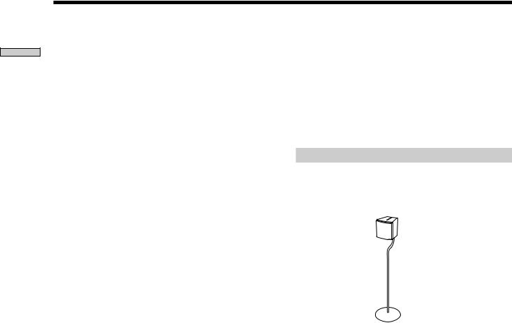
Using the optional speaker stands
For greater flexibility in the positioning of the speakers, use the optional WS-FV10 floor stand (available only in certain countries).
WS-FV10 floor stand
16
Presetting Radio Stations
You can preset 20 stations for FM and 10 stations of AM. Before tuning, make sure that you have turned down the volume to the minimum.
|
1 |
2 |
3 |
|
4 |
5 |
6 |
BAND |
7 |
8 |
9 |
|
>10 |
10/0 |
|
PRESET +/– |
|
TUNING +/– |
MEMORY |
|
|
ENTER |
|
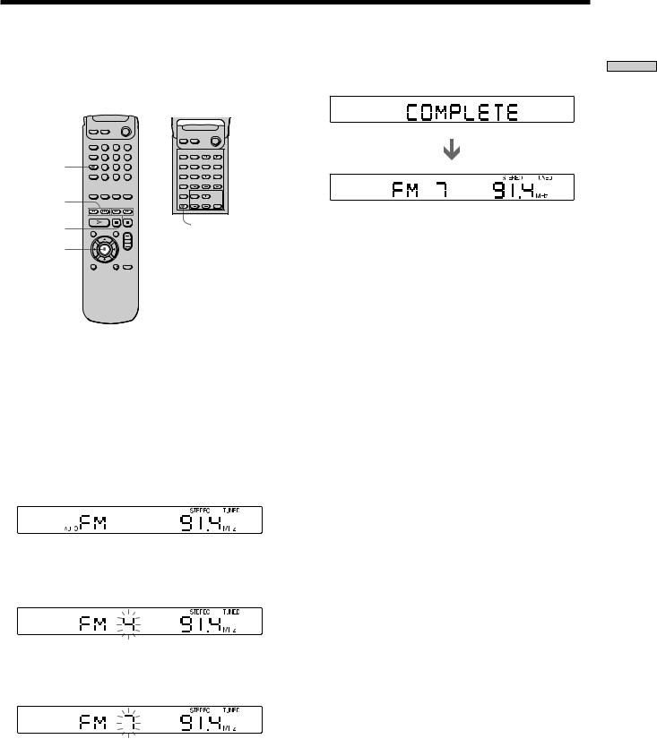
1Press BAND repeatedly until the band you want appears on the front panel display.
Every time you press BAND, FM and AM changes alternately.
2Press and hold TUNING + or – until the frequency indication starts to change, then release.
Scanning stops when the system tunes in a station. “TUNED” and “STEREO” (for stereo program) appear on the front panel display.
3Press MEMORY.
A preset number appears on the front panel display.
4Press PRESET + or – to select the preset number you want.
5Press ENTER.
The station is stored.
6 Repeat Steps 1 to 5 to store other stations.
To tune in a station with a weak signal
Press TUNING + or – repeatedly in Step 2 to tune in the station manually.
To change the preset number
Start over from Step 1.
To change the AM tuning interval
The AM tuning interval is factory set to 10 kHz.
To change the AM tuning interval, tune in any AM station first, then turn off the power. While holding down the ENTER button, turn the power back on. When you change the interval, AM preset stations will be erased.
To reset the interval, repeat the same procedure.
Started Getting
17
Playing Discs
This chapter describes how to play a DVD/CD/VIDEO CD.
Playing Discs 


Depending on the DVD or VIDEO CD, some operations may be different or restricted. Refer to the instructions supplied with your disc.
?/1 (POWER) |
A |
H |
|
|
|
|||
|
|
|
|
|
|
|
|
|
|
|
|
|
|
|
|
|
|
|
|
|
|
|
|
|
|
|
|
|
|
|
|
|
|
|
|
|
|
|
|
|
|
|
|
|
|
|
|
|
|
|
|
|
|
|
|
|
|
|
|
|
|
|
|
|
|
|
|
|
|
|
|
|
|
|
|
|
|
|
|
|
Adjust the volume.
Connect headphones.
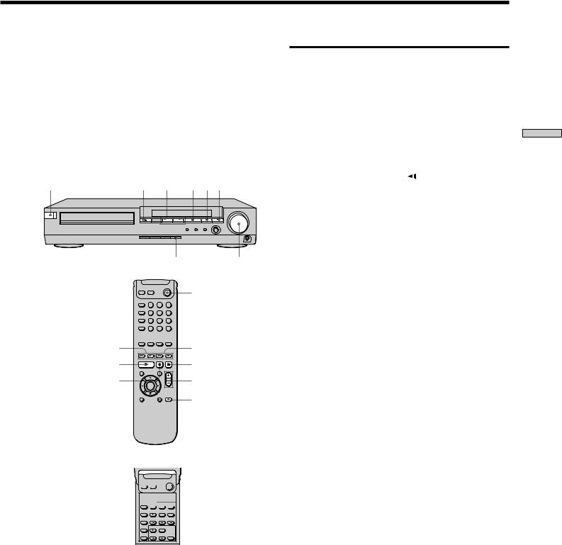
1Turn on the TV and select the video input so that you can view the pictures from this system.
2Press ?/1 (POWER) to turn on the system.
The ?/1 (POWER) button changes to green and the front panel display lights up.
3Press A, and place the disc on the disc tray.
With the playback side facing down
4Press H.
The disc tray closes, and the system starts playback (continuous play). Adjust the volume by rotating VOLUME.
After following Step 4 xWhen playing a DVD
A DVD menu or title menu may appear on the TV screen (see page 24).
xWhen playing a VIDEO CD
The menu screen may appear on the TV screen depending on the VIDEO CD. You can play the disc interactively, following the instructions on the menu screen. (PBC Playback, see page 25.)
18
zYou can turn on the system using the remote
Press ?/1 (POWER) when the indicator by the ?/1 (POWER) button on the front panel is lit in red.
Notes
•If you leave the system in pause or stop mode for 15 minutes, the screen saver image appears automatically. To make the screen saver image go away, press H. (If you want to set the screen saver function to off, see page 45.)
•The indicator by the ?/1 (POWER) button lights up in red when the power is turned off.
?/1 (POWER) |
A ./> H X x |
MUTING |
VOLUME |
|
|
?/1 (POWER) |
1 |
2 |
3 |
4 |
5 |
6 |
7 |
8 |
9 |
>10 |
10/0 |
|
./> |
|
m/M |
H |
|
x |
X |
|
VOL |
|
|
MUTING |


 /y
/y
To |
Operation |
|
Adjust the volume |
Rotate VOLUME or press VOL +/–. |
|
|
|
|
Stop |
Press x. |
|
|
|
|
Pause |
Press X. |
|
|
|
|
Resume play after pause |
Press X or H. |
|
|
|
|
Locate a point quickly |
Press m or M while playing a |
|
|
disc. When you find the point you |
|
|
want, press H to return to the |
|
|
normal speed. |
|
|
|
|
Play in slow motion |
Press |
or y. |
|
|
|
Go to the next chapter, |
Press >. |
|
track or scene in |
|
|
continuous play mode |
|
|
|
|
|
Go back to the preceding |
Press .. |
|
chapter, track or scene in |
|
|
continuous play mode |
|
|
|
|
|
Mute the sound |
Press MUTING. To cancel muting, |
|
|
press it again or turn up the |
|
|
volume. |
|
|
|
|
Stop play and remove the |
Press A. |
|
disc |
|
|
|
|
|
Discs Playing
19
Discs Playing
Selecting a Sound Field


You can enjoy surround sound simply by selecting one of the pre-programmed sound fields according to the program you want to listen to.
SOUND FIELD
1 2 3
SOUND FIELD  4 5 6
4 5 6
DISPLAY |
7 |
8 |
9 |
>10 |
10/0 |
|
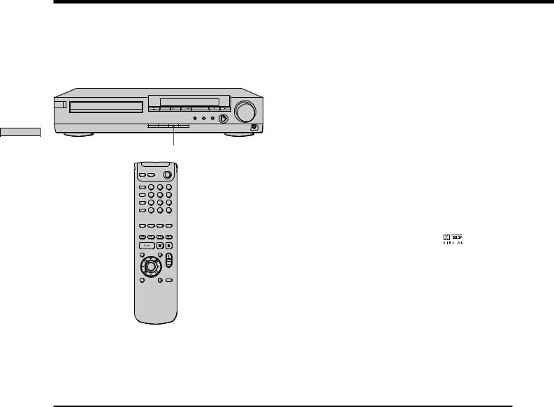
Press SOUND FIELD repeatedly until the sound field you want appears on the front panel display.
See the table below for information on each sound field.
To check the current sound field
Press DISPLAY repeatedly.
Each time you press DISPLAY, the front panel display switches:
remaining or playing time t sound field t remaining or playing time
zThe system memorizes the last sound field selected for each program source (Sound Field Link)
Whenever you select a program source, the sound field that was last applied is automatically applied again. For example, if you listen to DVD with HALL as the sound field, change to a different program source, then return to DVD, HALL will be applied again. With the tuner, sound fields are memorized separately for all preset stations.
zYou can identify the encoding format of program software by looking at its packaging
– Dolby Digital discs are labeled with the |
logo. |
–Dolby Surround encoded programs are labeled with the Alogo.
–DTS Digital Surround discs are marked with DTS.
Note
When you play sound tracks with 96 kHz sampling frequency, the output signals will be converted to 48 kHz (sampling frequency).
Sound field |
Effect |
Notes |
AUTO FORMAT DECODE |
Automatically detects the type of audio signal being |
You can use this mode as a reference. |
|
input (Dolby Digital, DTS, Dolby Pro Logic, or standard |
|
|
2 channel stereo) and performs the proper decoding if |
|
|
necessary. This mode presents the sound as it was |
|
|
recorded/encoded, without adding any effects. |
|
|
|
|
NORMAL SURROUND |
Software with multichannel surround audio signals is |
|
|
played according to the way it was recorded. |
|
|
Software with 2 channel audio signals, is decoded with |
|
|
Dolby Pro Logic to create surround effects. |
|
|
|
|
CINEMA STUDIO A* |
Reproduces the sound characteristics of the Sony |
This is a standard mode, great for |
|
Pictures Entertainment “Cary Grant Theater” cinema |
watching most any type of movie. |
|
production studio. |
|
|
|
|
CINEMA STUDIO B* |
Reproduces the sound characteristics of the Sony |
This mode is ideal for watching science- |
|
Pictures Entertainment “Kim Novak Theater” cinema |
fiction or action movies with lots of sound |
|
production studio. |
effects. |
|
|
|
CINEMA STUDIO C* |
Reproduces the sound characteristics of the Sony |
This mode is ideal for watching musicals |
|
Pictures Entertainment scoring stage. |
or classic films where music is featured in |
|
|
the soundtrack. |
|
|
|
* “VIRTUAL” sound field: Sound field with virtual speakers.
20
Sound field |
Effect |
Notes |
V. MULTI DIMENSION*
(Virtual Multi Dimension)
Uses 3D sound imaging to create an array of virtual rear |
L |
C |
R |
speakers positioned higher than the listener from a |
SIDE* |
|
|
single pair of actual rear speakers. This mode creates 5 |
|
|
|
|
|
|
|
sets of virtual speakers surrounding the listener at |
LS |
|
RS |
|
|
|
|
approximately a 30° angle of elevation. |
|
|
|
|
LS |
|
RS |
|
|
LS |
RS |
|
L |
C |
R |
|
|
BEHIND* |
|
|
|
|
|
LS |
|
|
RS |
|
|
LS |
|
RS |
|
|
|
|
LS |
RS |
* See |
|
|
|
|
|
|
|
|
|
|
|
page 15. |
V. SEMI-M. DIMENSION* |
Uses 3D sound imaging to create virtual rear speakers |
L |
C |
R |
|
(Virtual Semi Multi Dimension) |
from the sound of the front speakers without using |
|
|
|
|
|
actual rear speakers. This mode creates 5 sets of virtual |
LS |
|
|
RS |
|
speakers surrounding the listener at a 30° angle of |
|
|
||
|
|
|
|
|
|
|
elevation. |
|
|
|
|
|
|
LS |
|
RS |
|
|
|
|
LS |
RS |
|
HALL |
Reproduces the acoustics of a rectangular concert hall. |
Ideal for soft acoustic sounds. |
|||
JAZZ CLUB |
Reproduces the acoustics of a jazz club. |
|
|
|
|
LIVE HOUSE |
Reproduces the acoustics of a 300-seat live house. |
Great for rock or pop music. |
|
||
GAME |
Obtains maximum audio impact from video game |
Be sure to set the game machine to stereo |
|||
|
software. |
mode when using game software with |
|||
|
|
stereo sound capabilities. |
|
||
2 CH STEREO |
Outputs the sound from the front left and right |
This allows you to play any source using |
|||
|
speakers and subwoofer. Standard two channel (stereo) |
only the front left and right speakers and |
|||
|
sources completely bypass the sound field processing. |
subwoofer. |
|
|
|
|
Multi channel surround formats are downmixed to two |
|
|
|
|
|
channels. |
|
|
|
|
* “VIRTUAL” sound field: Sound field with virtual speakers.
Notes
•The effects provided by the virtual speakers may cause increased noise in the playback signal.
•When listening to sound fields that employ the virtual speakers, you will not be able to hear any sound coming directly from the rear speakers.
Discs Playing
21
Loading...