


HCD-W550
SERVICE MANUAL
Canadian Model
AEP Model
UK Model
E Model
Australian Model
Tourist Model
•HCD-W550 is the deck, CD section in MHC-W550/W770AV.
Manufactured under license from Dolby Laboratories Licensing Corporation.
“DOLBY” and the double-D symbol aare trademarks of Dolby Laboratories Licensing Corporation.
CD |
Model Name Using Similar Mechanism |
HCD-GR8/RX90 |
|
|
|
||
CD Mechanism Type |
CDM38-5BD29A |
||
Section |
|||
|
|
||
Base Unit Name |
BU-5BD29A |
||
|
|||
|
|
|
|
Tape deck |
Model Name Using Similar Mechanism |
HCD-GR5/RX50 |
|
|
|
|
|
Section |
Tape Transport Mechanism Type |
TCM-220WR2E |
|
|
|
|
SPECIFICATIONS
CD player section |
|
system |
Compact disc and digital |
|
audio system |
Laser |
Semiconductor laser |
|
(l = 780 mm) |
|
Emission duration : |
|
continuous |
Laser output |
Max. 44.6 mW* |
|
*This output is the value |
|
measured at a distance of |
|
200 mm from the |
|
objective lens surface on |
|
the Optical Pick-up Block |
|
with 7 mm aperture. |
Frequency response |
2Hz - 20 kHz (± 0.5dB) |
Wavelenght |
780 - 790 mm |
Signal to noise ratio |
More than 90 dB |
Dynamic renge |
More than 90 dB |
CD OPTICAL DIGITAL OUT |
|
(Square optical connector jack, rear panel) |
|
Wavelength |
600 mm |
Output Level |
- 18 dBm |
Tape player section
Recording system |
4 track 2 channel stereo |
Frequency response |
60 - 13,000 Hz (± 3dB), |
(DOLBY NR OFF) |
using Sony TYPE I |
|
cassette |
|
60 - 14,000 Hz (± 3 dB), |
|
using Sony TYPE II |
|
cassette |
General
Dimensions (w / h / d)Approx. 280 ¥ 205 ¥ 359
|
mm |
Mass |
Approx. 4.3 kg |
Design and specifications are subject to change without notice.
STEREO CASSETTE DECK CD PLAYER
MICROFILM
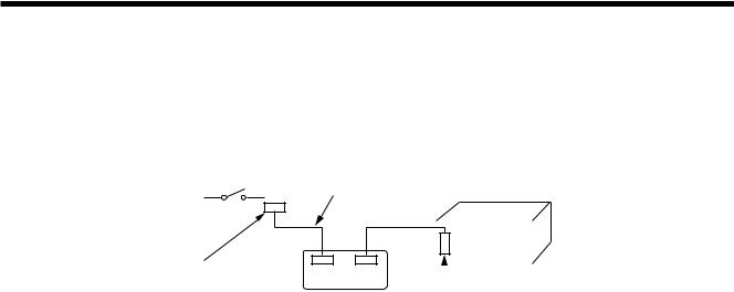
TABLE OF CONTENTS
1.GENERAL ···················································5. EXPLODED VIEWS ··········
|
|
5-1. |
Main Section ····························· |
|
2. |
DISASSEMBLY |
5-2. |
Front Panel Section ·························· |
|
2-1. |
|
5-3. |
CD Mechanism Deck Section-1 (CDM38-5BD29A) ····· 44 |
|
Back Panel, CD Block Removal ········································· 4 |
|
|||
2-2. |
Cassette Lid (A)/(B) Assy, Mechanism Deck Removal ···· 45-4. |
CD Mechanism Deck Section-2 (CDM38-5BD29A) ····· 45 |
|
|
2-3. |
Main Board, Resistor Board, Front Panel Assy Removal ·· 5 |
5-5. |
Base Unit Section (BU-5BD29A) ···················· |
|
|
|
5-6. |
Tape Mechanism Deck Section-1 (TCM-220WR2E) ······ 47 |
|
3. |
ADJUSTMENTS |
5-7. |
Tape Mechanism Deck Section-2 (TCM-220WR2E) ······ 48 |
|
3-1. |
Mechanical Adjustment ··················································· ··· 6 |
|
||
3-2. |
|
6. |
ELECTRICAL PARTS LIST ···················· |
|
Electrical Adjustment ··················································· |
6 |
|||
4.DIAGRAMS
4-1. Block Diagram ··················································· ·········
4-2. Circuit Boards Location ··················································· 13 4-3. Schematic Diagram — Audio Section — ························· 14
4-4. Printed Wiring Board — Audio Section — ······················ 17
4-5. Printed Wiring Board — BD Section — ·························· 19 4-6. Schematic Diagram — BD Section — ····························· 21 4-7. Printed Wiring Board — Motor Section — ······················ 23
4-8. Schematic Diagram — Motor Section — ························ 25 4-9. Schematic Diagram — Panel Section — ························· 27 4-10. Printed Wiring Board — Panel Section — ······················· 29 4-11. Printed Wiring Board — Main Section — ······················· 32 4-12. Schematic Diagram — Main Section — ·························· 35
4-13. IC Block Diagrams ··················································· ········
4-14. IC Pin Function ··················································· ·········
SERVICING NOTE
•Supplying power during servicing
This equipment cannot operate without using a separate power supply. Connect to the STR-W550/W770AV when performing service work.
To apply power set the SYSTEM POWER switch on the Tuner/Amp to ON. When other units are not available use the PFJ-1 power supply jig.
When using the PFJ-1, simultaneously press the CD STOP button and the DECK A )(fast rightward) button to turn on the power.
[Connection Diagram] |
|
PFJ-1 |
|
|
|
|
|
|
|
|
(Power Supply Jig) |
Connector Cable 17P |
|||||
|
|
|
|
|||||
|
|
|
|
(Supplied with set) |
|
|
|
|
|
|
POWER SW |
|
|
|
Set |
||
|
|
|
|
|
|
|
|
|
|
|
|
|
|
|
|
|
|
|
FH-E939,838,737, |
|
|
|
|
|
|
|
|
MHC-6600,5600, |
|
|
|
|
|
|
|
|
|
CNB108 17P |
||||||
|
CDP/TC |
|
Conversion Board |
|||||
|
|
SYSTEM CONTROL |
|
|||||
|
|
|
|
(J-2501-138-A) |
|
|||
|
|
|
|
|
|
|
|
|
— 2 —
SECTION 1
GENERAL
1 23 |
4 5 6 |
7 |
8
9
@° |
|
|
|
|
|
!¼ |
|
|
|||||
|
|
|
|
|
||
@¢ |
|
|
|
|
|
!Á |
|
|
|
|
|
||
@£ |
|
|
|
|
!ª |
|
|
|
|
|
|||
|
|
|
|
|
|
|
|
|
|
|
|
|
|
|
|
|
|
|
|
|
|
|
|
|
|
|
|
|
|
|
@Á |
|
|
!» |
|
!¦ |
|
!° |
|
!£ |
||||
|
|
|
|
|
|
|
|
|
|
|
|
|
|
|
@ª |
|
@¼ |
! |
¥ |
!¤ |
|
!¢ |
|
||||||
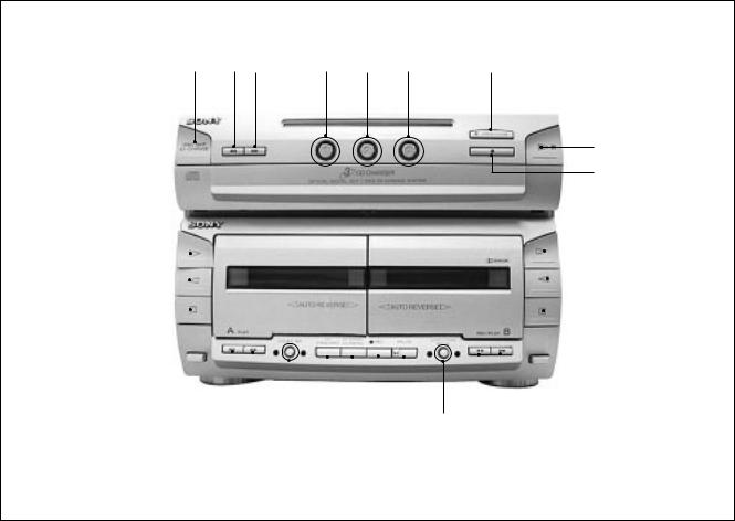
1 |
DISC SKIP EX-CHANGE Button (CD) |
!¢ 0Button [B] (DECK) |
2 |
0 Button (CD) |
!° DIRECTION MODE Button (DECK) |
3 |
) Button (CD) |
!¤ PAUSE Button (DECK) |
4 |
DISC 1 Button (CD) |
!¦ REC Button (DECK) |
5 |
DISC 2 Button (CD) |
!¥ HI-SPEED DUBBING Button (DECK) |
6 |
DISC 3 Button (CD) |
!» CD SYNCHRO Button (DECK) |
7 |
6 OPEN/CLOSE Button (CD) |
@¼ DOLBY NR Button (DECK) |
8 |
áPButton (CD) |
@Á )Button [A] (DECK) |
9 |
p Button (CD) |
@ª 0Button [A] (DECK) |
!¼ á Button [B] (DECK) |
@£ ¹Button [A] (DECK) |
|
!Á » Button [B] (DECK) |
@¢ »Button [A] (DECK) |
|
!ª ¹ Button [B] (DECK) |
@° áButton [A] (DECK) |
|
!£ ) Button [B] (DECK) |
|
|
— 3 —

SECTION 2
DISASSEMBLY
Note : Follow the disassembly procedure in the numerical order given.
2-1. BACK PANEL, CD BLOCK REMOVAL
8 CD block
7 Screw
+BVTP 3 × 10
CASE
Unscrew the five case attachment in the screws (case) (M3 × 8) × 4, (+BV 3 × 8) × 1 and remove the case.
2 Back panel
1 Screw
+BVTP 3 × 10
1 Screw
+BVTP 3 × 10
3 Flat wire (19 core)
4 CN112 (9 pin)
5 CN111 (8 pin)
6 Screw
+BVTP 3 × 10
2-2. CASSETTE LID (A)/(B) ASSY, MECHANISM DECK REMOVAL
1Press the EJECT button and open the cassette lid.
Mechanism Deck (TCM-220WR2E)
8
1 
3
1
7 Screw
+BVTP 2.6 × 8
2
4 Flat wire (11 core)
5 Flat wire (21 core)
6 Screw
+BVTP 3 × 8
— 4 —
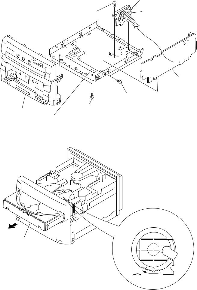
2-3. MAIN BOARD, RESISTOR BOARD, FRONT PANEL ASSY REMOVAL
|
4 Bracket (H/S) |
|
3 Screw |
5 Resistor board |
|
+BVTP 3 × 8 |
||
|
7 Main board
6 Screw
+BVTP 3 × 8
|
1 Screw |
2 Front panel assy |
+BVTP 3 × 8 |
•Tray (Slide) getting out procedure on the power supply is OFF
Rotate the BU CAM assembly in the direction of the arrow and pull out the slide.
Tray (Slide)
1
BU CAM assy
— 5 —
SECTION 3
ADJUSTMENTS
3-1. MECHANICAL ADJUSTMENT
PRECAUTION
1.Clean the following parts with a denatured-alcohol-moistened
swab: |
|
record/playback head |
pinch roller |
erase head |
rubber belts |
capstan |
idlers |
2.Demagnetize the record/playback head with a head demagnetizer.
3.Do not use a magnetized screwdriver for the adjustments.
4.After the adjustments, apply suitable locking compound to the parts adjusted.
5.The adjustments should be performed with the rated power supply voltage unless otherwise noted.
• Torque Measurement
Mode |
Torque Meter |
Meter Reading |
|
Forward |
CQ-102C |
36 to 61g•cm |
|
(0.50 – 0.84 oz•inch) |
|||
|
|
||
|
|
|
|
Forward |
CQ-102C |
2 to 6g•cm |
|
Back Tension |
(0.028 – 0.083 oz•inch) |
||
|
|||
Reverse |
CQ-102RC |
36 to 61g•cm |
|
(0.50 – 0.84 oz•inch) |
|||
|
|
||
|
|
|
|
Reverse |
CQ-102RC |
2 to 6g•cm |
|
Back Tension |
(0.028 – 0.083 oz•inch) |
||
|
|||
|
|
|
|
FF, REW |
CQ-201B |
61 to 143g•cm |
|
(0.85 – 1.99 oz•inch) |
|||
|
|
||
|
|
|
|
• Tape Tension Measurement |
|
||
|
|
|
|
Mode |
Tension Meter |
Meter Reading |
|
Forward |
CQ-403A |
more than 100 g (3.53 oz) |
|
|
|
|
|
Reverse |
CQ-403R |
more than 100 g (3.53 oz) |
|
3-2. ELECTRICAL ADJUSTMENT
DECK SECTION
1.The adjustment should be performed in the publication. (Be sure to make playback adjustment at first.)
2.The adjustment and measurement should be performed for both
L-CH and R-CH. |
|
• Switch position |
|
DOLBY NR switch |
: OFF |
FUNCTION button |
: OFF |
EFFECT switch |
: OFF |
DBFB switch |
: OFF |
3.Deck section electrical adjustments are made in test mode by press key switch same time CD STOP 
 DECK A STOP and DECK B STOP button.
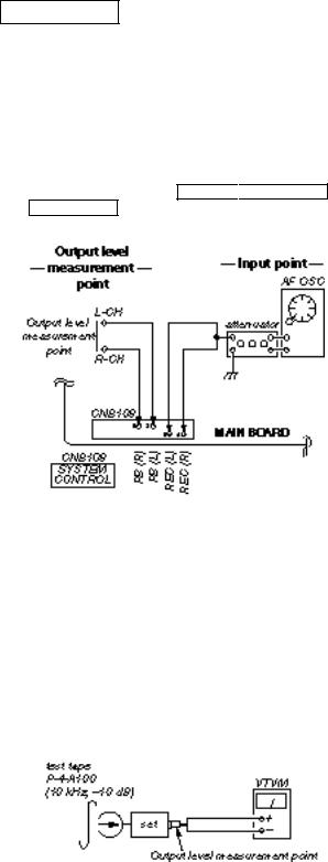
4.Input point and output level measurement point.
•Test Tape
Tape |
|
Signal |
Used for |
|||
|
|
|
|
|
|
|
P-4-A100 |
|
10 kHz, –10 dB |
Head Azimuth Adjustment |
|||
|
|
|
|
|
|
|
P-4-L300 |
|
315 Hz, 0dB |
Level Adjustment |
|||
|
|
|
|
|
|
|
WS-48B |
|
3 kHz, 0dB |
Tape Speed Adjustment |
|||
|
|
|
|
|
|
|
0 dB=0.775V |
|
|
|
|
||
Record/Playback Head Azimuth Adjustment |
||||||
|
|
|
|
|
|
|
DECK A |
|
|
DECK B |
|
|
|
|
|
|
|
|
|
|
Procedure:
1.Forward Playback mode Reverse Playback mode
— 6 —
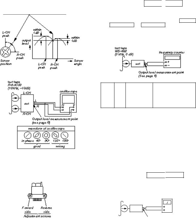
2.Turn the adjustment screw for the maximum output levels. If these levels do not match, turn the adjustment screw until both of output levels match together within 1 dB.
3.Playback Mode
4.Change the playback mode and repeat the steps 1 to 3.
5.After the adjustment, lock the adjustment screw with suitable locking compound.
Adjustment Location:
— Record/playback head (Deck A and B) —
Tape Speed Adjustment DECK A 
 DECK B
Note: Start the Tape Speed adjustment as below after setting to the test mode.
Set to test mode. (Press key switch same time CD STOP DECK A STOP and DECK B STOP button.)
Test mode off. (Power off.)
Procedure:
• Perform high speed adjustment before normal speed adjustment. Mode: Playback
Speed Deck |
Adjustment |
Frequency counter |
||
*High |
A |
RV652 |
5,910 to 6,090 Hz |
|
|
|
|||
B |
RV652 |
|||
|
|
|||
|
|
|
|
|
Normal |
A |
RV651 |
2,910 to 3,090 Hz |
|
|
|
|||
|
|
|||
BRV651
*Continue to press HIGH SPEED DUBBING switch (S259) in playback mode : High speed playback.
Frequency difference between the beginning and the end of the tape should be within ± 3%.
Frequency difference between deck A and deck B the beginning of the tape should be within 1.5 %.
Adjustment Location: AUDIO board (See page 8)
Sample Value of Wow and flutter
W.RMS (JIS) within 0.3% (test tape: WS-48B)
Playback level Adjustment DECK A 
 DECK B
Procedure:
— FWD playback Mode —
test tape |
|
|
P-4-L300 |
VTVM |
|
(315 Hz, 0 dB) |
||
|
||
set |
+ |
|
– |
||
|
Output level measurement point (See page 6)
Deck A is RV311 (L-CH) and RV411 (R-CH), Deck B is RV301 (L-CH) and RV401 (R-CH) so that adjustment within adjustment level as follows.
Adjustment Level:
LINE OUT level : –8.2 to –7.2 dB (301.5 to 338.3 mV) Level Difference between Channels : within 0.5 dB
Confirm the OUTPUT level does not change in playback mode while changing the mode from playback to stop several times.
Adjustment Location: AUDIO board (See page 8)
— 7 —
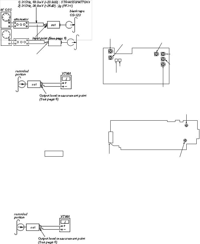
Record Bias Adjustment DECK B
Procedure:
1.Record mode
1)315 Hz üý69.0mV (–23.8dB) : STR-W550/W770AV
2)10 kHz þ38.8mV (–26dB) : jig (PFJ-1)
AF OSC |
blank tape |
|
|
|
CS-123 |
|
attenuator |
|
set |
Input point (See page 6)
2.Mode: Playback
Adjustment Level:
OUTPUT level: –23.8 dB ± 1.0 dB (56.1 to 44.6 mV)
Adjustment Location: MAIN board
Adjustment Location :
[AUDIO BOARD] — Component Side —
RV301 : Playback Level (Deck B L-CH)
RV401 : Palyback Level RV651 : Tape Speed (Normal)
(Deck B R-CH)
|
RV652 : Tape Speed |
|
(Hight) |
RV341 : Record Bias (L-CH) |
RV311 : Playback Level |
(Deck A L-CH) |
|
RV441 : Record Bias (R-CH) |
|
RV411 : Playback Level (Deck A R-CH) |
|
3.Confirm playback the signal recorded in step 1 become adjustment level as follows.
4.If these levels do not adjustment level, adjustment the RV341 (L-CH) and RV441 (R-CH) to repeat steps 1 and 4.
Adjustment level: Playback output of 315 Hz to playback output of 10 kHz: 0 ± 1.0 dB (0 ± 4.5mV).
Adjustment Location: AUDIO board
Record Level Adjustment DECK B
Procedure:
1.Record mode
2.Playback mode
3.Confirm playback the signal recorded in step 1 become adjustment level as follows.
4.If these levels do not adjustment level, adjustment the RV401 (L-CH) and RV451 (R-CH) to repeat steps 1 and 4.
[MAIN BOARD] — Component Side —
RV451 Record Level (R)
CNB108
RV401 Record Level (L)
— 8 —
CD SECTION
Note :
1.CD Block is basically designed to operate without adjustment. Therefore, check each item in order given.
2.Use YEDS-18 disc (3-702-101-01) unless otherwise indicated.
3.Use an oscilloscope with more than 10M impedance.
4.Clean the object lens by an applicator with neutral detergent when the signal level is low than specified value with the following checks.
Focus Bias check
Procedure:
1.Connect oscilloscope to test point TP (RF). (GND terminal : VC)
2.Turned Power switch on.
3.Put disc (YEDS-18) in and playback.
4.Confirm that the shape “ ” can be clearly distinguished at the center of the waveform and check the RF signal level.
• RF signal
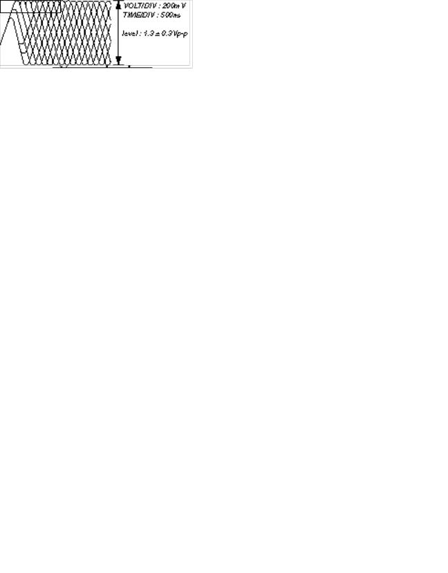
S Curve Check
Procedure:
1.Connect oscilloscope to test point TP (FEO).
2.Connect between test point TP (FOK) and GND by lead wire.
3.Turn Power switch on.
4.Put disc (YEDS-18) in and turned Power switch on again and actuate the focus search. (actuate the focus search when disc table is moving in and out.)
5.Check the oscilloscope waveform (S-curve) is symmetrical between A and B. And confirm peak to peak level within 3±1 Vp-p.
S-curve waveform
6.After check, remove the lead wire connected in step 2.
Note: • Try to measure several times to make sure than the ratio of A : B or B : A is more than 10 : 7.
• Take sweep time as long as possible and light up the brightness to obtain best waveform.
RF Level Check
Procedure:
1.Connect oscilloscope to test point TP (RF) on BD board.
2.Turned Power switch on.
3.Put disc (YEDS-18) in and playback.
4.Confirm that oscilloscope waveform is clear and check RF signal level is correct or not.
Note:
Clear RF signal waveform means that the shape “ ” can be clearly distinguished at the center of the waveform.
• RF signal
— 9 —

E-F Balance (1 Track Jump) check (Without remote commander)
Procedure:
1.Connect oscilloscope to test point TP (TEO) on BD board.
2.Turned Power switch on.
3.Put disc (YEDS-18) in to play the number five track.
4.Press the “P (Pause)” button. (Becomes the 1 track jump mode)
5.Check the level B of the oscilloscope's waveform and the A (DC voltage) of the center of the Traverse waveform. Confirm the following:
A – B × 100 = ±7 (%) 2 (A + B)
1 track jump waveform
Center of the waveform
B
A (DC voltage)
0V
symmetry level : 500 mV ± 100 mVp-p
Adjustment Location:
[BD BOARD] (Conductor Side)
CNU101
TEO
GND
RF
VC
|
FOK |
|
IC101 |
IC |
|
I02 |
||
|
FEO
IC103
CNU102
— 10 —
 Loading...