


TB60

P/N 0082168
January, 2001
DANGER
ELECTRICAL HAZARD
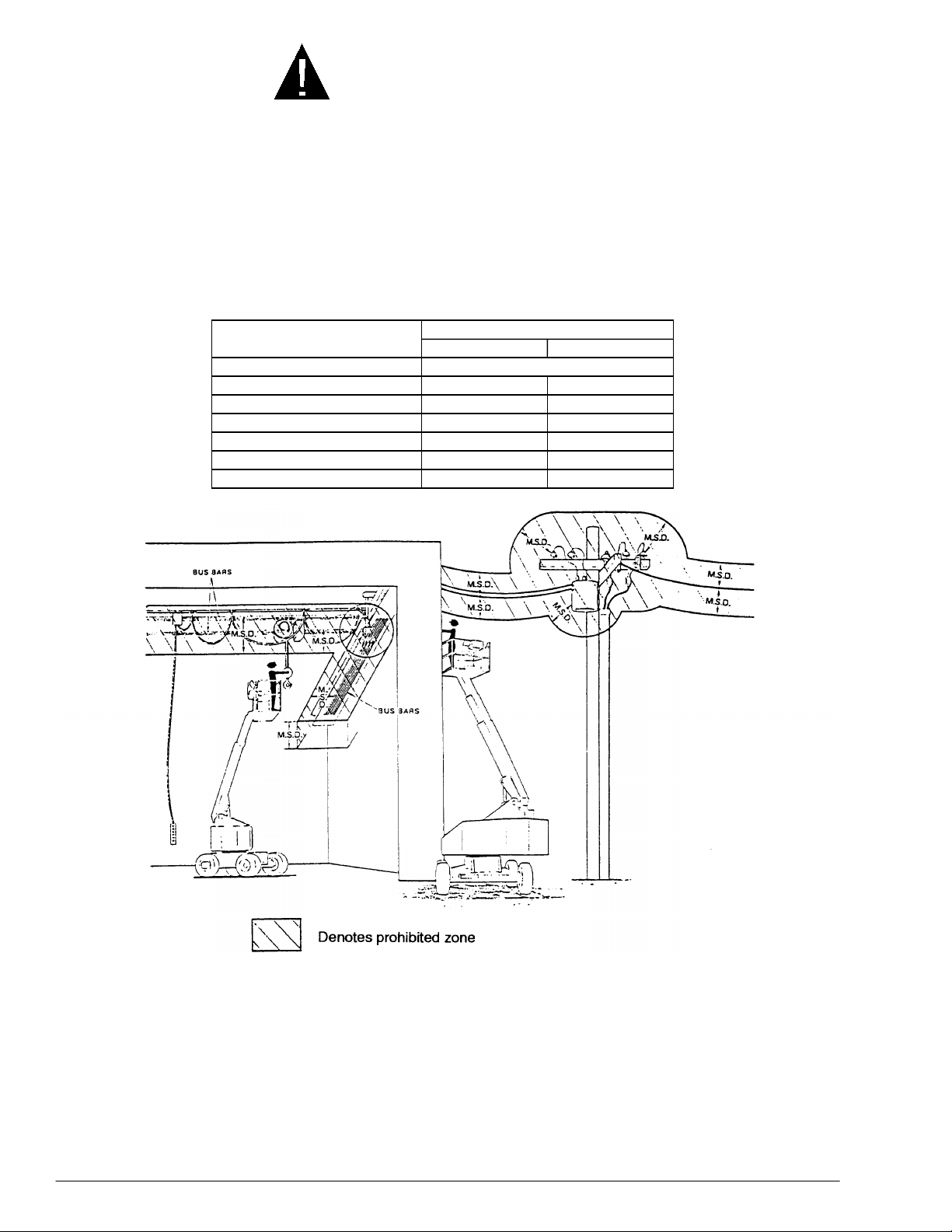
The TB 60 is an all metal boom, NOT ELECTRICALLY INSULATED, aerial work platform. Do
not operate it near ELECTRICAL conductors. Regard all conductors as being energized. Use
the table and figure below to determine safe clearance from electrical conductors. Table 1 and
Figure 3 are reprinted courtesy of Scaffold Industry Association, ANSI/SIA A92.5, page 23.
Table 1 - Minimum safe approac h di stance (M.S.A.D.)
to energized (exposed or insulated power lines
Voltage range
(phase to phase)
0 to 300V Avoid contact
Over 300V to 50KV 10 3.05
Over 50KV to 200KV 15 4.60
Over 200KV to 350KV 20 6.10
Over 350KV to 500KV 25 7.62
Over 500KV to 750KV 35 10.67
Over 750KV to 1000KV 45 13.72
Minimum safe approach di stance
(Feet) (Meters)
Danger: - Do not allow machine personnel or conductive
materials inside prohibited zone.
- Maintain M.S.A.D. from all energized lines and parts
as well as those shown.
- Assume all electrical parts and wires are energized
unless known otherwise.
Caution: - Diagrams shown are only for purposes of illustrating
M.S.A.D. work positions, not all work positions.
Figure 3 - Minimum Safe Approach Distance (M.S.A.D.)
P/N 0082168

DANGER
ELECTRICAL HAZARD
THE TB 60 AERIAL WORK PLATFORM IS NOT
ELECTRICALLY INSULATED.
If the platform, booms, or any other conductive part of a TB 60 contacts a highvoltage electrical conductor, the result can be
persons on or near the machine.
GO NO CLOSER THAN THE MINIMUM SAFE APPROACH
DISTANCES ON THE OPPOSITE PAGE.
Be sure to allow for sag and sway in the wires and the work platform.
If a TB 60 comes in contact with a live electrical conductor, the entire machine
can be charged. If that happens, you should remain on the machine and not
contact any other structure or object within reach. That includes the ground,
adjacent buildings, poles, and any object not a part of the TB 60. Such contact
could make your body a conductor to the other object creating an electrical
shock hazard resulting in
or leave the TB 60 until you are sure the electricity has been turned off.
SERIOUS INJURY
SERIOUS INJURY
DEATH
or
. Do not attempt to enter
or
DEATH
for
If a TB 60 is in contact with a live conductor, the platform operator
others on the ground in the vicinity of the TB 60 to
machine, since their bodies can also form a path for electricity to ground thus
creating an electrical shock hazard with possible
DEATH
Do not attempt to operate the TB 60 ground controls when the platform, booms,
or any other conducting part of a TB 60 is in contact with electrical wires or if
there is an immediate danger of such contact.
Regard all conductors as energized.
Personnel working on or near a TB 60 must be continuously aware of electrical
hazards, recognizing that
an electrical wire does occur.
.
SERIOUS INJURY
or
STAY AWAY
ELECTROCUTION
DEATH
can result if contact with
MUST
from the
and
warn
P/N 0082168
i

TABLE OF CONTENTS
INTRODUCTION.................................................................iii
SIGNS...........................................................................iii
QUALIFIED OPERATORS............................................iii
MAINTENANCE............................................................iii
RESPONSIBILITIES OF PARTIES.............................. iv
ADDITIONAL INFORMATION...................................... iv
1. SAFETY ......................................................................1 - 1
SAFE OPERATION...................................................1 - 1
Pre-start Inspection.................................................1 - 1
Work Place Inspection and Practices.....................1 - 1
Electrocution...........................................................1 - 2
Tipover & Falling Hazards.......................................1 - 2
Crushing .................................................................1 - 2
GENERAL SAFETY PRECAUTIONS........................1 - 2
Personnel Precautions............................................1 - 2
Operator General Precautions................................1 - 2
Mounting & Dismounting Precautions.....................1 - 3
Starting and Stopping Precautions.........................1 - 3
Operating Precautions............................................1 - 3
Operator Maintenance Precautions........................1 - 3
Fuel Handling Precautions......................................1 - 3
SAFETY DECALS & PLACARDS..............................1 - 3
2. SAFETY DEVICES......................................................2 - 1
TILT ALARM & LEVEL SENSOR...............................2 - 1
EMERGENCY STOP SWITCHES.............................2 - 1
LANYARD ANCHOR POINTS...................................2 - 2
GRAVITY GATE........................................................2 - 2
FOOT SWITCH..........................................................2 - 2
GROUND OPERATION SWITCH..............................2 - 3
SELF-CLOSING GATE (option).................................2 - 3
OPERATOR HORN (option)......................................2 - 3
FLASHING LIGHT (option)........................................2 - 3
PLATFORM WORK LIGHTS (option)........................2 - 4
DRIVING LIGHTS (option).........................................2 - 4
MOTION WARNING ALARM (option)........................ 2 - 4
GFCI OUTLET (option)..............................................2 - 4
GUARDRAILS (option) ..............................................2 - 4
3. SPECIFICATIONS ......................................................3 - 1
GENERAL SPECIFICATIONS...................................3 - 1
PLATFORM SPECIFICATIONS.................................3 - 1
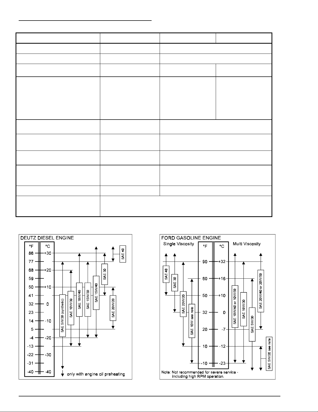
ENGINE DATA...........................................................3 - 2
ENGINE OIL CHARTS...............................................3 - 2
OVERALL DIMENSIONS...........................................3 - 3
WORKING ENVELOPE.............................................3 - 4
SERIAL NUMBER LOCATIONS................................3 - 5
CHASSIS NOMENCLATURE....................................3 - 5
TURNTABLE AND BOOM NOMENCLATURE..........3 - 5
4. GAUGES & CIRCUIT BREAKERS.............................4 - 1
GAUGES ...................................................................4 - 1
FILTER MINDER.....................................................4 - 1
TEMPERATURE.....................................................4 - 1
AMPS......................................................................4 - 1
HOURS...................................................................4 - 1
Fuel.........................................................................4 - 2
Hydraulic Oil Level..................................................4 - 2
Hydraulic Oil Temperature......................................4 - 2
Hydraulic Oil Filter ..................................................4 - 3
Engine Oil...............................................................4 - 3
CIRCUIT BREAKERS................................................4 - 4
5. SIRENS & AUTOMATIC SHUT-OFFS........................5 - 1
SIRENS .....................................................................5 - 1
AUTOMATIC SHUT-OFFS........................................5 - 1
6. CONTROLS................................................................ 6 - 1
GROUND-CONTROL PANEL...................................6 - 2
PLATFORM-CONTROL BOX....................................6 - 4
7. OPERATION...............................................................7 - 1
CONTROL STATIONS..............................................7 - 1
STARTING FROM THE GROUND-
CONTROL PANEL....................................................7 - 1
Pre-start Conditions................................................ 7 - 1
Starting (from the ground) ...................................... 7 - 2
STARTING FROM THE PLATFORM-
CONTROL BOX.........................................................7 - 3
Pre-start Conditions................................................ 7 - 3
Starting (from the platform).....................................7 - 4
MOVING THE PLATFORM........................................7 - 5
MOVING THE TB 60.................................................7 - 8
STEERING................................................................7 - 8
125 V AC OUTLET AT THE PLATFORM..................7 - 9
8. EMERGENCY OPERATION.......................................8 - 1
EMERGENCY STOP.................................................8 - 1
EMERGENCY POWER.............................................8 - 1
Used from ground-control panel.............................8 - 1
Used from platform-control box..............................8 - 2
EMERGENCY BLEED-DOWN..................................8 - 3
9. STOWING & TRANSPORTING..................................9 - 1
STOWING .................................................................9 - 1
TRANSPORTING......................................................9 - 1
Trailering.................................................................9 - 1
Securing to a Transport Vehicle.............................9 - 2
Towing....................................................................9 - 4
10. DAILY INSPECTION & MAINTENANCE................10 - 1
DAILY INSPECTION AND MAINTENANCE.........10 - 1
PLACARDS AND DECALS INSPECTION CHART...10 - 10
PLACARDS AND DECALS INSPECTION DWG........10 - 11
11. TROUBLESHOOTING............................................ 11 - 1
12. OPTIONS................................................................12 - 1
OPERATOR HORN..............................................12 - 1
PLATFORM WORK LIGHTS................................12 - 1
DRIVING LIGHTS.................................................12 - 1
COLD WEATHER START KIT .............................12 - 2
Deutz Engine.....................................................12 - 2
Ford Engine.......................................................12 - 2
HYDRAULIC SYSTEM COLD WEATHER
WARM-UP KIT .....................................................12 - 2
AC GENERATOR.................................................12 - 3
MOTION WARNING ALARM................................12 - 3
AIR LINE TO PLATFORM....................................12 - 3
GFCI OUTLET......................................................12 - 4
FLASHING LIGHT................................................12 - 4
SELF-CLOSING GATE.........................................12 - 4
SPARK ARRESTOR.............................................12 - 4
LIFTING LUGS.....................................................12 - 5
TOW KIT...............................................................12 - 5
13. FIRE FIGHTING & HAZARDOUS
CHEMICAL CONTAINMENT..................................13 - 1
ANTIFREEZE (UN 1993)...................................... 13 - 1
BATTERY, LEAD/ACID (UN 2794).......................13 - 1
DIESEL FUEL (NA 1993) .....................................13 - 1
FOAM IN TIRES...................................................13 - 1
GASOLINE (UN 1203)..........................................13 - 2
HYDRAULIC OIL (UN 1270).................................13 - 2
LIQUEFIED PETROLEUM GAS (UN 1075)..........13 - 2
MOTOR OIL (UN 1270)........................................13 - 2
INDEX..............................................................................I - 1
WARRANTY ..........................................(inside back cover)
ii
P/N 0082168

INTRODUCTION
INTRODUCTION
The most important chapter in t his manual is
“1. SAFETY.” Take time, now, to study it
closely. The information in that chapt er m ight
save your life or prevent serious injury.
SIGNS
The following two conventions are used
throughout this manual.
1. This sign
DANGER
means:
is involved
2. This sign
Attention! Become alert! Your safety
.
CAUTION
means one of two things: (1) an act ion, about t o
be performed, is potentially hazardous and
might result in minor per sonal inj ur y if not done
correctly, or (2) an action, about to be
performed, can damage the TB 60 if not done
correctly.
QUALIFIED OPERATORS
The TB 60 aerial platfor m has built-in safety
features and has been factory tested for
compliance with Snorkel specifications and
industry standards. However, any personnellifting device can be potentially dangerous in
the hands of untrained or careless operat or s.
The following rules will help ensure the
safety of personnel and help prevent
needless downtime because of damaged
equipment.
1. Only TRAINED and AUTHORIZED operators
shall be permitted to operate the eq uipm ent .
2. All manufacturer’s operating instructions and
safety rules and all employers’ safety rules and
all OSHA and other government safety rules
must be strictly adhered to.
3. Repairs and adjustments shall be made only
by QUALIFIED TRAINED maintenance
personnel.
4. No modification shall be made to the
equipment without prior written consent of
Snorkel.
5. You must make a pre-star t inspection of the
TB 60 at the beginning of each shift. A
malfunctioning machine must not be used.
6. You must make an inspection of the work
place to locate possible hazards before
operating the TB 60.
DANGER
Misuse of this machine can result in DEATH
or SERIOUS INJURY.
Do not operate this equipment unless you
are TRAINED and AUTHORIZED and have
read and thoroughly understand all
information given in this Operator’s Manual
and on all DANGER and CAUTION signs on
the machine.
Training is essential and must be performed by
a QUALIFIED person. Become proficient in
knowledge and actual operation before using
the TB 60 on the job. You must be tr ained and
authorized to perform any funct ions of the TB
60. Operation of the T B 60 m ust be within the
scope of the machine specifications.
Before operating the TB 60 you must read and
understand the operating instruct ions in this
manual as well as the decals, warnings, and
instructions on the machine itself.
Before operating the TB 60 you must be
AUTHORIZED by the person in charge to
do so.
P/N 0082168
MAINTENANCE
Every person who maintains, inspects, tests, or
repairs these machines, and every person
supervising any of these functions, must be
properly trained.
This Operator’s Manual provides a daily
inspection procedure that will help you keep
your TB 60 in good operating condition. Do not
perform other maint enance unless you are a
TRAINED mechanic, QUALIFIED t o work on
the TB 60. Call QUALIFIED maint enance
personnel if you find problems or malfunctions.
iii

INTRODUCTION
Information contained in this manual concerns
only current TB 60’s, and the right is reserved
to make changes at any time without obligation.
RESPONSIBILITIES OF PARTIES
It is imperative that all owners and users of the
TB 60 read, understand, and confor m to all
applicable regulations. Ultimate com pliance to
OSHA regulations is the responsibility of the
employer using the equipment.
ANSI Standard A92.5 identifies r equirements of
all parties who might be involved with BoomSupported Elevating Work Platfor m s .
ADDITIONAL INFORMATION
For additional information, contact your local
dealer, or write:
Snorkel International, I nc.
P.O. Box 1160
St. Joseph, MO 64502-1160 USA
816-364-0317
http://www.snorkelusa.com
A reprint of the
Dealers, Owners, Users, O per at ors, Lessors
and Lessees of ANSI/SIA A92.5-1992 BoomSupported Elevating Work Platf o r m s”
available from Snorkel dealers or from the
factory upon request.
Copies are also available from:
Scaffold Industry Association
20335 Ventura Blvd. Suite 310
Woodland Hills, CA 91364- 2471 USA
“Manual of Responsibilities for
is
iv
P/N 0082168

1. SAFETY
1. SAFETY
SAFE OPERATION
The following safety inf o r m a t ion is vitally
important for safe operation of the TB 60. Failure
to follow these instructions can result in personal
injury or DEATH.
Pre-start Inspection
Prior to each shift, t he TB 60 shall be given a
visual inspection and function test. See the
“DAILY INSPECTION & MAINT ENANCE”
chapter in this manual for a list of items to
inspect and test.
Do not operate the TB 60 unless you are trained
and authorized, understand the operation
characteristics of the TB 60, and have inspected
and tested all functions to be sure they are in
proper working order. See the “DAI LY
INSPECTION & MAINTENANCE” chapter.
Work Place Inspection and Practices
Do not use the TB 60 as a ground for welding.
Ground to the work piece.
Before the TB 60 is used, and during use, check
the area in which the TB 60 is to be used for
possible hazards such as, but not limited to:
• drop-offs or holes,
• side slopes,
• bumps and floor obstructions,
• debris,
• overhead obstructions and electrical
conductors,
• hazardous locations,
• inadequate surface and support to withstand
all load forces imposed by the aerial platform
in all operating configur at ions,
• wind and weather conditions,
• presence of unauthorized persons,
• other possible unsafe conditions.
Before using the aerial plat form in any hazardous
(classified) location, make cer tain it is approved
and of the type required by ANSI/ NFPA 505 for
use in that particular location.
A recommended safety practice is to have
personnel that are trained in the operation of the
emergency controls working in the imm ediat e
area of the TB 60 to assist the platform operator
in the event of an emergency.
When moving the platform, check the clear ance
around the TB 60 to avoid contact with structures
or other hazards. Always look in the direction of
motion.
Keep ground personnel from under t he platform
when the platform is raised.
Secure all accessories, containers, tools, and
other materials in the platform to prevent them
from accidentally falling or being kicked off the
platform.
Do not engage in any form of “horseplay” or
“stunt driving” while operating the TB 60.
Do not permit riders on the machine anyplace
other than on the platform .
Remove all loose objects stored in or on the
machine, particularly in the platfo r m . Rem o ve all
objects which do not belong in or on the
machine.
When other moving equipment is in the area,
take special precautions to comply with local
regulations regarding warnings.
Never steady the platform by positioning it
against another platfor m .
Do not operate a TB 60 that is not functioning
properly, or has been damaged, until the
machine has been repaired by a qualified
maintenance person.
Do not operate a TB 60 that does not have all its
decals and placards attached and legible.
Drive the machine with care and at speeds
compatible with conditions. Use extra caution
when driving over rough ground, on slopes, and
when turning.
Know and understand the job site traffic-flow
patterns and obey the flagmen, r oad signs, and
signals.
P/N 0082168
Watch for bystanders and never allow anyone to
be under, or to reach through, the machine and
its equipment while operating.
1 - 1

1. SAFETY
Electrocution
The TB 60 is an all-metal boom, NO NINSULATED, aerial work-platform. Do not
operate it near ELECTRICAL conductors.
Regard all conductors as being energized.
Do not operate outside during a thunderst or m.
Tipover & Falling Hazards
Do not operate a TB 60 from a posit ion on
trucks, trailers, railway cars, floating vessels,
scaffolds, or similar equipment unless the
application is approved in writing by Snorkel.
If the platfor m or elevating assembly becomes
caught, snagged, or otherwise prevented from
normal motion by an adjacent structure or other
obstacles such that control reversal does not f r ee
the platform, r em o ve all personnel from the
platform before attempts are made to fr ee the
platform using gr ound controls.
It is best not to transf er from the platform to
another structure or from t he st r uct ur e to the
platform, unless that is t he safest way to do the
job. Judge each situation separately tak ing the
work environment into account. If it is necessary
to transfer from the platform to anot her structure
the following guidelines apply:
• Where possible, place t he work plat form over
a roof or walking structur e to do the transfer.
• Transfer your anchorage from one structure to
another before you step across.
Care shall be taken to prevent rope, elect r ic
cords, and hoses, etc., fr om becoming entangled
in the aerial platform.
Raise the platform only when the TB 60 is on
level ground.
Maintain a firm footing on t he platform floor.
Climbing on the guard rails is pr ohibit ed.
Do not use ladders, planks, or other devices to
extend or increase your work position from the
platform.
Do not jerk the controls. Move the controls slowly
and deliberately to avoid jerky and erratic
operation. Always stop the controls in the neutral,
off, position before going in the opposite
direction.
Do not use the boom for any purpose other than
to position personnel, their tools, and materials.
Do not use the TB 60 as a crane, hoist, or j ack.
Do not operate the TB 60 in winds, or wind
gusts, of 28 mph (45 km/hr) or more.
Do not add anything to the TB 60 that will
increase the wind loading (billboards, banners,
flags, etc).
Crushing
Always look in the direction of travel. Avoid
overhead obstructions.
Never cover the floor grating or ot her wise
obstruct your view below.
• Remember that you might be transferring to a
structure where
required.
• Use the platform entrance, do not climb over
the guardrails.
All platform occupants MUST wear a fall r estraint
device connected to a lanyard anchor point.
Do not exceed the unrestricted platfor m capacit y
as indicated on the capacity placards at the
platform and ground-control panel.
Do not raise the boom if the T B 60 is on soft
ground. Operate the boom only on a f ir m sur face
capable of withstanding all load forces imposed
by the aerial platform in all operat ing conditions.
Do not carry loads from any point outside of t he
platform.
1 - 2
personal fall arrest
is
Make sure the area below the platform is f r ee of
personnel before lowering.
GENERAL SAFETY PRECAUTIONS
Personnel Precautions
If you encounter any suspected malfunction of
the aerial platform, or any hazard or pot entially
unsafe condition relating to capacity, int ended
use, or safe operation, cease operat ion and seek
assistance from management.
Operator General Precautions
Make sure that all protective guards, cowlings,
and doors are in place and secure.
Be sure the guardrail system, including t he gate,
is in place and secure.
P/N 0082168

1. SAFETY
Mounting & Dismounting Precautions
Use three points of support when gett ing on or
off the platf orm (two hands and one foot or a
similar set of points). Keep t he plat form clean.
Do not jump off t he m achine.
Do not dismount while the machine is in motion.
Starting and Stopping Precautions
Do not start until all personnel are clearly away
from the machine.
Before leaving the operator’s stat ion, place the
machine in the stowed position.
When leaving the m achine par ked or
unattended, remove the starter key from the
MASTER key switch, set the BATTERY switch to
OFF, then lock the BATTERY switch closed.
Operating Precautions
Do not modify the TB 60 in any way.
When parts or com ponents are replaced, they
shall be identical or equivalent to original Snor kel
parts or components.
Do not override any of the safety feat ur es of the
TB 60.
Limit travel speeds according to conditions. Take
into account: grade, surface, congestion,
visibility, side slope, location of personnel, and
other hazards.
Operator Maintenance Precautions
Do not use your hand to search for hydraulic oil
leaks. High pressure hydraulic oil can easily cut
and penetrate your skin — a very serious injury
that requires immediate at t ention by a medical
specialist trained in that type of injur y. Use a
piece of cardboard or wood to search for
hydraulic oil leaks.
Do not attempt repairs unless you are trained.
Refer to manuals and experienced repair
personnel for help.
Charge batteries in a well-ventilated area free of
flame, sparks, or ot her hazards t hat might cause
fire or explosion.
Use extreme caution when removing radiator
caps. Park the machine and let it cool down
before opening a pressurized compartment.
Fuel Handling Precautions
Do not smoke or permit open f lam es while
fueling or near f ueling operations.
Never remove the fuel cap or refuel a g asoline
engine while the engine is running or hot. Never
allow fuel to spill on hot machine components.
Maintain control of the fuel filler nozzle when
filling the tank.
Do not fill the fuel tank to capacity. Allow room
for expansion.
Clean up spilled fuel immediately.
Tighten the fuel tank cap securely. If the fuel cap
is lost, replace it with an approved cap from
Snorkel. Use of a non-approved cap without
proper venting may result in pressurization of the
tank.
Never use fuel for cleaning purposes.
For diesel engines, use the correct fuel grade for
the operating season.
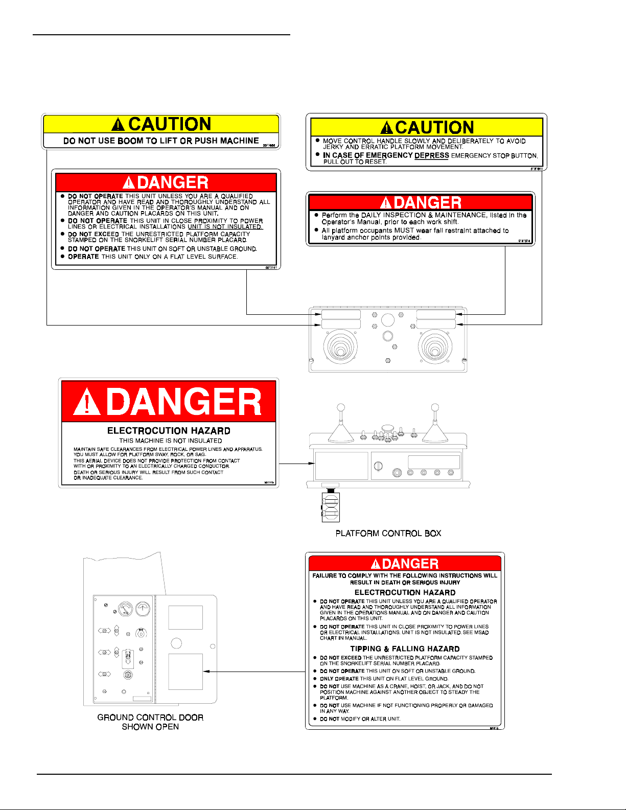
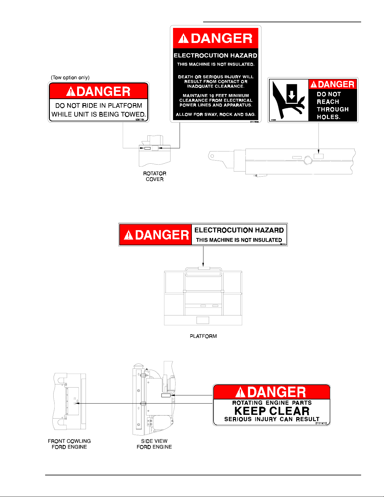
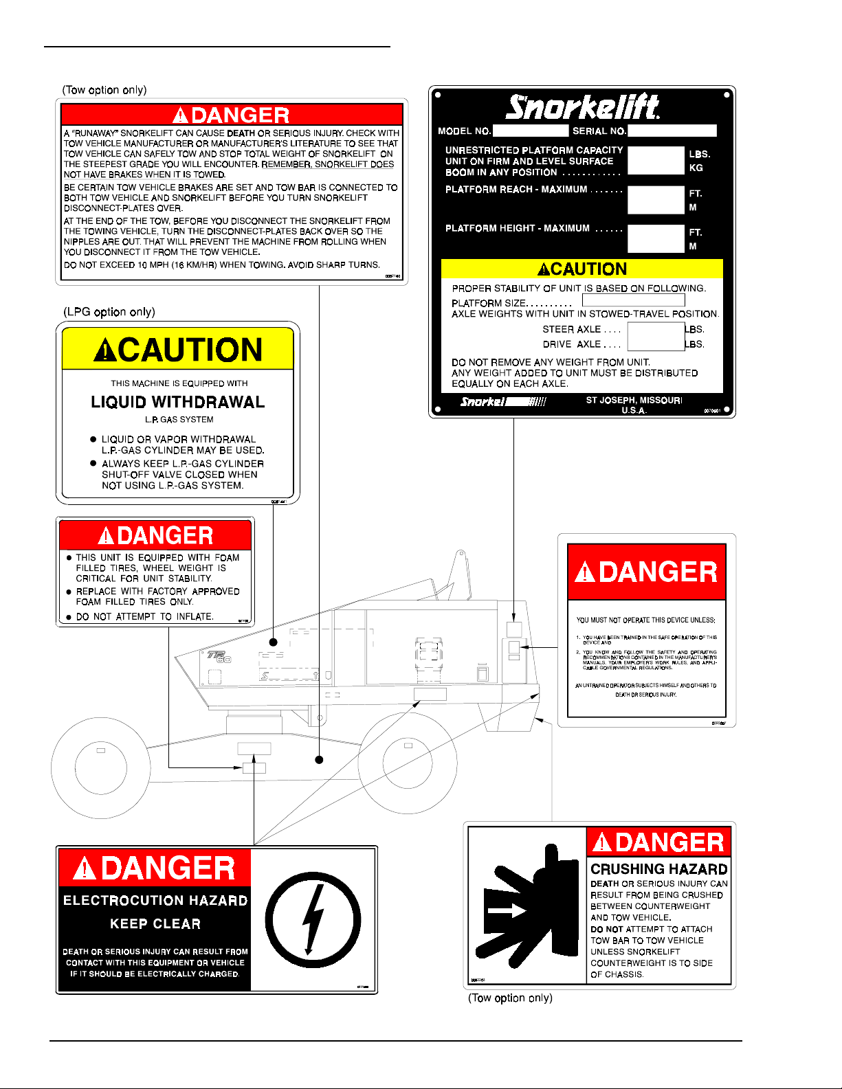
SAFETY DECALS & PLACARDS
There are several safety decals and placards on
the TB 60. Their locations and descriptions are
shown in this section. Take time to study them.
Be sure that all the safety decals and placards
on the TB 60 are legible. Clean or replace them if
you cannot read the words or see the pictures.
Clean with soap & water and a soft cloth. Do not
use solvents.
You must replace a decal or placard if it is
damaged, missing, or cannot be r ead. If it is on a
part that is replaced, make sur e a new decal or
placard is installed on the replaced part. See
your Snorkel dealer for new decals and placards.
Refer to PLACARDS AND DECALS
INSPECTION CHART and DRAWING in t he
“DAILY INSPECTION AND MAINT ENANCE”
chapter for part number s, locat ion, and r equired
quantities of all placards and decals.
P/N 0082168
1 - 3
1. SAFETY
Refer to PLACARDS AND DECALS INSPECTION CHART and DRAWING in the “DAILY
INSPECTION AND MAINTENANCE” chapter for part numbers, locations, and required
quantities of all placards and decals.
1 - 4
P/N 0082168
1. SAFETY
P/N 0082168
1 - 5
1. SAFETY
1 - 6
P/N 0082168
2. SAFETY DEVICES
2. SAFETY DEVICES
For emergency-operation controls and
procedures, see the “EMERGENCY
OPERATION” chapter in t his m anual.
The devices listed in this chapter are safety
devices. They are on a TB 60 to increase safety
in the work place for both the operat or and ot her
people near a TB 60. Do not by-pass, disable,
modify, or ignore any of these devices. Check
them carefully at the start of each work shift to
see that they are in working order (see “DAI LY
INSPECTION & MAINTENANCE” chapter) . I f
any is found to be defective, remove the TB 60
from service immediately until a q ualified service
technician can make repairs.
TILT ALARM & LEVEL SENSOR
There are two tilt alarm sirens on a TB 60.
When you are in control of a TB 60 and you hear
its two-toned siren, you should immediately:
1. Stop using the DRIVE controller st ick on
the platform-control box.
2. Completely retract and complet ely lower the
booms.
3. Use the platform-control box DRIVE
controller to move the TB 60 to a level surface
or more firm gr ound before extending or
raising the booms again.
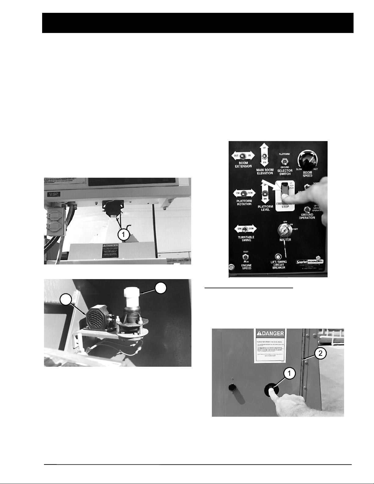
EMERGENCY STOP SWITCHES
One (1) is located under the platform-control box.
3
2
One (2) is located in the turntable next to t he
level sensor (3).
The sirens will both, simultaneously, emit a t wotoned sound (high-low-high-low...) if the TB 60 is
tilted more than 5° and the booms ar e not
completely retracted and completely down. Af t er
the sirens begin to sound, if t he t ilt continues to
increase, the TB 60 can turn over.
At the ground-control panel: Press the red
EMERGENCY STOP cover down, at any time,
under any conditions, and the entire machine
stops, the engine turns of f, the brakes set, and
nothing moves. This switch must be up for
anything on the TB 60 to work.
The ground-control panel EMERG ENCY STOP
switch (1) can also be used with the door (2)
closed.
P/N 0082168
2 - 1
2. SAFETY DEVICES
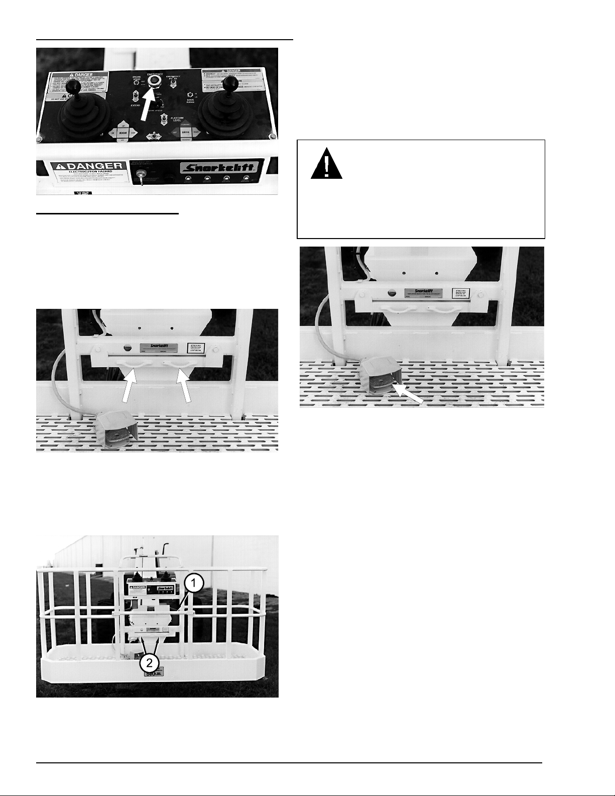
At the platform-control box: Press the large
red EMERGENCY STOP button down and the
entire machine stops, the engine tur ns off, the
brakes set, and nothing moves. This switch must
be pulled to its up (or out) position t o cont rol the
TB 60 from the platform.
LANYARD ANCHOR POINTS
leave the platform. Raise the gate and step
under it onto the platform . Once you have
entered the platform and at tached your fall
restraint lanyard to an anchor point (2), check to
see that the gravity gate (1) has fallen back into
place.
FOOT SWITCH
DANGER
Serious injury can result from sudden stops.
To avoid sudden stops, do not remove your
foot from the foot switch while t he TB 60 is in
motion.
All personnel on the platform should att ach t heir
fall restraint lanyards to one of the lanyard
anchor points.
GRAVITY GATE
The gravity gate (1) is the place in the platform
guardrail system where you should enter and
The foot switch prevents the platf or m from
moving if something accidentally pushes one of
the platform-moving controls on the platformcontrol box. (Stepping on the foot switch is an
action that must be performed, at the same time
as another action, to make the plat form move.)
2 - 2
P/N 0082168
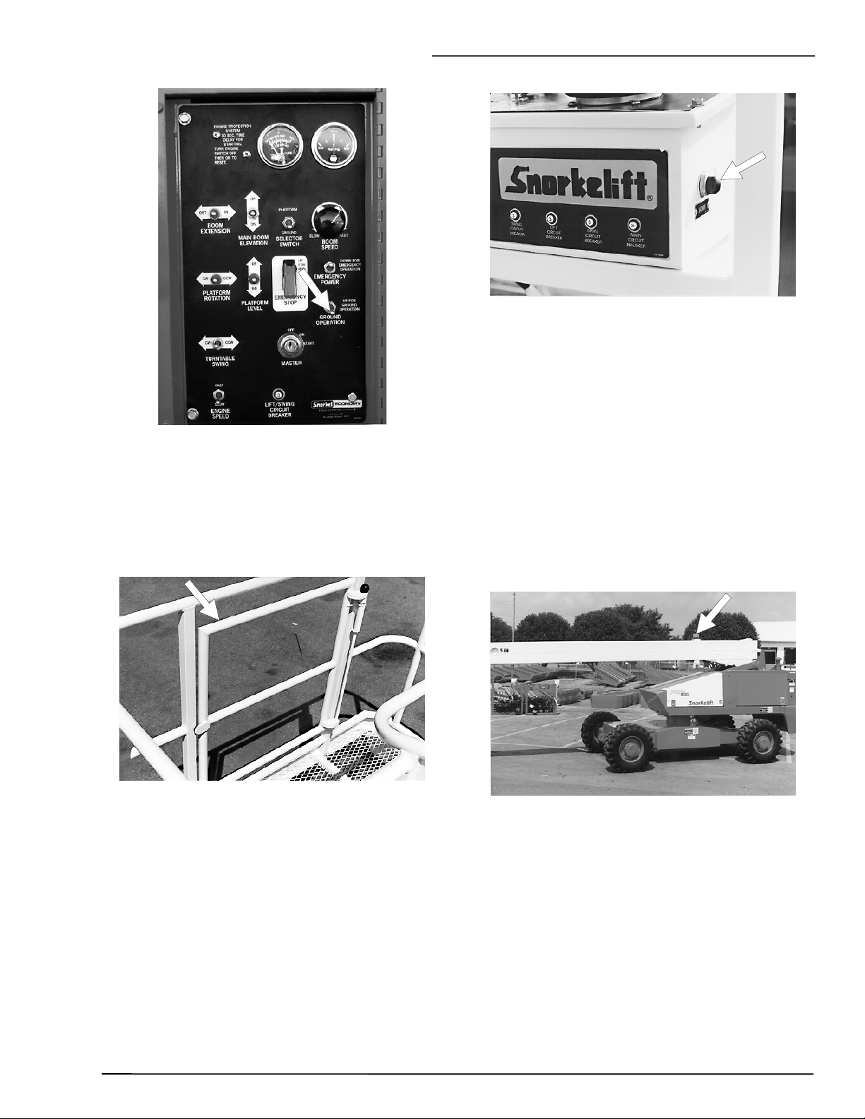
GROUND OPERATION SWITCH
2. SAFETY DEVICES
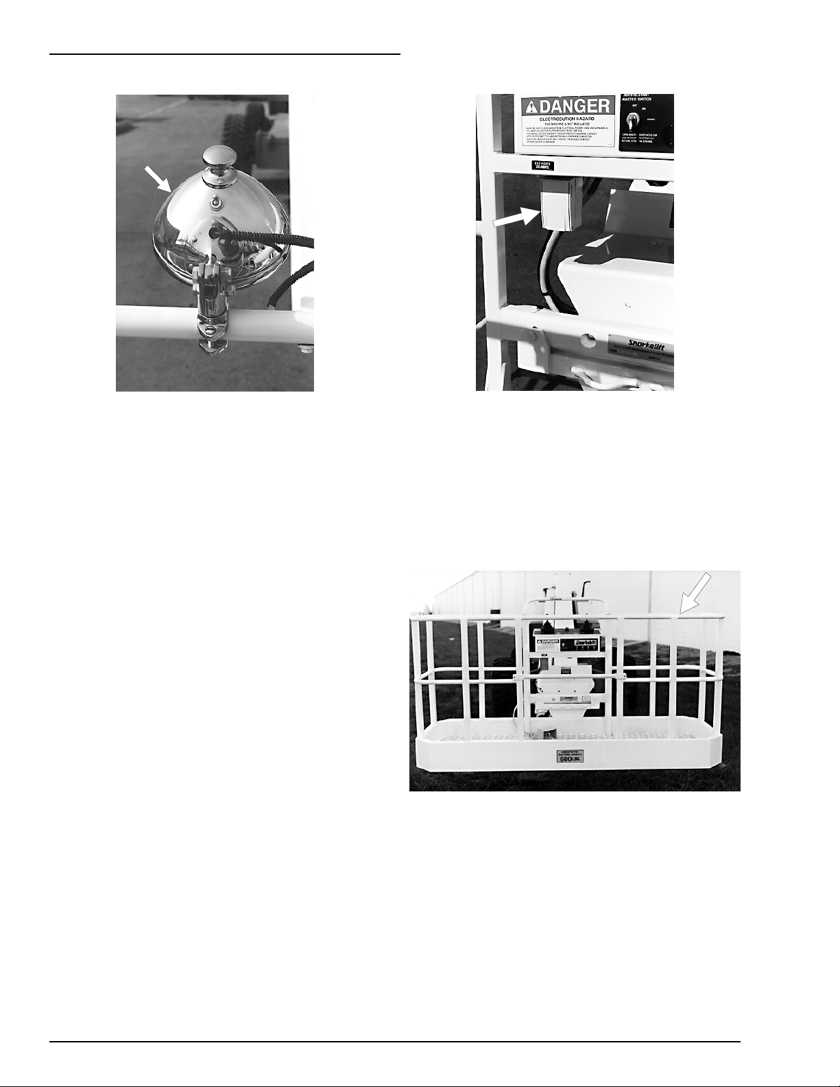
OPERATOR HORN (option)
GROUND OPERATION
The
platform fr om moving if something accident ally
pushes one of the platform-moving switches at
the ground-control panel. (I t is an action that
must be performed, at t he sam e time as another
action, to make the platform move.)
SELF-CLOSING GATE
switch prevents the
(option)
The operator
the platform-control box. It is used primarily to
get the attention of people on the ground when
you are working aloft. The horn itself is located
next to the level sensor, it is the same horn used
to sound the tilt alarm. For the horn to work the
BATTERY
switches, on the ground-control panel, must be
set as indicated:
SELECTOR SWITCH
EMERGENCY STOP
MASTER
FLASHING LIGHT (option)
HORN
switch must be ON and the following
..........................ON
button is on the right side of
.......PLATFORM
.......pulled out
The self-closing g ate is designed to automatically
close after you enter or leave the platf or m. It
helps prevent people from falling off the platfor m .
P/N 0082168
The flashing light alerts people that the TB 60 is
present. The light flashes at about one flash per
second anytime the
STOP
are all ON. There is no ON/OFF switch f or t he
flashing light.
(at the ground), and
BATTERY, EMERGENCY
MASTER
switches
2 - 3
2. SAFETY DEVICES
PLATFORM WORK LIGHTS
The platform work lig ht s are located on top the
platform guardrail. Use the lights to improve
visibility when you are working aloft in dimly lit
areas. Do not use the platform work lights to
drive on public thoroughfares.
(option)
GFCI OUTLET
The GFCI (ground fault circuit interrupt ) is
located under the platform-control box. The GFCI
protects against short circ uit s to ground. When
there is a short to ground the G FCI automatically
shuts off power the way a circuit breaker would.
(option)
For more informat ion about platform work light s
see the “OPTIONS” chapter .
DRIVING LIGHTS
Two 30 watt headlights are located on top of the
front cowling, two 25 watt blinking t aillights are
on the sides of the rear cowlings. Dr iving lights
help improve your visibility and help others see
you when you are driving on dimly lit work sites.
Driving lights are not f or driving on public
thoroughfares.
For more informat ion about dr iving lights see the
“OPTIONS” chapter .
MOTION WARNING ALARM
The motion warning alarm emits a loud beeping
sound at ground level anytime the
DRIVE/STEER
REVERSE. This alarm alerts people on t he
ground that the TB 60 is traveling along the
ground. The alarm it self is below the wiring box,
inside the front-right side of the turntable.
controller is in FORWARD or
(option)
(option)
For more information about t he GFCI see the
“OPTIONS” chapter .
GUARDRAILS
The guardrails help protect you f r om falling off
the platform. Be sure t he guardrails are properly
installed and that the gate is in place.
2 - 4
P/N 0082168

3. SPECIFICATIONS
3. SPECIFICATIONS
The Snorkelift TB 60 is a boom-supported
elevating work-platform built to conform t o th e
following standards:
OSHA Paragraph 1910.67 Title 29, C.F.R.
Vehicle-Mounted Elevating and Rotating Work
Platforms - Labor.
OSHA Paragraph 1926.556 Title 29, C.F.R Aerial
Lifts - Construction.
ANSI Standard A92.5, Boom-Supported
Elevating Work Platforms.
CSA Standard CAN3-B354.4-M82, Boom-type
Elevating Work Platforms.
GENERAL SPECIFICATIONS
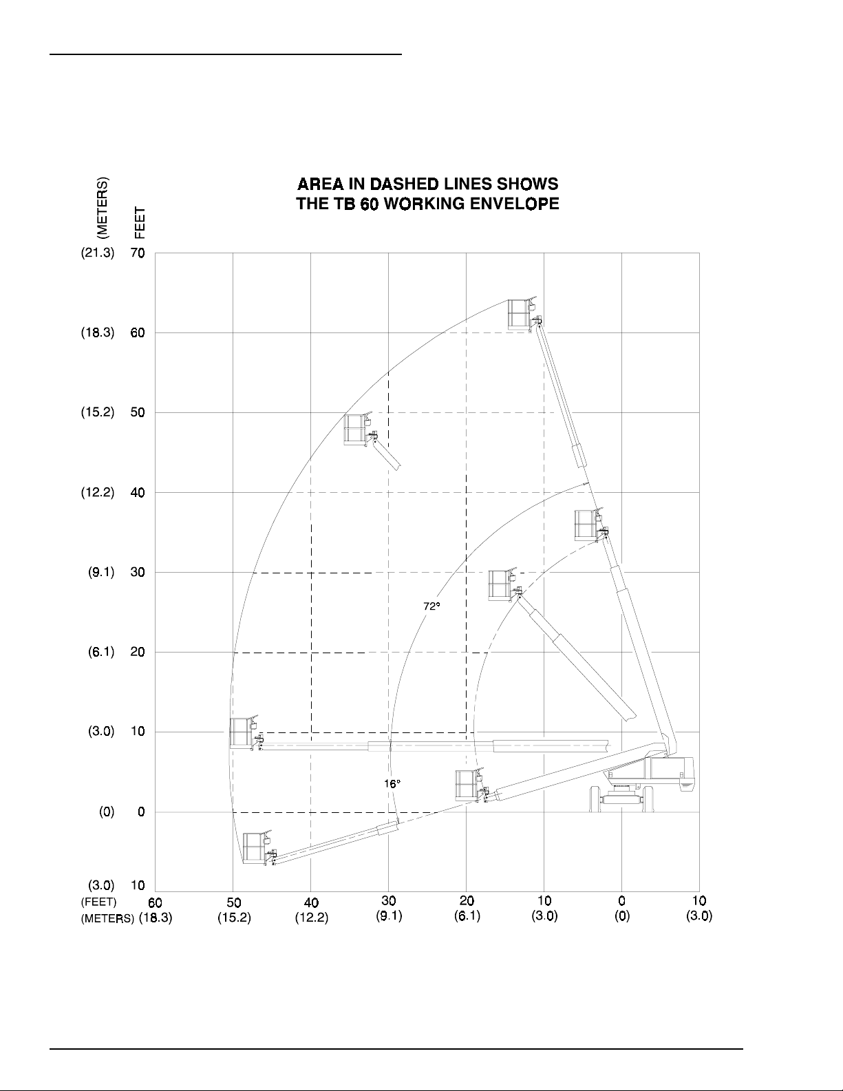
Working height (nominal) ...... 66 ft - 0 in (20.1 m)
Platform height (maximum) ... 60 ft - 0 in (18.3 m)
Platform rea ch (maximum).... 50 ft - 0 in (15.2 m)
Length
(
booms down and retracted
Width...................................... 8 ft - 0.5 in (2.5 m)
Height
(booms down and retraced) .... 8 ft - 9 in (2.7 m)
Wheelbase.............................. 10 ft - 0 in (3.0 m)
Ground clearance........................... 13 in (33 cm)
Weight (approximate)......... 20,700 lbs (9,389 kg)
Ground pressure, max............... 64 psi (442 kPa)
Wheel lo a d, max . sing le........10,600 lbs (4,808 kg)
Boom elevation.................+72°/-16° to horizontal
Gradeability .................................................. 25%
Travel speeds:
booms down and retracted .. 3.0 mph ( 4.8 km/hr)
booms up and/or extended.... 1 mph (1.6 km/hr)
) .. 30 ft - 10 in (9.4 m)
Turning radius, inside................ 15 ft 5 in (4.7 m)
Tires......................... 15 x 19 .5 in (3 8 X 5 0 c m) , 1 2 ply
Electrical system.. 12 V dc (neg. chassis ground)
Environmental operating ranges:
ambient air temperature.............. 0°F to +110°F
................................................. (-18°C to +43° C)
wind speed (maximum gust
or continuous)...................... 28 mph (45 km/hr)
Fuel tank capacity:
standard gasoline
or diesel........................ 40 gal USA (151 liters)
optional LPG.................... 43.5 lbs USA (20 kg)
optional gasoline or diesel
(Used when LPG cylinder is mounted
inside the turntable, in front of the
gasoline or diesel tank.) ... 20 gal USA (76 liters)
Hydraulic oil tank capaci ty.. 26.1 gal USA (99 liters)
Maximum hydraulic oil temperature
(at tank) ....................................... 200°F (93°C)
Hydraulic oil system
capacity ........................ 35 gal USA (132 liters)
Hydraulic oil and grade
Above 10°F (-13°C)Mobil DTE-13M (ISO VG32)
Below 10°F (-13°C) Mobil DTE-11M (ISO VG15)
Hydraulic system
maximum pressure ....... 2,500 psi (17,250 kPa)
Boom movement times
(complete range of movement):
Turntable Swing
CW or CCW (360°): ............... 85 - 95 seconds
Platform Rotation
CW or CCW (180°): ............... 16 - 20 seconds
Main Boom Elevation
UP:......................................... 40 - 45 seconds
DOWN:.................................. 40 - 45 seconds
Boom Extension
OUT:...................................... 60 - 70 seconds
IN:.......................................... 50 - 60 seconds
PLATFORM SPECIFICATIONS
SIZE
PLATFORM
standard steel 30 x 60 (76 x 152)
optional steel 30 x 92 (76 x 233)
optional aluminum 30 x 60 (76 x 152)
optional aluminum 30 x 92 (76 x 233)
P/N 0082168
inches (cm)
Unrestricted rated work load (total weight of personnel,
tools, and materials that the platform is designed to carry
above its floor -- same as UNRESTRICTED PLATFORM
CAPACITY)
Rated work load: 500 lbs (227 kg)
Rated number of occupants: 2 people
Rated work load: 500 lbs (227 kg)
Rated number of occupants: 2 people
Rated work load: 660 lbs (300 kg)
Rated number of occupants: 2 people
Rated work load: 600 lbs (273 kg)
Rated number of occupants: 2 people
3 - 1
3. SPECIFICATIONS
ENGINE DATA
ENGINE MAKE DEUTZ FORD (gasoline) FORD (LPG)
MODEL F4L-1011F LRG-423
COOLANT air 50% water + 50% ethylene glycol
FUEL
FUEL GRADE
diesel
DIN 51 601.
BS 2869: A1 and A2.
ASTM D 975-81:
1-D and 2-D.
W-F-800C: DF-A,
DF-1, and DF-2.
gasoline
leaded or unleaded
83 octane
(motor method).
LPG (liquefied
petroleum gas)
HD5
Gas Processors
Association
Standard 2140.
Category: special
duty propane.
OPERATING TEMPERATURE
OIL SUMP CAPACITY 10.5 qt USA
OIL FILTER CAPACITY
OIL GRADE
OIL WEIGHT see chart below see chart below
RUNNING TIME
(one tank fuel)
ENGINE OIL CHARTS
172°F - 203°F
(78°C - 95°C)
(10 liters)
0.5 qt USA
(0.5 liters)
API: CC/SE CC/SF
CD/SE CD/SF
CE/SF CE/SG
Any tank of fuel (regardless of whether it is LPG, gasoline, or
diesel) will last an entire eight hour shift, under normal working
conditions.
160°F - 190°F
(71°C - 88°C)
4 qt USA
(3.8 liters)
1 qt USA
(0.95 liters)
API: SH or SG
3 - 2
P/N 0082168
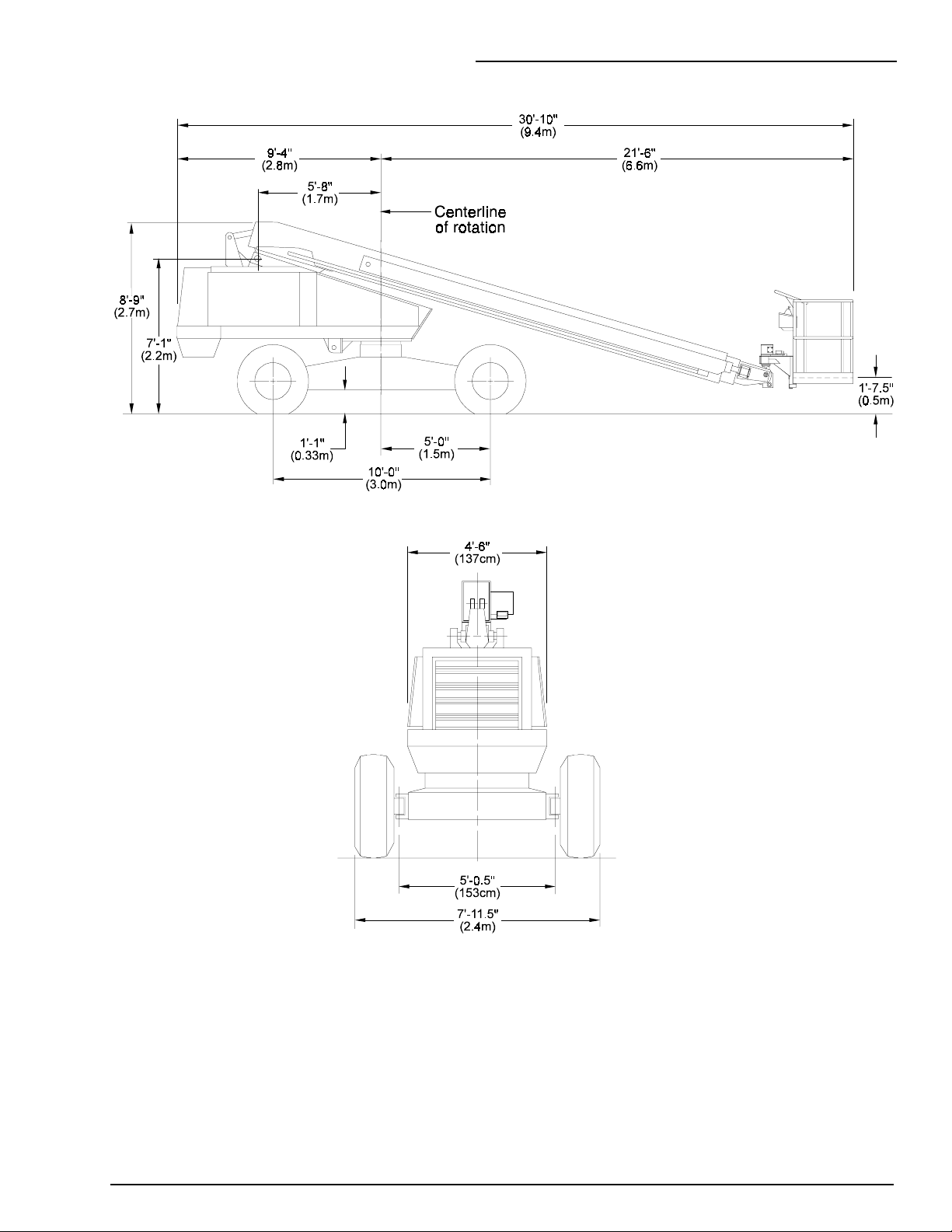
OVERALL DIMENSIONS
3. SPECIFICATIONS
P/N 0082168
3 - 3
3. SPECIFICATIONS
WORKING ENVELOPE
3 - 4
P/N 0082168

3. SPECIFICATIONS
3
)
SERIAL-NUMBER LOCATIONS
Serial Numbers are located in five places.
1. Above the ground-control panel on a placard.
(The last four digits are month and year shipped.)
2. On the back-right of the counterweight.
CHASSIS NOMENCLATURE
3. Above the lanyard anchor points on a placard.
(Last four digits are mo. and yr. shipped.)
TURNTABLE AND BOOM
NOMENCLATURE
4. Below the drain hole in the turntable.
5. At the weld on the rear of the chassis. (Fourwheel drive machines have the serial number
stamped on top the chassis just behind the
rotation-bearing turret.)
P/N 0082168
NOTE: If the turntable is rotated 180° its
FRONT is above the REAR of the chassis.
- 5 (3 - 6 blank
3 - 5

4. GAUGES & CIRCUIT BREAKERS
4. GAUGES & CIRCUIT BREAKERS
GAUGES
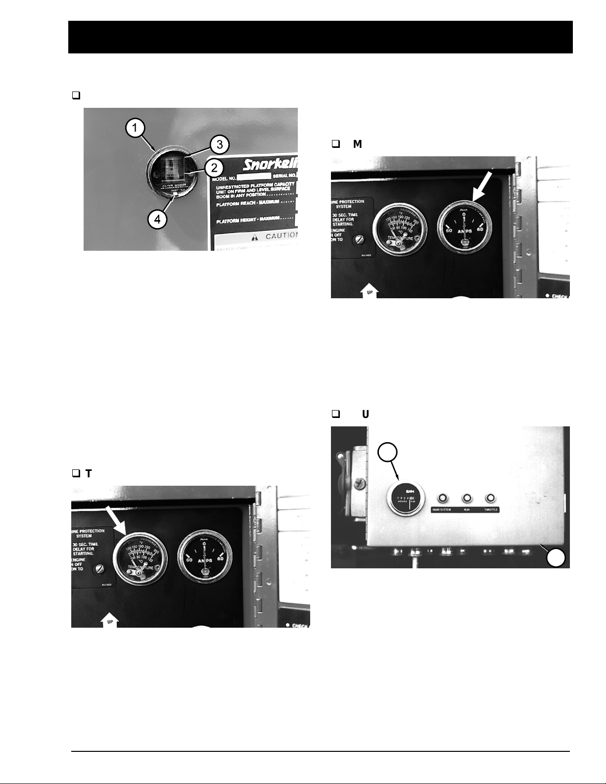
FILTER MINDER
The air filter g auge (1) (FILTER MINDER) is
located just above the ground-control panel. The
gauge measures the vacuum (air pressur e)
between the intake manifold and t he air filter. As
the filter clogs, t he vacuum increases (pressure
drops). As the vacuum increases, the yellow
indicator disk (2) raises toward the red ar ea ( 3)
of the sight glass. When the yellow disk reaches
the red, it’s time to chang e the air filter.
The indicator disk (2) stays at it s highest setting,
it does not go to the bottom of the sight glass
when the engine is turned off. After the f ilt er is
changed, press the small RESET button (4) t o
reset the indicator disk to the bottom of the sight
glass.
The TEMPERATURE gauge for Deutz engines
shows the temperature of the engine oil as the oil
leaves the oil filter. The t ypical operat ingtemperature range for a Deutz engine is 172°F to
203°F (78°C to 95°C).
AMPS
The AMPS gauge shows the electric current
from the alternator t o the battery(ies). When the
engine is running, the needle in the AMPS gauge
should not be to the left of “ 0. ” Under normal
operating conditions, after the engine has been
running for a few minutes, this gauge should
read “0.”
HOURS
1
TEMPERATURE
The TEMPERATURE gauge is located at the top
of the ground-control panel. For Ford engines it
shows the temperature of the water-ant ifreeze
mixture in the engine block. The t ypical
operating-temperatur e r ange for Ford engines is
160°F to 190°F (71°C to 88°C).
P/N 0082168
2
The HOURS gauge (1) is located on the wiring
box (2), to the left of the ground-control panel
(behind the cowling door). The HOURS gauge is
basically an electric clock. It accumulates tim e
when the BATTERY, EMERGENCY STOP (at
the ground), and MASTER switches are all in the
ON position. The HOURS g auge cannot be
reset. Use it to tell when it is time for 150 hour or
500 hour maintenance.
4 - 1
4. GAUGES & CIRCUIT BREAKERS
Fuel
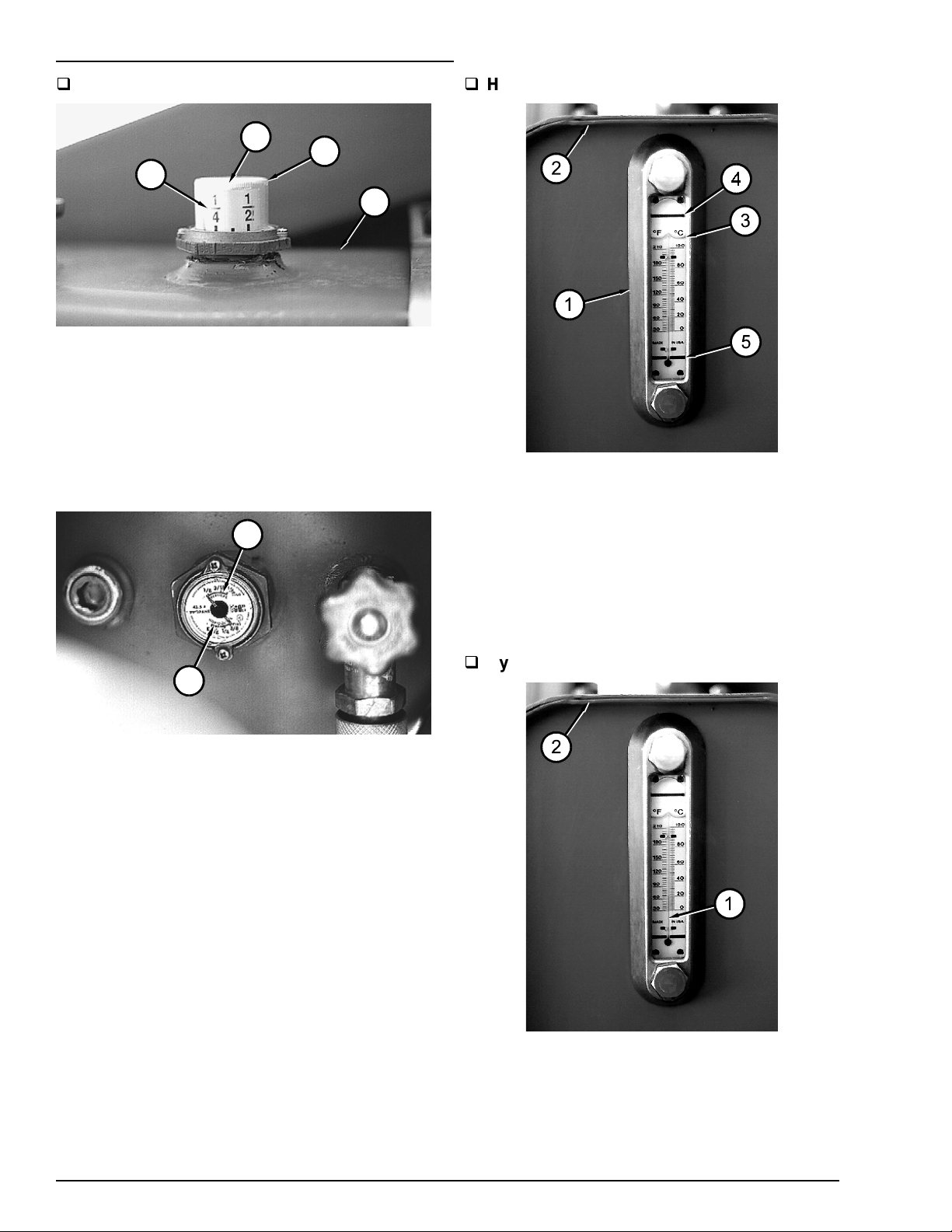
Hydraulic Oil Level
3
1
4
2
The fuel gauge (1) is locat ed on top of the
gasoline or diesel fuel tank (2). Read it at the line
(3) in the clear plastic window (4). It reads in
fractions-of-a- full-tank. The tank shown is a little
less than 3/8 full.
NOTE: Do not run a diesel fuel tank dry. Air in
the fuel line makes a diesel engine hard to
start.
1
The hydraulic-oil level gauge (1) is on the end of
the hydraulic oil tank (2). It shows the actual level
of oil inside the tank. Read it only when the
booms are completely down and completely
retracted. Otherwise, the lift and/or extend
cylinders become large reservoirs for hydraulic
oil and the oil level in the tank will be low. The oil
level (3) should be between the HIGH mark (4)
and LOW mark (5).
2
(OPTION - LPG) LPG t anks have two fuel
gauges (1) (2) on top. One measures correctly
when the tank is standing on end (VERTICAL)
the other measures correctly when the tank is
laying down (HORIZONTAL). Both read in
fractions-of-a- full-tank. Tanks on TB 60’s are
mounted horizontally. Therefore, you should read
the HORIZONTAL scale (2). This one is over 3/8
full.
Hydraulic Oil Temperature
The hydraulic-oil temperature gauge (1) is
located inside the hydraulic-oil level gauge. It
measures the temperature of the oil in the tank
(2). The temperatur e should not exceed 200°F
(93°C). If it does, r educe your dr iving speed or
stop the TB 60 to let the hydraulic oil cool.
4 - 2
P/N 0082168
 Loading...