


X33RT
Operator Manual
This first section of the Operator manual is the English language version.
Betriebsanleitung
Im zweiten Abschnitt dieser Betriebsanleitung finden Sie die Deutsche Version.
Manuel Utilisateur
La troisième section de ce manuel est la version en langue Française.
Manual del Usuario
El apartado cuarto de este manual del usuario corresponde a la versión en Español.
Manuale d’Uso
La quinta sezione di questo manuale d'uso è la versione in lingua Italiana.
Bedieningshandleiding
Het zesde deel van de Bedieningshandleiding is de Engelstalige versie.
(EN) Manual part number 508401-001 for serial numbers 70810 to current.
(DE) Bestellnummer 508401-001 ab Seriennummer 70810 fortlaufend.
(FR) Manuel Pièce numéro 508401-001 pour numéro série 70810 jusqu'au
numéro courant.
(ES) El número de referencia para el manual es el 508401-001 para los
números de serie del 70810 hasta el actual.
(IT) Manuale Ricambi Numero 508401-001 per Numeri di Serie da 70810
all’attuale.
(NL) Handboek onderdeelnummer 508401-001 voor de serienummers van
70810 tot de huidige.
Jan 08

X-27-33-RT
Serial N umbers NZ 70810 - C urrent
ENGLISH
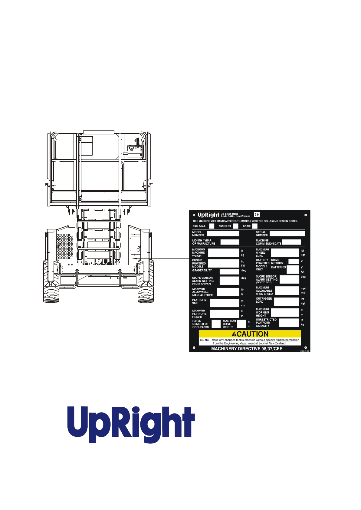
When con tact ing UpRight for ser vice or parts in formation, be sure to in clude the MODEL and SERIAL
NUMBERS from the equip ment name plate.
POWERED ACCESS
www.upright.com
Up Right Pow ered Ac cess HQ
Vigo Cen tre
Birtley Road
Wash ing ton
Tyne & Wear
NE38 9DA
Tel: +44 (0) 845 1550 057
Fax: +44 (0) 845 1557 756

OPERATION MANUAL
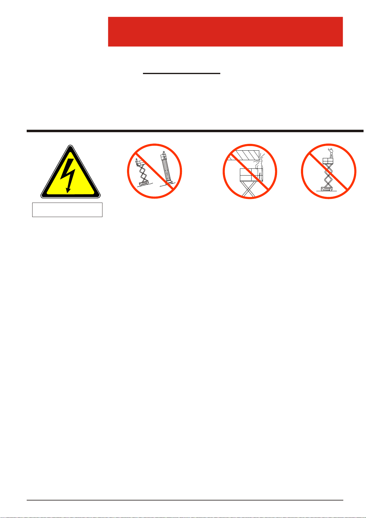
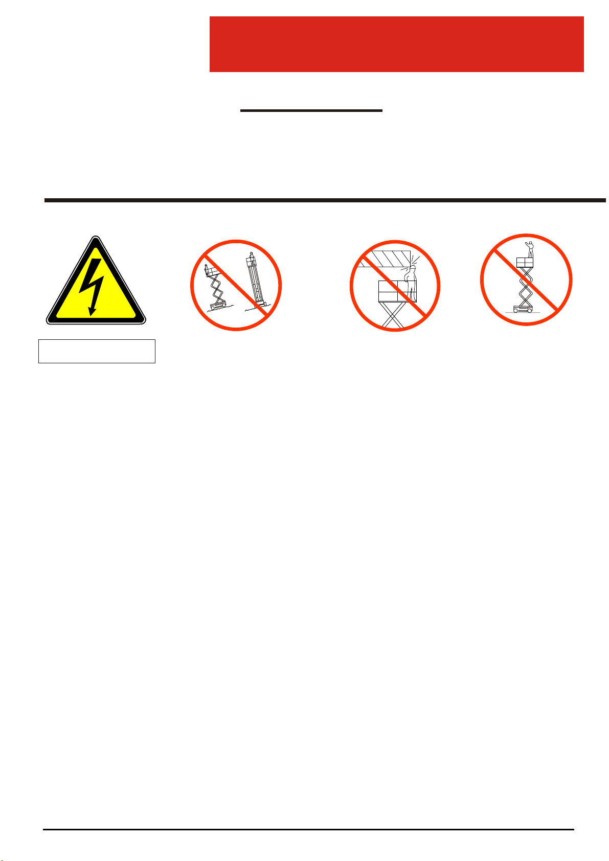
Electrocution Hazard
Tip Over Hazard
Collision Hazard
Fall Hazard
This machine is not
insulated
NEVER elevate the platform or drive
the machine while elevated unless
the machine is on a firm, level surface
NEVER position the platform
without first checking for overhead
obstructions or other hazards
NEVER climb, stand or sit on
platform guardrails or midrail
WARNING
All per son nel shall care fully read, un der stand and fol low all safety rules and op er at ing
in struc tions be fore op er at ing or per form ing main te nance on any Up Right ae rial work plat form.
Safety Rules
USE OF THE AERIAL WORK PLATFORM: This ae rial work plat form is in tended to lift peo ple and their tools as well as the ma te rial
used for the job. It is de signed for re pair and as sem bly jobs and as sign ments at over head workplaces (ceil ings, cranes, roof struc tures, build ings etc.). All other uses of the ae rial work plat form are pro hib ited!
THIS AERIAL WORK PLATFORM IS NOT INSULATED! For this rea son it is im per a tive to keep a safe dis tance from live parts of
elec tri cal equip ment!
Ex ceed ing the spec i fied per mis si ble max i mum load is pro hib ited! See "Spe cial Lim i ta tions" on page 4 for de tails.
The use and op er a tion of the ae rial work plat form as a lift ing tool or a crane (lift ing of loads from be low up wards or from up high on
down) is pro hib ited!
NEVER ex ceed the man ual force al lowed for this ma chine. See "Spe cial Lim i ta tions" on page 4 for de tails.
DISTRIBUTE all plat form loads evenly on the plat form.
NEVER op er ate the ma chine with out first sur vey ing the work area for sur face haz ards such as holes, drop-offs, bumps, curbs, or de -
bris; and avoid ing them.
OPERATE ma chine only on sur faces ca pa ble of sup port ing wheel loads.
NEVER op er ate the ma chine when wind speeds ex ceed this ma chine's wind rat ing. See "Beau fort Scale" on page 4 for de tails.
IN CASE OF EMERGENCY push EMERGENCY STOP switch to de ac ti vate all pow ered func tions.
IF ALARM SOUNDS while the plat form is el e vated, STOP, care fully lower the plat form. Move ma chine to a firm level sur face.
Climb ing up the rail ing of the plat form, stand ing on or step ping from the plat form onto build ings, steel or pre fab con crete struc tures,
etc., is pro hib ited!
Dis man tling the swing gate or other rail ing com po nents is pro hib ited! Al ways make cer tain that the swing gate is closed and se curely locked!
It is pro hib ited to keep the swing gate in an open po si tion (held open with tie straps) when the plat form is raised!
To ex tend the height or range by plac ing lad ders, scaf folds or sim i lar de vices on the plat form is pro hib ited!
NEVER per form ser vice on the ma chine while the plat form is el e vated with out block ing the el e vat ing as sem bly.
INSPECT the ma chine thor oughly for cracked welds, loose or miss ing hard ware, hy drau lic leaks, loose wire con nec tions, and dam -
aged ca bles or hoses be fore us ing.
VERIFY that all la bels are in place and leg i ble be fore us ing.
NEVER use a ma chine that is dam aged, not func tion ing prop erly, or has dam aged or miss ing la bels.
To by pass any safety equip ment is pro hib ited and pres ents a dan ger for the per sons on the ae rial work plat form and in its work ing
range.
NEVER charge bat ter ies near sparks or open flame. Charg ing bat ter ies emit ex plo sive hy dro gen gas.
Mod i fi ca tions to the ae rial work plat form are pro hib ited or per mis si ble only at the ap proval by UpRight.
AFTER USE, se cure the work plat form from un au tho rized use by turn ing the keyswitch off and re mov ing the key.
Operation Manual Page 1

Introduction .........................................................3
CONTENTS
General Description...................................................3
Platform Capacity ...................................................4
Manual Force ......................................................4
Beaufort Scale .....................................................4
Lift Overload Alarm..................................................4
Controls and Indicators ...............................................5
Pre-Operational Safety Inspection.......................................6
System Function Inspection............................................7
Operation ...........................................................8
Platform Extension ..................................................8
Travel With The Platform Lowered......................................8
Steering...........................................................8
Elevating The Platform ...............................................8
Travel With The Platform Elevated .....................................9
Lowering The Platform ...............................................9
Levelling The Platform ...............................................9
Emergency Lowering ...............................................10
Fold Down Guardrails...............................................11
Fold Down Procedure..........................................11
Erection Procedure............................................11
Towing or Winching .................................................12
Parking Brake Release..............................................12
After Use Each Day ................................................12
Hour Meter .......................................................12
Transporting The Work Platform .......................................13
Preparation For Shipment ...........................................13
Lifting By Crane ...................................................13
By Forklift ........................................................13
Driving or Winching Onto a Truck .....................................13
Maintenance ........................................................14
Blocking The Elevating Assembly .....................................14
Scissor Brace Installation.......................................14
Scissor Brace Stowage ........................................14
Battery Maintenance................................................15
Battery Charging .............................................15
Inspection and Maintenance Schedule ............................16
Daily Preventative Maintenance Checklist ...............................16
Labels .............................................................18
Specifications.......................................................19
Page 2 Operation Manual

Introduction
INTRODUCTION
GENERAL DESCRIPTION
1
3
5
7
2
4
6
8
W A R N I N G
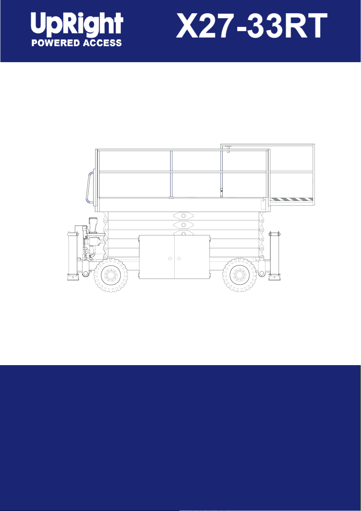
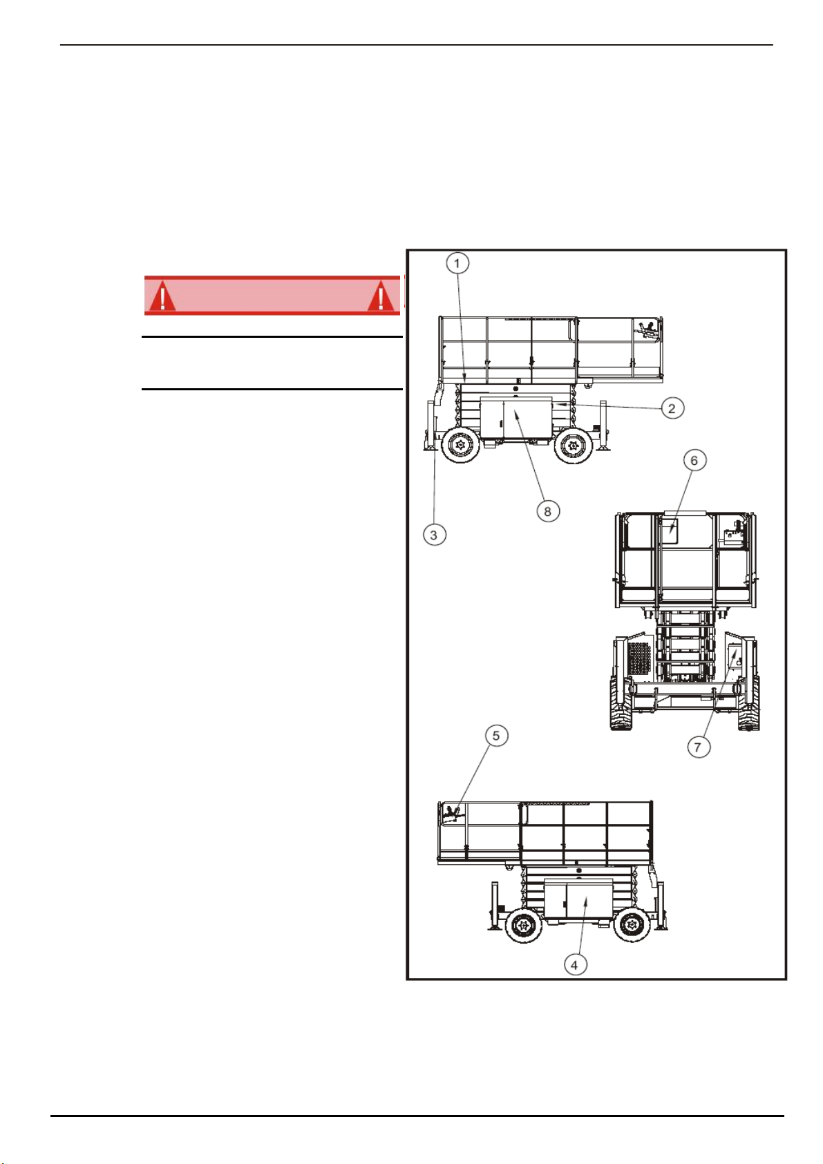
This man ual cov ers op er a tion of the X-27-33-RT Se ries Self-Pro pelled Rough Ter rain
Work Plat forms. This man ual must be stored on the ma chine at all times.
1. Platform
DO NOT use the main te nance plat form
with out guard rails prop erly as sem bled
and in place
Figure 1
2. Elevating Assembly
3. Chassis
4. Engine
5. Platform Controls
6. Manual Case
7. Chassis Controls
8. Hydraulic Fluid Reservoir
Operation Manual Page 3
Special Limitations
SPECIAL LIMITATIONS
D A N G E R
PLATFORM CAPACITY
D A N G E R
MANUAL FORCE
D A N G E R
BEAUFORT SCALE
BEAUFORT
SCALE
WIND SPEED
GROUND CONDITIONS
m/s km/h ft/s mph
3 3.4~5.4 12.5~19.4 11.5~17.75 5~12.0 Papers and thin branches move, flags wave.
4 5.4~8.0 19.4~28.8 17.75~26.25 12.0~18 Dust is raised, paper whirls up, and small
5 8.0~10.8 28.8~38.9 26.25~35.5 18~24.25 Shrubs with leaves start swaying. Wave crests are
6 10.8~13.9 38.9~50.0 35.5~45.5 24.5~31 Tree branches move. Power lines whistle. It is
7 13.9~17.2 50.0~61.9 45.5~56.5 31~38.5 Whole trees sway. It is difficult to walk against the
branches sway.
apparent in ponds or swamps.
difficult to open an umbrella.
wind.
LIFT OVERLOAD ALARM
D A N G E R
Travel with the plat form raised is lim ited to creep speed range.
El e vat ing the Work Plat form is lim ited to firm, level sur faces only.
The el e vat ing func tion shall ONLY be used when the work plat form is lev eled and on a firm sur face.
The max i mum ca pac ity for the MACHINE, in clud ing oc cu pants is de ter mined by model and op tions, and is listed in "Spec i fi ca tions" on page 19.
DO NOT ex ceed the max i mum plat form ca pac ity or the plat form oc cu pancy lim its for this ma chine.
Man ual force is the force ap plied by the oc cu pants to ob jects such as walls or other struc tures out side the work plat form.
The max i mum al low able man ual force is lim ited to 200 N (45 lbs.) of force per oc cu pant, with a
max i mum of 400 N (90 lbs.) for two or more oc cu pants.
DO NOT ex ceed the max i mum amount of man ual force for this ma chine.
Never op er ate the ma chine when wind speeds ex ceed 25 km/h (15 mph) [Beau fort scale 4].
Page 4 Operation Manual
If a load which is greater than the safe work ing load is pres ent in the bas ket all ma chine func tions
will cease to op er ate and an acous tic warn ing will sound. In or der to re turn to nor mal op er a tion a
load equal to or less than the safe work ing load must be pres ent in the bas ket.
Never op er ate the ma chine with a plat form load greater than the rated ca pac ity.

Contro ls and Indi cato rs
C
ON T R OL S A ND
I
NDI C AT OR S
9
9
3
3
11
11
5
5
13
7
7
15
2
2
10
10
4
4
12
12
12
12
12
6
6
14
8
8
16
1
1
Emergency S top Switch
Emergency S top Switch
1.
1.
S tart Switch
S tart Switch
2.
2.
Glow Plug/Choke
Glow Plug/Choke Indicator Light
3.
3.
Glow Plug/Choke Indicator Light
Glow Plug/Choke
4.
4.
Safety Control
Lift Indicator Light
5.
5.
Joystick Controller
Plat form Lif t/Lower Switch
6.
6.
S teering Rocker Switch
Fuel Selector Switch (When Option Fitted)
7.
7.
Lift/Drive Selector
Ground/Plat form Selector
8.
8.
S peed Selector
Contact Breaker
9.
9.
Lift Indicator Light
Hour Meter
10.
10.
Drive Indicator Light
Water T emperature Gauge
11.
11.
Manual S tabiliser Switches
Ammeter Gauge
12.
12.
Auto Level / Auto S tow Switch13.
Horn Switch14.
Oil Pressure W arning Light15.
Plat form Overload Indicator Light
PLA TFORM CONTROLS
16.
GROUND/CHASSIS CONTROLS
Figure 2: Contr ols and Indic ators
Opera tion Manua l Page 5

Pre-Operation Safety Inspection
PRE-OPERATIONAL SAFETY INSPECTION
NOTE: Care fully read, un der stand and fol low all safety rules, op er at ing in struc tions, la bels
and Na tional safety In struc tions/Re quire ments. per form the fol low ing steps each day be fore use.
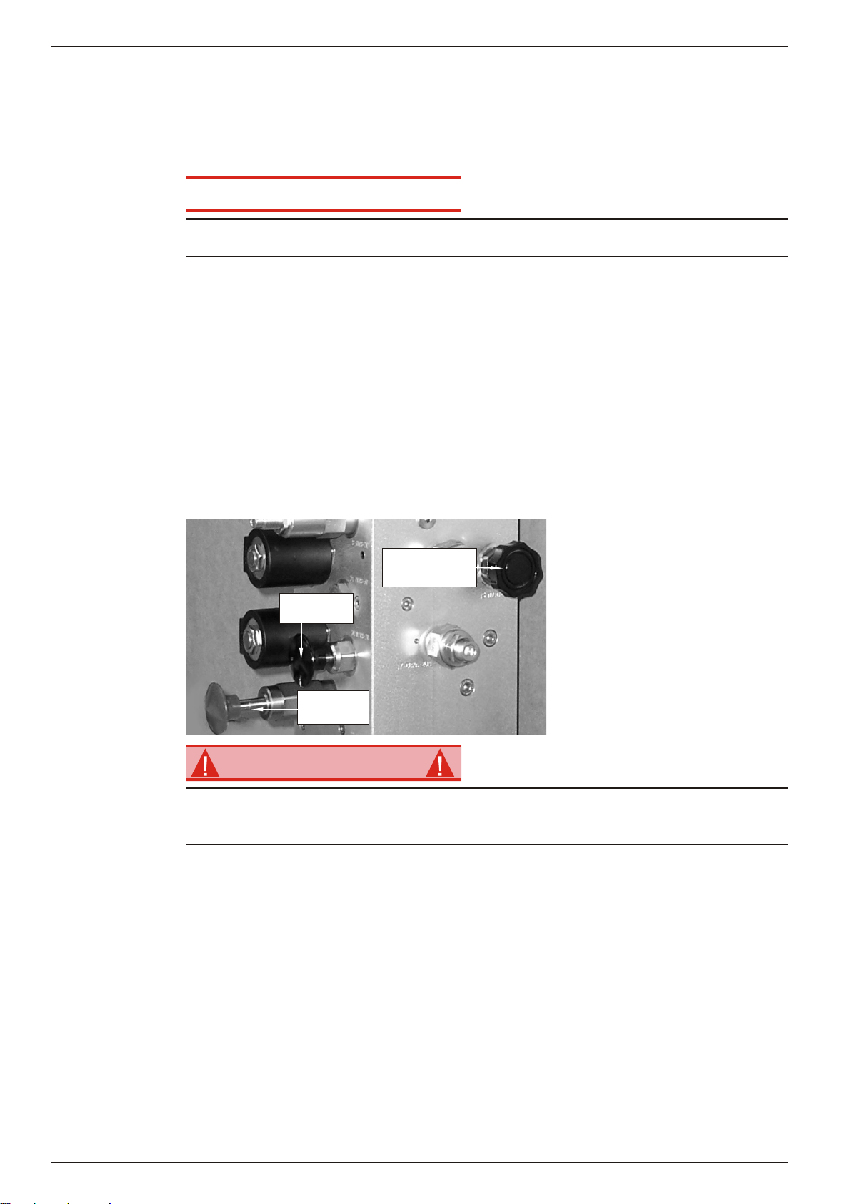
1. Open cabinets and inspect for
damage, fluid leaks or missing
parts.
Figure 3: Hydraulic Tank
2. Check the level of the hydraulic
fluid with the platform fully
lowered. The hydraulic reservoir is
located in the Control Cabinet.
The fluid must be above the
minimum line. Add hydraulic fluid
if necessary.
3. Check the fluid level in the starter
battery is correct.
4. Check the level of the Diesel fuel
with the engine switched off. The fuel tank is located in the Engine Cabinet. Add fuel as
required.
5. Check that all the guardrails are in place and all the fasteners are properly tightened.
6. Inspect the machine thoroughly for cracked welds and structural damage, loose or missing
hardware, hydraulic leaks, damaged control cable, loose wire connections and wheel bolts.
Page 6 Operation Manual

System Function Inspection
SYSTEM FUNCTION INSPECTION
W A R N I N G
Re fer to Fig ure 2 (Page 5) for the lo ca tions of var i ous con trols and in di ca tors.
STAND CLEAR of the work plat form while per form ing the fol low ing checks.
Be fore op er at ing the work plat form, sur vey the work area for sur face haz ards such as holes,
drop-offs, bumps and de bris.
Check in ALL di rec tions, in clud ing above the work plat form, for ob struc tions and elec tri cal con duc tors.
1. Move the machine, if necessary, to an unobstructed and level area to allow for full elevation.
2. Pull Chassis Emergency Stop Switch to the ON position.
3. Pull Platform Emergency Stop Switch to the ON position.
4. Visually inspect the elevating assembly, lift cylinder, cables, and hoses for cracked welds and
structural damage, loose hardware, hydraulic leaks, loose wire connections, and erratic
operation. Check for missing or loose parts.
5. Turn the key on and start the engine.
6. Select GROUND operation on the platform/ground switch.
7. Hold the platform LIFT/LOWER switch up to the rise position and fully elevate the platform.
8. Partially lower the platform by pushing the platform lift/lower switch down and check for
proper operation of the audible lowering alarm.
9. Pull the Emergency Lowering control to check for proper operation. When the platform is
lowered, release the knob.
10. Push the chassis Emergency Stop Switch to check for proper operation. All machine
functions should be disabled. Pull the Emergency Stop Switch to allow normal operation to
resume.
11. Check that the route is clear of obstacles (persons, obstructions, holes, and drop-offs, bumps
and debris), is level, and is capable of supporting the wheel loads.
12. Mount the platform and properly close the entrance gate.
13. Check the operation of the stabilisers. Use the AUTO LEVEL switch to set the stabilisers and
ensure that the LIFT ENABLE LIGHT comes on. Select AUTO STOW to fully retract the
stabilisers.
14. Check the operation of the stabilisers in MANUAL MODE. Operate each of the individual
Stabiliser Switches to see that they both extend and retract individual stabilisers.
15. Select DRIVE mode.
NOTE: Use both HI and LOW drive when per form ing the fol low ing step.
16. While engaging the Interlock Switch, move the Control Handle to FORWARD, then
REVERSE, to check for speed control
17. Push the Steering Switch RIGHT, then LEFT, to check for steering control.
18. Select LIFT mode. Grasp the Control Handle, engaging the Interlock Switch, and pull it back
to check platform lift controls. Raise the platform to full elevation.
19. Push forward on the Control Handle. The platform should descend and the audible lowering
alarm should sound.
20. Push the Platform Emergency Stop Switch to check for proper operation. All machine
functions should be disabled. Pull out the Platform Emergency Stop switch to allow normal
operation to resume.
Operation Manual Page 7

Operation
OPERATION
STARTING THE ENGINE
TRAVEL WITH THE PLATFORM LOWERED
STEERING
ELEVATING THE PLATFORM
Be fore op er at ing the work plat form, en sure that the Pre-Op er a tion Safety In spec tion has been
com pleted and that any de fi cien cies have been cor rected. Never op er ate a dam aged or mal -
func tion ing ma chine.
The op er a tor must be thor oughly trained on this ma chine.
1. Turn the key on at the ground control position.
2. Mount the platform and close the entry gate.
3. Turn the start switch to ON.
4. Depress and hold the COLD START button for approximately 5 seconds.
5. Turn the start switch to the start position.
1. Check that the route is clear of obstacles (persons, obstructions, holes, drop-offs, bumps,
and debris), is level, and is capable of supporting the wheel loads.
2. Verify that the engine is started and the Chassis Emergency Stop Switch in ON (pulled out).
3. Mount the platform and properly close the entrance gate.
4. Check clearances above, below, and to the sides of the platform.
5. Pull the Platform Emergency Stop Switch out to the ON position.
6. Select DRIVE mode.
NOTE: Choose be tween hi speed drive (rab bit) and low speed (tur tle)
7. Engage the Interlock Switch and move the Control Handle FORWARD or REVERSE to
travel in the desired direction. the speed of the machine will vary depending how far from
centre the Control Handle is moved.
1. Turn the drive/Lift Switch to DRIVE
2. While engaging the Interlock Switch, push the Steering Switch to RIGHT or LEFT to turn the
wheels in the desired direction. Observe the tires while maneuvering the work platform to
ensure proper direction.
NOTE: Steer ing is not self-cen ter ing. Wheels must be re turned to the straight ahead po si -
tion by op er at ing the Steer ing Switch.
1. Select a firm, level surface.
2. Select LIFT mode.
3. While engaging the Interlock Switch, pull the Control Handle backward.
4. If the machine is not level the tilt alarm will sound, the lift enable light will not illuminate, and
the machine will not lift or drive.
5. If the tilt alarm sounds the platform must first be fully lowered, and either the machine
moved to more level ground or the stabilisers used to level the machine.
Page 8 Operation Manual

Operation
TRAVEL WITH THE PLATFORM ELEVATED
LOWERING THE PLATFORM
LEVELLING THE PLATFORM
LEVELLING THE PLATFORM MANUALLY
LEVELLING THE PLATFORM AUTOMATICALLY
NOTE: The ma chine will travel at re duced speed when the plat form is el e vated
1. Check that the route is clear of obstacles (persons, obstructions, holes, drop-offs, bumps, and
debris), is level, and is capable of supporting the wheel loads.
2. Check clearances above, below, and to the sides of the platform.
3. Select DRIVE mode.
4. Engage the Interlock Switch and move the Control Handle to FORWARD or REVERSE to
travel in the desired direction. The speed of the machine will vary depending on how far from
centre the Control Handle is moved.
5. If the machine is not level the tilt alarm will sound, the lift enable light will not illuminate, and
the machine will not lift or drive. If the tilt alarm sounds the platform must be lowered and the
machine moved to a firm level surface before attempting to re-elevate the platform.
1. Select LIFT mode.
2. Check around the base of the platform to ensure that no one is in contact with the machine.
Engage the Interlock Switch and push forward on the Control Handle to lower the platform.
3. The platform will stop when it reaches approximately 1 metre from the stowed position and an
alarm will sound. Inspect around the machine to ensure no one is in contact with the machine.
After a pre-set delay continue to lower the platform as in step 2.
NOTE: The plat form can be lev elled ei ther man u ally or au to mat i cally by set ting the sta bi lis ers. It is
also pos si ble to use a com bi na tion of man ual levelling and auto lev el ling. For ex am ple the ma chine
can be man u ally lev elled part way and then "auto lev elled".
The en gine must be run ning and the ma chine set for plat form op er a tion.
1. Check that the route is clear of obstacles (persons, obstructions, holes, drop-offs, bumps, and
debris), is level, and is capable of supporting the loads.
2. Check clearances above, below, and to the sides of the platform.
3. Pull and hold the Stabiliser Switches backwards (one at a time) until all four stabilisers
contact the ground.
4. Visually check the level bubble to determine which stabilisers must be further extended to
level the platform.
5. When the Lift Indicator Light comes on the platform can be safely raised.
1. Check that the route is clear of obstacles (persons, obstructions, holes, drop-offs, bumps, and
debris), is level, and is capable of supporting the wheel loads.
2. Check clearances above, below, and to the sides of the platform.
3. Press and hold the Auto Level Switch down to the auto level position until all movement stops
and the Lift Enable Light illuminates.
Operation Manual Page 9

Operation
EMERGENCY LOWERING
W A R N I N G
EMERGENCY LOWERING
HANDLE
Figure 4: Emergency Lowering
If the plat form should fail to lower, NEVER
climb down the el e vat ing as sem bly.
Stand clear of the el e vat ing as sem bly while
op er at ing the Emer gency Low er ing
Con trol.
1. Check around the base of the platform to ensure that no one is in contact with the machine.
2. To lower the platform, pull on the handle until the platform is fully lowered.
Page 10 Operation Manual

Operation
FOLD DOWN GUARDRAILS
FOLD DOWN PROCEDURE
ERECTION PROCEDURE
D A N G E R
NOTE: Guard rails must be re turned to proper po si tion be fore us ing the ma chine.
1. Undo the cables from the control box and remove the two "grip clips". Remove the control box
and store it securely.
2. Pull out the two pins at the base of the front guardrail and lift it out of the 2 locking clevis
fixtures at the top on each side.
3. Lay the front guardrail on the deck of the platform.
4. Repeat steps 2 and 3 for the rear guardrail.
5. Working with either side guardrail, remove the two pins from the extension deck guardrail and
fold it over onto the deck. Repeat this for the extension guardrail on the other side.
6. Remove the 4 pins from one of the side guardrails and fold this down on to the deck. Repeat
the procedure for the other side.
1. Raise the side guardrails and insert locking pins.
2. Raise the extension deck guardrails and insert the locking pins.
3. Lift the rear guardrail into position aligning the two clevis fixtures and pull/push it securely into
place. Insert the two locking pins.
4. Repeat step 3 for the front guardrail.
5. Reattach the control box with the two "grip clips" and reattach the control cables.
Be fore en ter ing the plat form, guard rails must be se curely fas tened in
their proper po si tion.
Operation Manual Page 11
Towing or Winching
TOWING OR WINCHING
C A U T I O N
BRAKE RELEASE PUMP
FREE-WHEEL
VALV E
HAND
PUMP
RE-SET
KNOB
W A R N I N G
AFTER USE EACH DAY
HOUR METER
Per form the fol low ing only when the ma chine will not op er ate un der its own power and it is nec es sary to move the ma chine or when winch ing onto a trans port ve hi cle (see "Trans port ing the Work
Plat form" on page 13).
DO NOT tow or winch the ma chine faster than 2 mph (3.2 km/hr), (0.9m/s), (3ft./s). Faster
speeds will dam age drive com po nents and void the war ranty.
Per form the fol low ing only when the ma chine will not op er ate un der it's own power and it is nec es sary to move the ma chine or when tow ing the ma chine up a grade or onto a trailer to trans port.
1. At the ground control box set the Emergency Stop switch to off, turn the Main Power switch
to off and remove the key.
2. Inside the Hydraulic Compartment, open the Free-Wheeling Valve by turning
counterclockwise until the knob stops.
3. To Release the Brakes, Pump the Hand-Pump 5-10 times. The brakes will now be released
and the machine is ready to be towed, pushed, or winched.
4. Once the machine has been safely towed pull the Re-set Knob to re-apply the brakes, and
close the Free-Wheel Valve by turning fully clockwise.
Figure 5: Brake Release Pump
Never tow faster than 0.9 m/sec (3 ft./sec.).
Never op er ate the work plat form with the park ing brakes re leased. Se ri ous in jury or dam age
could re sult.
1. Ensure that the platform is fully lowered and that all four stabilisers are fully retracted.
2. Park the machine on a firm level surface, preferably under cover, secure against vandals,
children and unauthorized operation.
3. Turn the Battery Switch to OFF and padlock it.
4. Turn the Ground Key Switch to OFF and remove the Key to prevent unauthorized
operation.
Page 12 Operation Manual
The hour me ter can be read from the Ground Con trol Box.

Transporting the Work Platform
TRANSPORTING THE WORK PLATFORM
PREPARATION FOR SHIPMENT
LIFTING BY CRANE
BY FORKLIFT
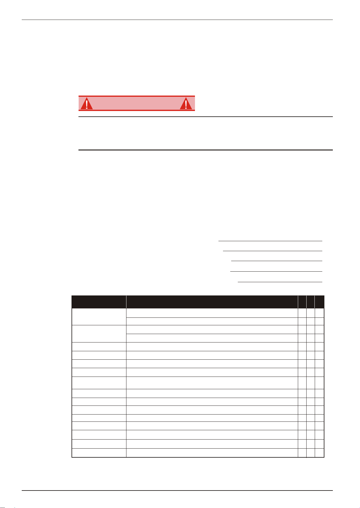
D A N G E R
FRONT TIE DOWN
AND LIFTING LUGS
REAR TIE DOWN
AND LIFTING LUGS
FORKLIFT POCKETS
(Both sides of machine)
DRIVING OR WINCHING ONTO
A TRUCK OR TRAILER
C A U T I O N
1. Fully lower the platform.
2. Turn OFF the Main Power Switch and remove the key.
3. Turn the battery switch to OFF and padlock it.
1. Secure straps to chassis tie down/lifting lugs only.
2. Place the platform onto the transport vehicle in the transport position.
3. Chock the wheels.
4. Secure the work platform to the transport vehicle with chains or straps of adequate load
capacity attached to the chassis tie down/lifting lugs.
Forklifting is for trans port only.
See spec i fi ca tions for weight of work plat form and be cer tain that the fork lift is of ad e quate ca pac ity to lift the work plat form.
Fork lift from the side us ing the 'built in' fork lift pock ets.
Figure 6: Transporting
NOTE: Do not winch faster than 0.9 m/s (3 ft/s).
1. Move the machine onto the trailer.
A.
To Drive the machine onto the transport
vehicle:
i. Move the work platform up the ramp and into
the transport position.
ii. Set the wheels straight and turn off the
machine.
iii. Chock the wheels
B.
To Winch the machine onto the transport
vehicle.
i. Move the platform up to the ramp.
ii. Attach the winch cable to the tie down/lifting
lugs.
iii. Release the parking brakes (refer to "Towing or
Winching" on page 12).
iv. Winch the platform into transport position.
v. Chock the wheels.
vi. Reset the parking brakes.
2. Secure the work platform to the transport vehicle with chains or straps of adequate load
capacity attached to the chassis tie down/lifting lugs.
Overtightening of the chains or straps at tached to the Tie Down/Lift ing Lugs may re sult in dam age to the work plat form.
Operation Manual Page 13
Maintenance
MAINTENANCE
W A R N I N G
BLOCKING THE
ELEVATING ASSEMBLY
INSTALLATION
REMOVAL
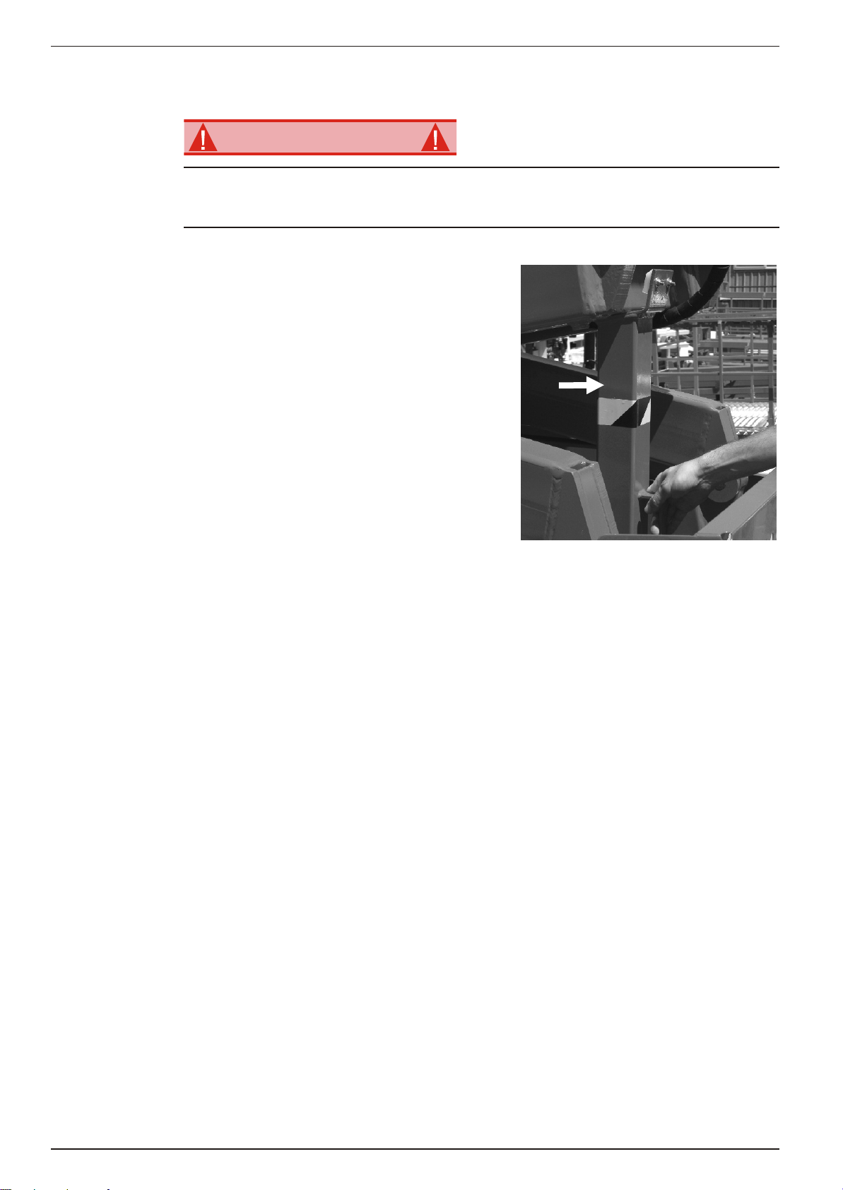
Never per form ser vice while the plat form is el e vated with out first block ing the el e vat ing as sem bly.
DO NOT stand in the el e vat ing as sem bly area while de ploy ing or stor ing the brace.
Figure 7: Scissor Brace
1. Park the work platform on firm level ground and
leave the engine running.
2. Ensure the Ground Emergency Stop Button is
pulled to the ON position.
3. Using the Ground Controls raise the scissor arm
assembly sufficiently to raise the Scissor Prop to
a vertical position.
4. Using the Ground Controls lower the scissor
arm assembly until it is firmly resting on the
prop.
1. Using the Ground Controls raise the scissor arm assembly until the safety prop can be
removed.
2. Place the scissor arm prop back into it's cradle.
3. Lower the scissor arm assembly until it reaches its stowed position.
Page 14 Operation Manual

Maintenance
BATTERY MAINTENANCE
W A R N I N G
BATTERY CHARGING
Haz ard of ex plo sive gas mix ture. Keep sparks, flame, and smok ing ma te rial away from bat tery.
Al ways wear safety glasses when work ing near bat ter ies.
bat tery fluid is highly cor ro sive. thor oughly rinse away any spilled fluid with clean wa ter.
Al ways re place bat ter ies with othe cor rect type or man u fac turer ap proved re place ments.
●
Check the battery fluid level daily, especially if the work platform is being used in a
warm dry climate.
●
If electrolyte level is lower than 10mm (3/8") above the plates add distilled water only.
DO NOT use tap water with high mineral content, as this will shorten battery life.
●
Keep the terminals and tops of the battery clean.
●
refer to the Service manual to extend battery life and for complete service instructions.
The bat tery is charged while the en gine is run ning.
Operation Manual Page 15
Inspection and Maintenance Schedule
DAILY PREVENTATIVE MAINTENANCE CHECKLIST
W A R N I N G
INSPECTION AND MAINTENANCE SCHEDULE
MAINTENANCE TABLE KEY
Y = Yes/Acceptable
PREVENTATIVE MAINTENANCE REPORT
N = No/Not Acceptable
R = Repaired/Acceptable
Date:
Owner:
Model No:
Serial No:
Serviced By:
INSPECTION OR SERVICES
RNY
COMPONENT
Battery
Check electrolyte level
Check battery condition
Chassis
Check hoses for pinch or rubbing points
Check welds for cracks
Check the exterior of the cable for pinching, binding or wear
Control Cable
Controls
Check switch operation
Drive Motors
Check for operation and leaks
Elevating Assembly
Inspect for structural cracks
Emergency Lowering
Assembly
Operate the emergency lowering mechanism and check for serviceability
Entire Machine
Check for and repair collision damage
Hydraulic Fluid
Check fluid level
Hydraulic Pump
Check for hose fitting leaks
Hydraulic System
Check for leaks
Labels
Check for peeling, missing, or unreadable labels and replace
Platform Deck & Rails
Check welds for cracks
Tires and Wheels
Check for damage
Platform Deck & Rails
Check condition of deck
The Com plete In spec tion con sists of pe ri odic vi sual and op er a tional checks, along with
pe ri odic mi nor ad just ments that as sure proper per for mance. daily in spec tion will pre vent
ab nor mal wear and pro long the life of all sys tems. The in spec tion and main te nance
sched ule should be per formed at the spec i fied in ter vals. in spec tion and main te nance
shall be per formed by per son nel who are trained and fa mil iar with me chan i cal and elec tri cal pro ce dures.
Be fore per form ing pre ven ta tive main te nance, fa mil iar ize your self with the op er a tion of the ma chine.
Al ways block the el e vat ing as sem bly when ever it is nec es sary to per form main te nance while
the plat form is el e vated.
The daily pre ven ta tive main te nance check list has been de signed for ser vice and main te nance.
Please pho to copy this page and use the check list when in spect ing the ma chine.
Page 16 Operation Manual

Daily Preventative Maintenance Checklist
NOTES:
Operation Manual Page 17
Labels
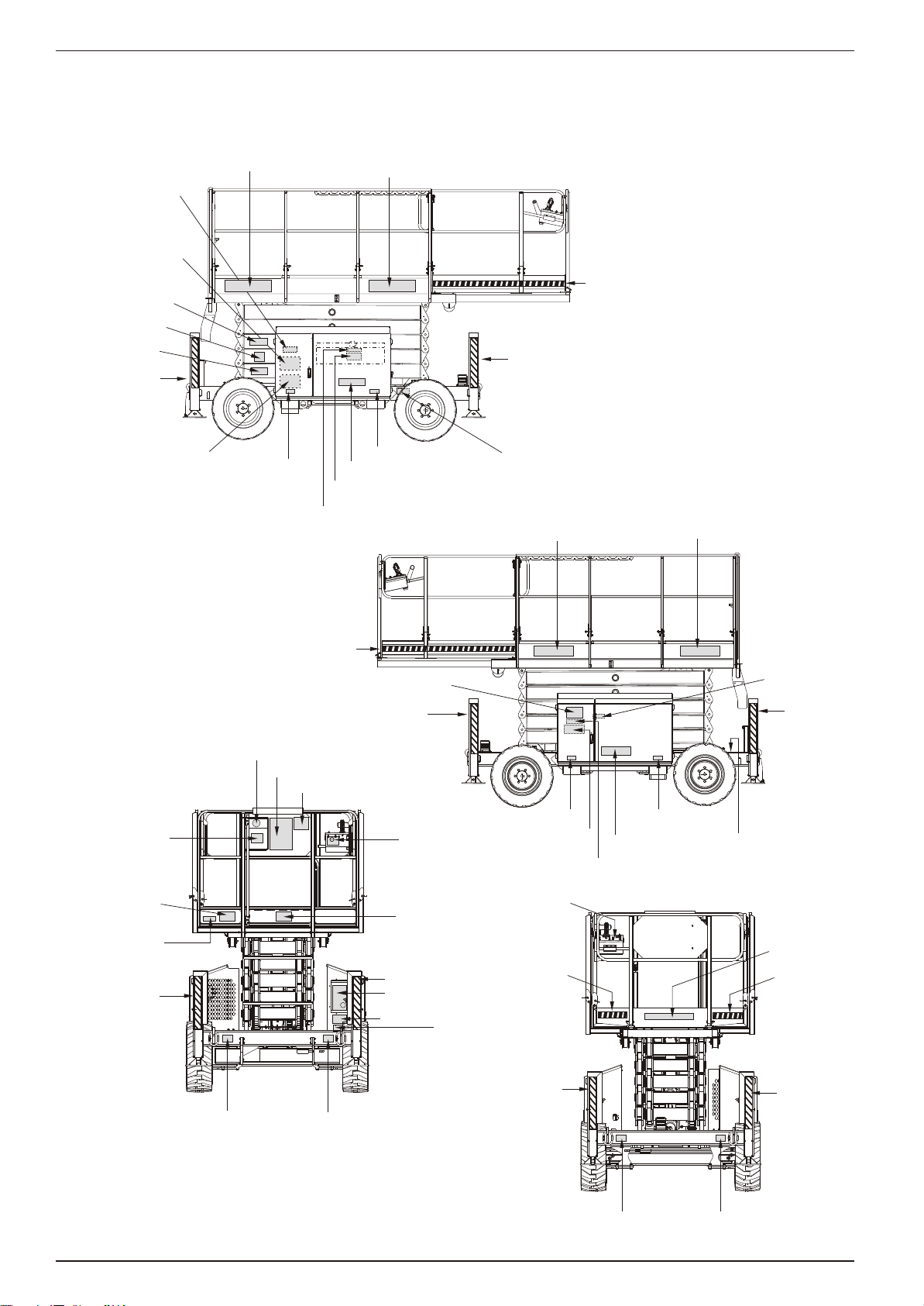
LABELS
12671
569295
300700
12816
12815-2
Inside Cabinet
Inside Cabinet
0323897
58365-6
9223-3
569295
12814
451986
96924-9
96924-9
476706
9223-3
560272
12689
96924-9
569295
12699
9223-3
605726
476706
9208
621486
12753
569295
12671
569295
621486
621486
9223-3
12815-4
Inside Cabinet
Inside Cabinet
Inside Cabinet
Inside Cabinet
Inside Cabinet
621486
9751
12574
1843
562246
451986
9223-3
0083427
0083427
0083427
0083427
9223-3
9223-3
9223-3
560240
300699
0070901E
0073298
96924-9
These la bels shall be pres ent and in good con di tion be fore op er at ing the work plat form. Be sure to
read, un der stand and fol low these la bels when op er at ing the work plat form.
Page 18 Operation Manual

Specifications
SPECIFICATIONS
X 27-RT
Nominal working height
Roll out deck size
Drive speed (below 2.4m)
Drive speed (above 2.4m)
Safe working load - Main deck
(Roll out deck not extended)
Safe working load - Main deck
Roll out deck extended - Roll out deck
Platform size
Stowed height
Stowed height (hand rails folded down)
Overall length
Overall width
Gradeability
Lift time
Turning radius (inner)
Turning radius (outer)
Maximum wind speed (12.5m/s)
Insulation rating
Tyres - Poly filled loader lug
Overall weight
Ground clearance
Maximum sound level at platform
10.28m 33' 9”
1200mm 48”
0 to 4.5kph 0 to 2.8mph
0 to 0.9kph 0 to 0.6mph
580kg 1280lbs
460kg
120kg
2.73 x 1.65m 8’ 11” x 5’ 5”
2.5m 8' 2"
1.7m 5' 8"
3.36m 11’ 0”
1.7m 5' 8"
35%
26 seconds
2.83m 9’ 3”
4.6m 15’ 1”
45km/h 28mph
Nil
27" x 10.5" x 15"
2800kg 6272lbs
350mm 13.8”
86db
1015lbs
265lbs
X-33-RT
Nominal working height
Roll out deck size
Drive speed (below 2.4m)
Drive speed (above 2.4m)
Safe working load - Main deck
(Roll out deck not extended)
Safe working load - Main deck
Roll out deck extended - Roll out deck
Platform size
Stowed height
Stowed height (hand rails folded down)
Overall length
Overall width
Gradeability
Lift time
Turning radius (inner)
Turning radius (outer)
Maximum wind speed (12.5m/s)
Insulation rating
Tyres - Poly filled loader lug
Overall weight
Ground clearance
Maximum sound level at platform
12.12m 39' 2”
1200mm 48”
0 to 4.5kph 0 to 2.8mph
0 to 0.35kph 0 to 0.22mph
450kg 990lbs
330kg
120kg
2.73 x 1.65m 8’ 11” x 5’ 5”
2.7m 8' 10"
2.0m 6' 6"
3.36m 11’ 0”
1.77m 5' 9"
35%
50 seconds
2.38m 7’ 8”
4.75m 15’ 6”
45km/h 28mph
Nil
27" x 10.5" x 15"
3620kg 7964lbs
350mm 13.8”
86db
726lbs
264lbs
Spec i fi ca tions are sub ject to change with out no tice. Hot weather or heavy use may af fect per for mance. Re fer to the Ser vice Man ual for com plete
parts and ser vice in for ma tion. This ma chine meets or ex ceeds all ap pli ca ble re quire ments of OSHA and ANSI A92.6
Operation Manual Page 19


X-27-33-RT
Seriennummern NZ 70810 - aktuelles Modell
DEUTSCH
Stellen Sie sicher, dass Sie die MODELL- und SERIENNUMMERN auf dem Gerätetypenschild angeben,
wenn Sie sich mit Upright bezüglich Wartungs- oder Ersatzteilinformationen in Verbindung setzen.
UpRight Powered Access HQ
POWERED ACCESS
www.upright.com
Vigo Centre
Birtley Road
Washington
Tyne & Wear
NE38 9DA
Tel: +44 (0) 845 1550 057
Fax: +44 (0) 845 1557 756

BETRIEBSANLEITUNG
WARNUNG
Alle Bediener müssen die Sicherheitsregeln und Betriebsanleitungen gründlich durchlesen, verstehen und
befolgen, bevor sie an irgendeiner Upright-Hocharbeitsbühne Wartungsarbeiten ausführen oder die
Arbeitsbühne in Betrieb nehmen.
Sicherheitsrichtlinien
Lebensgefahr durch
Stromschlag
Diese Maschine ist nicht
isoliert!
Kippgefahr Kollisionsgefahr
NIEMALS die Plattform ausfahren oder die
Maschine mit ausgefahrener Plattform
fortbewegen, wenn sich die Maschine nicht auf
einer festen, ebenen Fläche befindet.
Plattform NIEMALS in Position bringen,
ohne vorher sicherzustellen, dass der
Bereich über der Plattform frei von
Hindernissen und anderen Gefahren ist.
Gefahr des
Herunterfallens
NIEMALS auf das obere oder mittlere
Gestänge des Plattformgeländers klettern
und auch nicht darauf stehen oder sitzen.
VERWENDUNG DER HUBARBEITSPLATTFORM: Diese Hubarbeitsplattform dient zum Anheben von Personen und deren
Werkzeug sowie von Material, das für bestimmte Arbeiten erforderlich ist. Sie wurde speziell für Reparatur- und Montagearbeiten
sowie für Einsatzbereiche konzipiert, die sich oberhalb der Mitarbeiter befinden, sodass die Mitarbeiter nach oben gerichtet
arbeiten müssen (z. B. Decken, Kräne, Dachstrukturen, Gebäude etc.). Jede andere Verwendung der Hocharbeitsbühne ist strikt
verboten!
DIESE HUBARBEITSPLATTFORM IST NICHT ISOLIERT! Aus diesem Grund müssen Sie von stromführenden Teilen
elektrischer Anlagen einen Sicherheitsabstand einhalten!
Es ist verboten, die angegebene zulässige Maximallast zu überschreiten.Siehe Abschnitt "Besondere Einschränkungen" auf
Seite 4 für weitere Einzelheiten hierzu.
Es ist streng verboten, die Hocharbeitsbühne als Hubwerkzeug oder Kran einzusetzen (d. h. um Lasten von unten nach oben
oder von oben nach unten zu befördern).
Die für diese Maschine zulässige manuelle Kraft NIEMALS überschreiten. Siehe Abschnitt "Besondere Einschränkungen" auf
Seite 4 für weitere Einzelheiten hierzu.
VERTEILEN Sie die gesamte Plattformlast gleichmäßig auf der Plattform.
Vor Inbetriebnahme der Maschine IMMER ZUERST die Aufstellfläche im Arbeitsbereich auf Gefahren wie Bodenlöcher,
ausgelaufene Flüssigkeiten, Bodenerhebungen, Kanten oder Schutt untersuchen und diese umgehen bzw. beseitigen.
BEDIENEN Sie die Maschine nur auf Flächen, die das Gewicht der Maschine tragen können.
Maschine NIEMALS in Betrieb nehmen, wenn die tatsächliche Windgeschwindigkeit höher ist als die Windgeschwindigkeit, für die
die Maschine ausgelegt ist. Siehe "Beaufort-Skala" auf Seite 4 für weitere Einzelheiten hierzu.
IM NOTFALL NOT-AUS-Schalter drücken, um alle strombetriebenen Funktionen zu deaktivieren.
WENN EIN ALARMSIGNAL ERTÖNT, während die Plattform angehoben ist, HALTEN SIE SOFORT AN, und senken Sie die
Plattform vorsichtig ab. Fahren Sie die Maschine auf einen festen, ebenen Untergrund.
Das Hochsteigen auf den Schienen der Plattform, das Stehen oder Steigen von der Plattform auf Gebäude, Stahl- oder
Betonstrukturen von Fertighäusern usw. ist verboten!
Das Schwingtor oder andere Komponenten des Schutzgeländers zu demontieren ist verboten! Vergewissern Sie sich immer,
dass das Schwingtor geschlossen und sicher verriegelt ist!
Es ist verboten, das Schwingtor geöffnet zu halten (z. B. mit Befestigungsgurten), wenn die Plattform ausgefahren wird!
Das Erweitern der Höhe oder der Reichweite durch die Verwendung von Leitern, Gerüsten oder ähnlichen Hilfsmitteln auf der
Plattform ist verboten!
Führen Sie bei angehobener Plattform NUR DANN Wartungsarbeiten an der Maschine aus, wenn Sie die Hubeinheit blockiert
haben.
UNTERSUCHEN Sie die Maschine vor Gebrauch gewissenhaft nach gerissenen Schweißnähten, losen oder fehlenden
Befestigungselementen, Hydrauliklecks, losen Drahtverbindungen und beschädigten Kabeln oder Schläuchen.
ÜBERPRÜFEN Sie vor dem Gebrauch, dass alle Etiketten richtig angebracht und lesbar sind.
Verwenden Sie
Etiketten aufweist.
Betriebsanleitung Seite 1
NIEMALS eine Maschine, die beschädigt ist, nicht ordnungsgemäß funktioniert oder beschädigte bzw. fehlende

Das Umgehen einer Sicherheitseinrichtung ist verboten und stellt eine Gefahr für die Personen auf der Hubarbeitsplattform und
innerhalb des Arbeitsbereichs dar.
Laden Sie die Batterien NIEMALS in der Nähe von offenen Flammen oder Funkenbildung auf. Beim Aufladen von Batterien wird
explosives Wasserstoffgas freigesetzt.
Modifikationen an der Hubarbeitsplattform sind verboten bzw. dürfen nur mit der Zustimmung von UpRight durchgeführt
werden.
Sichern Sie die Arbeitsplattform NACH GEBRAUCH gegen unbefugte Benutzung, indem Sie den Schlüsselschalter ausschalten
und den Schlüssel abziehen.
Seite 2 Betriebsanleitung

I NHALT
Einführung
Allgemeine Beschreibung 4
Tragfähigkeit der Plattform 5
Manuelle Kraft 5
Beaufort-Skala 5
Alarm bei Überlastung der Hubeinheit 5
Bedienelemente und Anzeigen 6
Sicherheitsprüfung vor der Inbetriebnahme 7
Überprüfung der Systemfunktionen 8
Bedienung 9
Plattformverlängerung 9
Fahren mit abgesenkter Plattform 9
Lenkung 9
Anheben der Plattform 9
Fahren mit ausgefahrener Plattform 10
Absenken der Plattform 10
Nivellieren der Plattform 10
Notabsenkung 11
Einklappen der Schutzgitter 12
Einklappen 12
Montageanleitung 12
Ziehen oder Winden 13
Lösen der Feststellbremse 13
Nach dem täglichen Gebrauch 13
Betriebsstundenzähler 13
Transport der Arbeitsbühne 14
Vorbereitung 14
Anheben mit einem Kran 14
Per Gabelstapler 14
Fahren oder Ziehen der Maschine auf einen Lastwagen 14
Wartung 15
Blockieren der Hubvorrichtung 15
Installation der Scherenklammer 15
Verstauen der Scherenklammer 15
Wartung der Batterie 16
Aufladen der Batterie 16
Inspektions- und Wartungsplan 17
Checkliste für tägliche präventive Wartungsarbeiten 17
Etiketten 19
Technische Daten 20
Betriebsanleitung Seite 3
4
Einführung
E INFÜHRUNG
Dieses Handbuch beschreibt Einsatz und Bedienung der selbstfahrenden Arbeitsbühnen für schwierige
Gelände der Serie X-27-33-RT. Das Handbuch muss immer bei der Maschine aufbewahrt werden.
A LLGEMEINE B ESCHREIBUNG
1. Plattform
WARNUNG
Hocharbeitsbühne NICHT ohne korrekt
montiertes und angebrachtes Schutzgeländer verwenden.
2. Hubvorrichtung
Abbildung 1
3. Fahrwerk
4. Motor
5. Plattform-Bedienelemente
6. Handbuchfach
7. Fahrwerk-Bedienelemente
8. Behälter für Hydraulikflüssigkeit
5
7
Seite 4 Betriebsanleitung
 Loading...