


Engine Powered
Gasoline, Diesel,
Battery Electric,
Bi-Energy Options
OPERATORS
MANUAL
Serial Number 000001 and after
Part Number 13225A-EN
JAN 2012 (REV D)

LIMITED WARRANTY
Snorkel warrants each new machine manufactured and sold by it to be free from defects in material and workmanship for a period of one (1) year from date of delivery to a Customer or for one year after the machine has been placed in first service in a Dealer rental fleet, whichever comes first. Any part or parts which, upon examination by the Snorkel Service Department, are found to be defective, will be replaced or repaired, at the sole discretion of Snorkel, through its local Authorized Dealer at no charge.
Snorkel further warrants the structural components; specifically, the mainframe chassis, turntable, booms and scissor arms, of each new machine manufactured by it to be free from defects in material and workmanship for an additional period of four (4) years.Any such part or parts which, upon examination by the Snorkel Service Department, are found to be defective will be replaced or repaired by Snorkel through its local Authorized Dealer at no charge; however, any labor charges incurred as a result of such replacement or repair will be the responsibility of the Customer or Dealer.
The Snorkel Service Department must be notified within forty-eight (48) hours of any possible warranty situation during the applicable warranty period. Personnel performing warranty repair or replacement must obtain specific approval by Snorkel Service Department prior to performing any warranty repair or replacement.
Customer and Dealer shall not be entitled to the benefits of this warranty and Snorkel shall have no obligations hereunder unless the “Pre-Delivery and Inspection Report” has been properly completed and returned to the Snorkel Service Department within ten (10) days after delivery of the Snorkel product to Customer or Dealer’s rental fleet. Snorkel must be notified, in writing, within ten (10) days, of any machine sold to a Customer from a Dealer’s rental fleet during the warranty period.
At the direction of the Snorkel Service Department, any component part(s) of Snorkel products to be replaced or repaired under this warranty program must be returned freight prepaid to the Snorkel Service Department for inspection. All warranty replacement parts will be shipped freight prepaid (standard ground) from the Snorkel Service Department or from Snorkel’s Vendor to Dealer or Customer.
REPLACEMENT PARTS WARRANTY
Any replacement or service part made or sold by Snorkel is not subject to the preceding Limited Warranty beyond the normal warranty period of the machine upon which the part was installed.
THIS WARRANTY EXCLUDES AND SNORKEL DOES NOT WARRANT:
1.Engines,motors,tiresandbatterieswhicharemanufacturedbysupplierstoSnorkel,whofurnishtheirownwarranty. Snorkel will, however, to the extent permitted, pass through any such warranty protection to the Customer or Dealer.
2.AnySnorkelproductwhichhasbeenmodifiedoralteredoutsideSnorkel’sfactorywithoutSnorkel’swrittenapproval, if such modification or alteration, in the sole judgment of Snorkel’s Engineering and/or Service Departments, adversely affects the stability, reliability or service life of the Snorkel product or any component thereof.
3.Any Snorkel product which has been subject to misuse, improper maintenance or accident. “Misuse” includes but is not limited to operation beyond the factory-rated load capacity and speeds. “Improper maintenance” includes but is not limited to failure to follow the recommendations contained in the Snorkel Operation, Maintenance, Repair Parts Manuals. Snorkel is not responsible for normal maintenance, service adjustments and replacements, including but not limited to hydraulic fluid, filters and lubrication.
4.Normal wear of any Snorkel component part(s). Normal wear of component parts may vary with the type application or type of environment in which the machine may be used; such as, but not limited to sandblasting applications.
5.Any Snorkel product that has come in direct contact with any chemical or abrasive material.
6.Incidental or consequential expenses, losses, or damages related to any part or equipment failure, including but not limited to freight cost to transport the machine to a repair facility, downtime of the machine, lost time for workers, lost orders, lost rental revenue, lost profits or increased cost.
This warranty is expressly in lieu of all other warranties, representations or liabilities of Snorkel, either expressed or implied, unless otherwise amended in writing by Snorkel’s President, Vice President-Engineering, Vice PresidentSales or Vice President-Marketing.
SNORKEL MAKES NO WARRANTIES WHICH EXTEND BEYOND THE DESCRIPTION OF THIS LIMITED WARRANTY. SNORKEL MAKES NO IMPLIED WARRANTY OF MERCHANTABILITY OR FITNESS FOR A PARTICULAR PURPOSE AND DISCLAIMS ALL LIABILITY FOR INCIDENTAL OR CONSEQUENTIAL DAMAGES, INCLUDING BUT NOT LIMITED TO INJURY TO PERSONS OR PROPERTY.
The Customer shall make all warranty claims through its local Authorized Dealer and should contact the Dealer from whom the Snorkel product was purchased for warranty service. Or, if unable to contact the Dealer, contact the Snorkel Service Department for further assistance.
Effective July 1995

Electrical Hazard
■■Electrical Hazard Warning
DANGER
THE TL39T AERIAL WORK PLATFORM, IN STANDARD CONFIGURATION, IS
NOT ELECTRICALLY INSULATED.
If the plat form, booms, or any other conductive part of a TL39T contacts a high-voltage electrical conductor, the result can be SERIOUS INJURY or DEATH for persons on or near the machine.
GO NO CLOSER THAN THE MINIMUM SAFE APPROACH DISTANCES (M.S.A.D) - AS OUTLINED IN TABLE 1. AND FIGURE 3., ON THE NEXT PAGE.
Be sure to allow for sag and sway in the wires and the work platform.
If a TL39T comes in contact with a live electrical conductor, the entire machine can be charged.
If that happens, you should re main on the machine and not contact any other structure or object within reach. That includes the ground, adjacent buildings, poles, and any object not a part of the TL39T.
Such contact could make your body a conductor to the other object creating an electrical shock hazard resulting in SERIOUS INJURY or DEATH.
DO NOT attempt to enter or leave the TL39T until you are sure the electricity has been turned off.
If a TL39T is in contact with a live conductor, the platform operator MUST warn others on the ground in the vicinity of the TL39T to STAY AWAY from the machine, since their bodies can also form a path for electricity to ground thus creating an electrical shock hazard with possible ELECTROCUTION and
DEATH.
DO NOT attempt to operate the TL39T ground controls when the platform, booms, or any other conducting part of a TL39T is in contact with electrical wires or if there is an immediate danger of such contact.
Regard all conductors as energized.
Personnel working on or near a TL39T must be continuously aware of electrical hazards, recognizing that SERIOUS INJURY or DEATH can result if contact with an electrical wire does occur.
Rev C |
page - i |

Electrical Hazard
■■Minimum Safe Approach Distance
The TL39T is an all metal boom, NOT ELECTRICALLY INSULATED, aerial work platform. DO NOT operate it near ELECTRICAL conductors. Regard all conductors as being energized. Use the table and illustration below to determine safe clearance from electrical conductors. (Table 1 and Figure 3, below, are from ANSI/SIAA92.5–1992 Standard, reprinted with permission of Scaffold Industry Association.)
□□Table 1 - (M.S.A.D.)
Minimum Safe Approach Distance to energized (exposed or insulated power lines)
|
|
Voltage range |
Minimum safe approach distance |
|
||||||||
|
|
|
|
|
|
|
|
|
|
|
|
|
|
(phase to phase) |
|
|
(Feet) |
|
(Meters) |
|
|||||
|
|
|
|
|
|
|
|
|
|
|
|
|
|
0 to 300V |
|
|
|
|
|
|
Avoid contact |
|
|||
|
|
|
|
|
|
|
|
|
|
|
|
|
|
over 300v to 50kv |
10 |
|
|
3.05 |
|
||||||
|
|
|
|
|
|
|
|
|
|
|
|
|
|
over 50kv to 200kv |
15 |
|
|
4.60 |
|
||||||
|
|
|
|
|
|
|
|
|
|
|
|
|
|
over 200kv to 350kv |
20 |
|
|
6.10 |
|
||||||
|
|
|
|
|
|
|
|
|
|
|
|
|
|
over 350kv to 500kv |
25 |
|
|
7.62 |
|
||||||
|
|
|
|
|
|
|
|
|
|
|
|
|
|
over 500kv to 750kv |
35 |
|
|
10.67 |
|
||||||
|
|
|
|
|
|
|
|
|
|
|
|
|
|
over 750kv to 1000kv |
45 |
|
|
13.72 |
|
||||||
|
|
|
|
|
|
|
|
|
|
|
|
|
|
|
|
|
|
|
|
|
|
|
|
|
|
|
|
|
|
|
|
|
|
|
|
|
|
|
|
|
|
|
|
|
|
|
|
|
|
|
|
|
|
|
|
|
|
|
|
|
|
|
|
|
|
|
|
|
|
|
|
|
|
|
|
|
|
|
|
|
|
|
|
|
|
|
|
|
|
|
|
|
|
|
|
|
|
|
|
|
|
|
|
|
|
|
|
|
|
|
|
|
|
|
|
|
|
|
|
|
|
|
|
|
|
|
|
|
|
Denotes prohibited zone
Danger: - Do not allow machine personnel or conductive materials inside prohibited zone.
-Maintain M.S.A.D. From all energised lines and parts as well as those shown.
-Assume all electrical parts and wires are energised unless known otherwise.
Caution - Diagrams shown are only for purposes of illustrating
M.S.A.D. Work positions, not all work positions.
page - ii |
Rev C |

The most important chapter in this manual is the safety chapter - Chapter 1. Take time, now, to study it closely.
The information in Chapter 1, might save your life, prevent serious in jury, or damage to property or the TL39T.
This introduction also contains important information concerning the responsibilities of the owner of this machine.
■■Standard TL39T
The standard TL39T in cludes the following features:
●●Independently operated heavy duty hydraulic stabilizers
●●Manual stabilisers
●●540° slew
●●Heavy duty tow coupling ●●Heavy duty jockey wheel
●●Hour meter
●●Hydraulic disc brakes
●●Steel platform - 2 person capacity
●●High strength steel boom and base construction
●●Beam axle with 15” rims ●●Honda petrol engine
●●600V AC rated wire to platform ●●Stabiliser/boom interlocks
●●Stabiliser lift points
●●Gravity gate
●●Manual basket rotator ●●LED taillights
●●Height restrictor in upper cylinder to keep platform at 10.9m maximum height (TL39T only)
●●235 R15 x 75 tyres
■■Options
The following options are available for the TL39T:
●●Automatic stabilisers
●●Custom colours
●●Platform work lights ●●Air line to platform ●●Flashing light
●●Spare wheel
●●10.9m height lockout kit ●●240V110V outlet in platform
●●Battery isolate switch
●●Platform foot switch
Introduction
●●Alternative power optionsDiesel engined
24VDC power240V power110V power
●●Bi-Energy optionsPetrol / 24VPetrol / 240VDiesel / 24VDiesel / 240V24V / 240V
●●Platform overload protection
■■Operation Manual
This manual provides information for safe and proper operation of the aerial platform.
Read and understand the information in this Operator’s manual before operating this machine on a job site.
Additional copies of this manual may be ordered from Snorkel. Supply the model and manual part number from the front cover to assure that the correct manual will be supplied.
All information in this manual is based on the latest product information at the time of publication. Snorkel reserves the right to make product changes at any time without obligation.
■■Photographs
Photographs are taken to represent the machine and its component parts as clearly as possible. How ever, there may be minor differences between the photographs and your machine. This represents individual customer preferences and Snorkel’s on going commitment to product development.
■■Safety Alerts
A safety alert symbol is used through out this manual to indicate danger, warning, caution, and important instructions. Follow these instructions to reduce the like li hood of personal injury, property damage, or damage to the machine.
The terms danger, warning, and caution indicate varying degrees of personal injury or property damage that can result if the instruction is not followed.
! DANGER
Denotes an imminently hazardous situation which, if not avoided, will result in death or serious injury.
Rev C |
page - iii |

Introduction
|
! WARNING |
|
Read and understand the information in this |
||||
Denotes a potentially hazardous situation |
manual and on the placards and decals on the |
||||||
machine before operating the MHP on the job. |
|||||||
which, if not avoided, could result in death or |
■■Maintenance |
|
|||||
serious injury. |
|
|
|
|
|||
|
! CAUTION |
|
Every person |
who maintains, |
inspects, tests, |
||
|
|
or repairs these machines, and every person |
|||||
Denotes a potentially hazardous situation |
supervising any of these functions, must be properly |
||||||
which, if not avoided, may result in minor or |
trained and qualified to do so. |
|
|||||
moderate injury. |
|
|
|
This Operators Manual provides a Pre-operational |
|||
It may also be used to alert against unsafe |
Inspection procedure that will help you keep your |
||||||
practices or action which may result in |
MHP in good operating condition. |
|
|||||
damage to the MHP. |
|
|
Do not perform other maintenance unless you are |
||||
|
! IMPORTANT |
|
a trained mechanic, qualified to work on the MHP. |
||||
|
|
Call qualified maintenance personnel if you find |
|||||
Denotes |
important |
information |
pertaining |
problems or malfunctions. |
|
||
|
|
|
|||||
to settings, capacities, or conditions, which |
Do not modify this machine without written approval |
||||||
could, if ignored, lead to machine damage or |
from the Engineering Department of Snorkel New |
||||||
future hazardous situations. |
|
Zealand. Modification may void the warranty, |
|||||
It is also |
used |
to |
alert the reader to pay |
adversely affect |
stability, or affect |
the operational |
|
characteristics of the MHP. |
|
||||||
careful attention |
to |
a particular |
passage of |
|
|||
|
|
|
|||||
text in the manual. |
■■Responsibilities of Parties |
|
Notes
Notes are used to provide special information or helpful hints to assist in aerial platform operation, but do not indicate a hazardous situation.
■■Operation
The MHP ae rial platform has built-in safety features and has been factory tested for compliance with
Snorkel specifications and industry standards. How ever, any personnel lifting device can be potentially dangerous in the hands of untrained or careless operators.
Training is vitally important and must be performed under the direction of a QUALIFIED person. You must display proficiency in knowledge and actual operation of the MHP before using it on a job site.
Before operation of the MHP you must read and understand the operatingin structions in this manual as well as the decals, warnings, and in structions on the machine itself.
Before operating the MHP you must be AUTHORIZED by the person in charge to do so and the operation of the MHP must be within the scope of the machine specifications.
! IMPORTANT
It is imperative that all owners and users of the MHP read, understand, and conform to all applicable regulations.
Ultimate compliance to OSHA regulations is the responsibility of the user and their employer.
! IMPORTANT
ANSI Standard A92.6 clearly identifies requirements of all parties who might be involved with Self-Propelled Elevating Work Platforms.
AUSTRALIAN / NZ STANDARD 2550-10 Also identifies the requirements of all parties who might be involved with Boom-Supported Elevating Work Platforms.
NOTE - Standards
It is the responsibility of the owner to ensure that the person operating the TL39T is provided with all the relevant information relating to standards and codes of practice applicable in their region.
! WARNING
The potential for an accident increases when the aerial platform is operated by personnel who are not trained and authorised. death or serious injury can result from such accidents.
page - iv |
Rev C |

Introduction
In summary
●●Only trained and authorised operators should be permitted to operate the equipment.
●●All manufacturers operating instructions, and all safety rules, and all employers safety rules, and all OSHA and other government or local authority safety rules should be strictly adhered to.
●●Repairs and adjustments should be made only by qualified and trained maintenance personnel.
●●No modification should be made to the equipment without prior written consent of the Engineering Department, Snorkel New Zealand.
●●Make a pre-start inspection of the MHP at the beginning of each shift. A malfunctioning machine must not be used.
●●Make an inspection of the work place to locate possible hazards before operating the MHP.
■■Additional Information
For additional information, contact your local dealer or Snorkel at:
Snorkel New Zealand, PO Box 1041
Levin 5540
New Zealand
Rev C |
page - v |
Electrical Hazard
Electrical Hazard Warning ....................................... |
i |
Minimum Safe Approach Distance ......................... |
ii |
Table 1 - (M.S.A.D.) .............................................. |
ii |
Introduction |
|
Standard TL39T .................................................... |
iii |
Options .................................................................. |
iii |
Operation Manual .................................................. |
iii |
Photographs .......................................................... |
iii |
Safety Alerts .......................................................... |
iii |
Operation .............................................................. |
iv |
Maintenance .......................................................... |
iv |
Responsibilities of Parties ..................................... |
iv |
In summary ........................................................... |
v |
Additional Information ............................................ |
v |
1. Safety |
|
Safe Operation ................................................... |
1-1 |
Electrocution Hazards ........................................ |
1-1 |
Minimum safe approach distance .................... |
1-1 |
Pre-start Inspection ............................................ |
1-2 |
Work Place Inspection and Practices ................. |
1-2 |
Operation ........................................................... |
1-3 |
Tipover and Falling Hazards .............................. |
1-3 |
General Safety Precautions ............................... |
1-4 |
Hydraulic System Precautions ........................... |
1-4 |
Fire Prevention ................................................... |
1-4 |
Engine and Fuel Handling Precautions .............. |
1-4 |
Batteries ............................................................. |
1-4 |
Height Restriction ............................................... |
1-5 |
Height Restriction on TL39T .............................. |
1-5 |
10.9 Metre Restriction Kit ................................... |
1-5 |
Safety Decals and Placards ............................... |
1-5 |
2. Safety Devices |
|
Safety Device Information ................................... |
2-1 |
Emergency Stop Switches .................................. |
2-1 |
At ground control box ........................................ |
2-1 |
At platform control box ...................................... |
2-1 |
Other Safety Devices .......................................... |
2-1 |
Lanyard anchor points ....................................... |
2-1 |
Gravity gate ....................................................... |
2-2 |
Guardrails .......................................................... |
2-2 |
Height restriction on TL39T ............................... |
2-2 |
10.9m height restriction kit (Option) ................. |
2-2 |
Enable switch ................................................... |
2-2 |
Enable switch (foot) – Optional ........................ |
2-3 |
Bubble level ...................................................... |
2-3 |
RCD/ELCB AC outlet (Option) ......................... |
2-3 |
Flashing light (Option) ....................................... |
2-3 |
3. Specifications
Table of Contents
General Specifications ........................................ |
3-1 |
Specifications MHP14AT ..................................... |
3-1 |
Specifications TL39T ........................................... |
3-2 |
Engine Data ........................................................ |
3-3 |
Working Envelope - TL39T .................................. |
3-4 |
Nomenclature ...................................................... |
3-5 |
4. Gauges |
|
Hourmeter ........................................................... |
4-1 |
Level Bubble ....................................................... |
4-1 |
Hydraulic Oil Level .............................................. |
4-1 |
5. Shut-offs and Circuit Breakers |
|
RCD/ELCB Outlet (option) .................................. |
5-1 |
Main Circuit Breaker ............................................ |
5-1 |
Stabilisers ............................................................ |
5-1 |
6. Controls |
|
Controls Description ............................................ |
6-1 |
Controls and Control Decal Locations ............... |
6-1 |
Ground Control Box ............................................ |
6-2 |
Lower controls / indicators ................................ |
6-2 |
Platform Control Box ........................................... |
6-3 |
Upper controls / indicators ................................ |
6-3 |
Stabiliser Controls (Manual) ................................ |
6-5 |
Self Levelling Stabilisers (Option) ....................... |
6-6 |
7. Pre-operational Inspection |
|
Pre-operational Inspection Table ......................... |
7-1 |
Engine Fuel Level ............................................... |
7-2 |
Fuel Tank Cap ..................................................... |
7-2 |
Fuel Leaks ........................................................... |
7-2 |
Engine Oil Level .................................................. |
7-2 |
Operator’s Manual .............................................. |
7-2 |
Wiring Harnesses ................................................ |
7-2 |
Battery Terminals ................................................ |
7-3 |
Battery Fluid Level .............................................. |
7-3 |
Hydraulic Oil Level .............................................. |
7-3 |
Hydraulic Oil Leaks ............................................. |
7-3 |
Bolts and Fasteners ............................................ |
7-4 |
Wheels and Tyres ............................................... |
7-4 |
Tyre Pressure .................................................... |
7-4 |
Structural Damage and Welds ............................ |
7-5 |
Lanyard Anchor Points ........................................ |
7-5 |
Platform Gravity Gate .......................................... |
7-5 |
Platform Guardrails ............................................. |
7-5 |
Platform Access Ladder ...................................... |
7-5 |
Flashing Light (option) ......................................... |
7-6 |
Ground Control Switches .................................... |
7-6 |
Emergency Lower ............................................... |
7-6 |
Ground Station .................................................... |
7-6 |
Upper control box .............................................. |
7-6 |
Platform Control Switches ................................... |
7-7 |
Rev C |
page - vii |

Table of Contents
AC Outlet RCD/ELCB (option) ............................ |
7-7 |
Placards and Decals ........................................... |
7-7 |
Placards and Decals ........................................... |
7-7 |
Standard placards and decals ........................... |
7-7 |
Decal list ............................................................ |
7-8 |
Decal inspection drawing .................................. |
7-9 |
8. Operation |
|
Operating Procedures ......................................... |
8-1 |
Control Stations ................................................... |
8-1 |
Emergency Stopping ........................................... |
8-1 |
Emergency Stopping ........................................... |
8-1 |
Operation Considerations ................................... |
8-1 |
Stabiliser Operation ............................................. |
8-1 |
Using the manual stabiliser valves .................... |
8-2 |
Raising the manually operated stabilizers ......... |
8-2 |
Self levelling stabilisers (Optional) ...................... |
8-3 |
Setting the stabilisers manually ......................... |
8-3 |
Unlocking the boom ............................................ |
8-3 |
Starting From Ground Control Box ...................... |
8-3 |
Starting From Platform Control Box .................... |
8-4 |
Moving The Platform ........................................... |
8-5 |
From ground control box ................................... |
8-5 |
From platform control box ................................. |
8-5 |
Rotating the platform ......................................... |
8-6 |
Securing for Day ............................................... |
8-6 |
9. Emergency Operation |
|
Emergency Operation Procedures ...................... |
9-1 |
Emergency Operation Procedures ...................... |
9-1 |
Operation from platform control box .................... |
9-1 |
Operation from ground control position ............... |
9-2 |
10. Stowing and Transporting |
|
Stowing ............................................................. |
10-1 |
The correct stowed position is shown here ..... |
10-1 |
Transporting ...................................................... |
10-1 |
Trailering ......................................................... |
10-1 |
Securing to a Transport Vehicle ...................... |
10-1 |
Towing ............................................................... |
10-2 |
11. Options |
|
Bi-Energy, Petrol/Diesel / 24V DC ..................... |
11-1 |
DC motor ......................................................... |
11-1 |
DC motor operation ......................................... |
11-1 |
DC motor battery switch .................................. |
11-1 |
Setting the manual stabilizers ......................... |
11-1 |
Setting the automatic stabilizers ..................... |
11-1 |
Operation ........................................................ |
11-2 |
Batteries .......................................................... |
11-2 |
Battery charger ................................................ |
11-2 |
Batteries - general maintenance ..................... |
11-3 |
Batteries – charging ........................................ |
11-3 |
Bi-Energy, Petrol/Diesel / 240V AC ................... |
11-3 |
AC motor ......................................................... |
11-3 |
AC motor operation ......................................... |
11-3 |
AC power connection ...................................... |
11-4 |
Operation ........................................................ |
11-4 |
Bi-Energy, Hydraulic Oil Tank .......................... |
11-4 |
Other Options .................................................... |
11-4 |
Air Line To Platform ........................................... |
11-4 |
Work Lights ....................................................... |
11-4 |
Flashing Light .................................................... |
11-4 |
Battery Isolate Switch ........................................ |
11-4 |
Alternative Power Options ................................. |
11-4 |
RCD/ELCB AC Outlet ........................................ |
11-4 |
Self Levelling Stabiliser ..................................... |
11-5 |
Spare Wheel ..................................................... |
11-5 |
Platform Foot Switch ......................................... |
11-5 |
10.9 Metre Height Restriction Kit ...................... |
11-5 |
Platform Overload Protection ............................ |
11-6 |
12. Fire Fighting and Chemical Control |
|
Hazardous Components ................................... |
12-1 |
Battery, Lead/Acid (UN 2794) .......................... |
12-1 |
Gasoline (UN 1203) ........................................ |
12-2 |
Hydraulic Oil (UN 1270) .................................. |
12-3 |
Motor Oil (UN 1270) ........................................ |
12-3 |
13. Operator’s Troubleshooting |
|
Troubleshooting ................................................ |
13-1 |
Operator Troubleshooting Chart ...................... |
13-1 |
Appendix A. Glossary
page - viii |
Rev C |
■■Safe Operation
Knowledge of the information in this manual, and proper training, provide a basis for safely operating the TL39T. Know the location of all the controls and how they operate to act quickly and responsibly in an emergency.
Safety devices reduce the likelihood of an accident. Never disable, modify, or ignore any safety device.
Safety alerts in this manual indicate situations where accidents may occur.
If any mal function, hazard or potentially unsafe condition relating to capacity, intended use, or safe operationis suspected, stop the operation of the MHP and seek assistance.
The operator bears ultimate responsibility for following all manufacturers instructions and warnings, regulations and safety rules of their employer and/or any country or regional law.
■■Electrocution Hazards
The TL39T is an all metal boom aerial work platform and is not electrically insulated.
Do not operate it near electrical conductors. Regard all conductors as being energized. Do not operate out side during a thunderstorm.
Minimum safe approach distance
Minimum safe approach distances to energised power lines and their associated parts must be observed wile operating the MHP.
Denotes prohibited zone
Caution: - Diagrams shown are only for purposes of illustrating
M.S.A.D. Work positions, not all work positions.
Figure 1 - Minimum Safe Approach Distance
ANSI A92.5
1. Safety
! DANGER
The MHP is not electrically insulated. Death or serious injury can result from contact with, or inadequate clearance from, an energised conductor.
Do not go closer than the minimum safe approach distance.
ANSI publications define minimum distances that must be observed when working near bus bars and energised power lines. Figure 1 and Table 1 are reprinted courtesy of the Scaffold industry
Association, ANSI/SIAA92.5.
Voltage Range |
Minimum Safe Approach |
||
|
Distance |
||
(Phase to Phase |
|
|
|
Feet |
|
Metres |
|
|
|
||
0 to 300V |
|
Avoid Contact |
|
Over 300V to 50kV |
10 |
|
3.05 |
Over 50kV to 200kV |
15 |
|
4.60 |
Over 200kV to 350kV |
20 |
|
6.10 |
Over 350kV to 500kV |
25 |
|
7.62 |
Over 500kV to 750kV |
35 |
|
10.7 |
|
|
|
|
Table 1 - Minimum Safe Approach Distance
ANSI 92.5
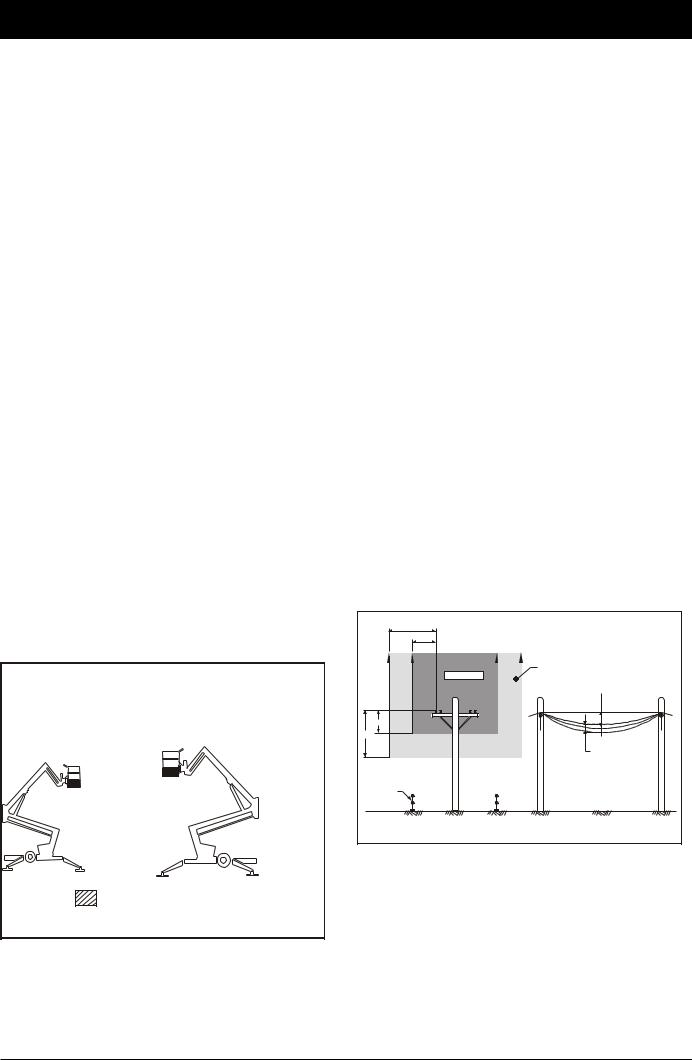
Australian Standard AS2550.10 defines minimum distances that must be observed when working near live aerial conductors up to and including 133kV (see Figure 2).
CLEARANCES FROM LIVE AERIAL CONDUCTORS |
|
6.4 |
(Dimensions are in metres) |
3 |
|
|
Spotter |
No go zone |
required |
|
zone |
3 |
Sag |
|
|
6.4 |
|
|
Variations |
|
in Sag |
Personal |
|
protection |
|
n |
|
barriers |
|
FRONT VIEW |
SIDE VIEW |
Distribution Lines Up to and Including 133kV |
|
Figure 2 - Minimum Safe Approach Distance
AS 2550.10
Rev C |
page 1-1 |

1. Safety
■■Pre-start Inspection
At the start of each work shift, the TL39T shall be given a visual inspection and function test. See the “Pre-operational Inspection and Maintenance” chapter 7, in this manual for a list of items to inspect and test.
! WARNING
DO NOT operate the TL39T unless you are trained and authorized, understand the operation characteristics of the TL39T, and have inspected and tested all functions to be sure they are in proper working order.
! DANGER
NEVER use an TL39T that has a known fault or is malfunctioning in any way until the machine has been repaired by a qualified technician.
Operating a machine in faulty condition could result in death or serious injury.
NOTE:
Whilst some of the safety rules and guidelines that follow may not apply specifically to this machine
(e.g. references to driving) they are included as part of an overall safety strategy relating to the use of elevating work platforms.
■■Work Place Inspection and Practices
Do not use the TL39T as a ground for welding. Ground to the work piece.
Be fore the TL39T is used, and during use, check the area in which the TL39T is to be used for possible hazards such as, but not limited to:
●●Drop-offs or holes. ●●Side slopes.
●●Bumps and floor obstructions. ●●Debris.
●●Overhead obstructions and electrical conductors.
●●Hazardous locations.
●●Inadequate surface and support to withstand all load forces imposed by the aerial platform in all operating configurations.
●●Wind and weather conditions.
●●Presence of unauthorized persons. ●●Other possible unsafe conditions.
Before the TL39T is used, determine the hazard classification of any particular atmosphere or
location according to ANSI/NFPA 505.
Any TL39T operated in a hazardous location must be approved and of the type required by ANSI/ NFPA 505.
While operating the MHP a recommended safety practice is to have trained and qualified personnel in the immediate work area of the TL39T to:
●●Help in case of an emergency.
●●Operate emergency controls as required.
●●Watch for loss of control by platform operator.
●●Warn the operator of any obstructions or hazards that may not be obvious to them.
●●Watch for soft terrain, sloping surfaces, dropoffs, etc., where stability could be jeopardized.
●●Watch for bystanders and never allow anyone to be under, or to reach through the booms while operating the aerial platform.
! DANGER
Pinch points may exist between moving components. Death or serious injury can result from becoming trapped between components, buildings, structures, or other obstacles. Make sure there is sufficient clearance around the machine before moving the chassis, booms, or platform. Allow sufficient room and time to stop movement to avoid contact with structures or other hazards.
Keep ground personnel from under the platform when the plat form is raised.
Secure all accessories, containers, tools, and other materials in the platform to prevent them from accidentally falling or being kicked off the platform.
Always look in the direction of travel. Drive with care and at speeds compatible with the work-place conditions. Use caution when driving over rough ground, on slopes, and when turning.
Do not engage in any form of “horseplay” or “stunt driving” while operating the TL39T.
Do not permit riders on the machine anyplace other than on the platform.
Remove all loose objects stored in or on the machine, particularly in the platform. Remove all objects which do not belong in or on the machine.
page 1-2 |
Rev C |

1. Safety
Never steady the platform by positioning it against another platform.
Do not operate an TL39T that is damaged or not functioning properly. Do not use the MHP until the machine has been repaired by a qualified maintenance person.
Do not operate a TL39T that does not have all its decals and placards attached and legible.
Watch for by stand ers and never allow anyone to be under, or to reach through, the machine and its equipment while operating.
Use the recommended transport device when loading the machine.
■■Operation
If you encounter any suspected malfunction of the aerial platform, or any hazard or potentially unsafe condition relating to capacity, intendeduse, or safe operation, cease operation immediately and seek assistance from management.
Use three points of sup port when get ting on or off the platform (two hands and one foot or a similar set of points). Keep the platform clean.
Maintain a firm footing on the platform floor. Operate the controls slowly and deliberately to avoid jerky and erratic operation. Always stop the controls in neutral before going in the opposite direction.
Do not dismount while the platform is in motion or jump off the machine.
Do not start until all personnel are clearly away from the machine.
Never cover the floor grating or otherwise obstruct your view below. Make sure the area below the platform is free of personnel before lowering.
■■Tipover and Falling Hazards
Operate the MHP only on a firm, flat, level surface capable of withstanding all load forces imposed by the TL39T in all operating conditions.
! DANGER
The MHP can tip over if it becomes unstable. Death or serious injury can result from a tip over accident. Do not drive or position the MHP platform for elevated use near any drop ff, hole, slope, soft or uneven ground, or other tip over hazard.
Do not operate the TL39T from a position on trucks, trailers, railway cars, floating vesels, scaffolds, or similar equipment unless the application is approved in writing by Snorkel.
Care shall be taken to prevent rope, electric cords, and hoses, etc., from becoming entangled in the aerial platform. If the platform or elevating assembly becomes caught, snagged, or otherwise prevented from normal motion by an adjacent structure or other obstacle such that control reversal does not free the platform, remove all personnel from the platform before attempts are made to free the platform using ground controls.
Under normal working conditions it is best not to transfer from the platform to another structure or vice versa, unless that is the safest way to do the job. Each situation must be judged separately taking the work environment into account. The following guidelines apply:
1.Where possible, place the work platform over a roof or walking structure to do the transfer.
2.Transfer your anchorage from one structure to another before you step across.
3.Remember, you might be departing the work platform to a structure where fall arrest is required.
4.Do not climb over or through the guardrails. Use the platform entrance.
All platform occupants MUST wear and use fall restraint. At tach fall restraints to the platform lanyard anchor points.
Do not exceed the unrestricted platform capacity as indicated on the capacity placard at the entrance to the platform. Do not carry loads from any point outside of the platform.
Make sure that all protective guards, cowlings, and doors are in place and secure. Be sure the guardrail system, including the gate, is in place and secure.
Do not climb on the guardrails or use ladders, planks, or other devices to extend or increase your work position from the platform.
Do not use the MHP as a crane, hoist, or jack, or for any other purpose other than to position personnel, their tools, and materials.
Do not operate the TL39T in winds, or wind gusts, of 28 mph, 45kph 12.5 m/s) or more.
! DANGER
Do not add banners, flags, screens or shelters etc., to areas of the MHP that are exposed to
Rev C |
page 1-3 |

1. Safety
wind forces as this will increase the wind load ing and effect stability
■■General Safety Precautions
Do not modify the TL39T in any way.
When parts or components are replaced, they shall be identical or equivalent to original Snorkel parts or components.
Do not override any of the safety features of the TL39T.
■■Hydraulic System Precautions
The hydraulic system contains hoses with hydraulic fluid under pressure.
! DANGER
Hydraulic fluid escaping under pressure can have enough force to inject fluid into the flesh. Serious infection or reaction can result if medical treatment is not given immediately.
In case of injury by escaping hydraulic fluid, seek medical attention at once.
DO NOT place your hand or any part of your body in front of escaping hydraulic fluid. Use a piece of cardboard or wood to search for hydraulic leaks.
Do not attempt repairs to hydraulic systems unless you are trained. Refer to experienced repair personnel for help.
■■Fire Prevention
Never operate your MHP near a flame or spark. Hydraulic oil and gasoline are flammable and can explode.
NOTE:
This machine is equipped with an internal combustion engine (in it’s standard configuration) and should not be used on or near any unimproved forest-covered, brush-covered or grass covered land unless the engine’s exhaust system is equipped with a spark arrester meeting applicable laws. If a spark arrester is used, it should be maintained in effective working order by the operator.
■■Engine and Fuel Handling Precautions
! WARNING
Engine exhaust contains carbon monoxide, a poisonous gas that is invisible and odorless. Breathing engine exhaust fumes can cause death or serious illness. Do not run the
engine in an enclosed area or indoors without adequate ventilation.
Only refuel your MHP out doors in a clear area void of gas fumes or spilled gas.
Never remove the fuel cap or refuel a gasoline engine while the engine is running or hot. ALWAYS allow the engine to cool before refueling. Never allow fuel to spill on hot machine components.
! DANGER
DO NOT smoke or permit open flames while fueling or near fueling operations.
Maintain control of the fuel filler nozzle when filling the tank.
! CAUTION
ENSURE you use an approved fuel container with appropriate fuel filler nozzle (see picture below)
Do not fill the fuel tank to capacity. Allow room for
expansion.
If gasoline is spilled, clean up spilled fuel immediately, push/tow the MHP away from the area of the spill and avoid creating any source of ignition until the spilled fuel has evaporated.
Tighten the fuel tank cap securely. If the fuel cap is lost, replace it with an approved cap from Snorkel. Use of a non-approved cap without proper venting may result in pressurization of the tank.
Never use fuel for cleaning purposes.
For diesel engines, use the correct fuel grade for the operating season.
■■Batteries
Charge batteries in a well ventilated area free of flame, sparks, or other hazards that might cause fire or explosion.
! WARNING
page 1-4 |
Rev C |

1. Safety
Batteries give off hydrogen and oxygen that can combine explosively. Death or serious injury can result from a chemical explosion.
Do not smoke or permit open flames or sparks when checking batteries.
! CAUTION
Battery acid can damage the skin and eyes. Serious infection or reaction can result if medical treatment is not given immediately. Wear face and eye protection, rubber gloves and protective clothing when working near batteries.
! CAUTION
If acid contacts your eyes, flush immediately with clear water and get medical attention. If acid contacts your skin, wash off immediately with clear water.
■■Height Restriction
! IMPORTANT
The height restrictor fitted to the standard
TL39T, is not the same device as the 10.9m restriction kit, although both of these devices achieve the same result of restricting the maximum height of the platform to 10.9m from the ground.
This is to allow the unit to be operated by unlicensed operators in accordance with Australian legislation.
! WARNING
An Australian operator MUST hold a WP
Certificate of Competency in order to operate the machine at heights in excess of 11m.
■■Height Restriction on TL39T
The TL39T (in standard mode) is fitted with a restrictor in the upper hydraulic lift cylinder to keep the platform to a maximum height of 10.9m.
■■10.9 Metre Restriction Kit
Machines that are built for the Australian market may be fitted with a 10.9m restriction kit.
This kit which can be fitted to the MHP14AT is fitted to restrict the maximum height to the platform floor at 10.9 m from the ground.
Note:
See the Options chapter page 5 for details concerning this kit.
■■Safety Decals and Placards
There are a number of safety decals and placards on the TL39T. Their locations and descriptions are shown in this section on the following pages. Take time to study them.
! CAUTION
Be sure that all the safety decals and placards on the TL39T are legible.
Clean or replace them if you cannot read the words or see the pictures. Clean with soap & water and a soft cloth. Do not use solvents.
Rev C |
page 1-5 |

1. Safety
page 1-6 |
Rev C |

1. Safety
Rev C |
page 1-7 |

1. Safety
page 1-8 |
Rev C |
■■Safety Device Information
For emergency operation controls and procedures, see the “Emergency Operation” chapter 9, in this manual.
The devices listed in this chapter are safety devices.
They are on the TL39T to increase safety in the work place for both the operator and other people near the TL39T.
! CAUTION
DO NOT bypass, disable, modify, or ignore any of these devices. Check them carefully at the start of each work shift to see that they are in working order (see “Pre-operational Inspection” chapter 7). If any is found to be defective, remove the TL39T from service immediately until a qualified service technician can make repairs.
■■Emergency Stop Switches
At ground control box
Figure 2.1 - Emergency Stop Switch at
Ground Control Box
Press the red EMERGENCY STOP button in, at any time, under any conditions, and the entire machine stops, and nothing moves. This switch must be out (on) for anything on the TL39T to work. Pull the switch and it will pop out (on).
2. Safety Devices
At platform control box
Figure 2.2 - Emergency Stop Switch at
Platform Control Box
Press the red EMERGENCY STOP button in, at any time, under any conditions, and the entire machine stops, and nothing moves. This switch must be out (on) for anything on the TL39T to work. Pull the switch and it will pop out (on).
NOTE:
The ground control box is designed to override the platform control box. If the platform control box EMERGENCY STOP switch is in (off) the ground control box can still be used to start and operate the TL39T.
■■Other Safety Devices
Lanyard anchor points
Figure 2.3 - Lanyard Anchor Points
All personnel on the platform should attach their fall restraint lanyards to one of the lanyard anchor points.
The lanyard anchors are located at the rear of the platform floor.
Rev C |
page 2-1 |

2. Safety Devices
Gravity gate
Figure 2.4 - Gravity Gate
The gravity gate is the place in the platform guardrail system where you should enter and leave the platform. Raise the gate and step under it onto the platform. Once you have entered the platform and attached your fall restraint lanyard to an anchor point, check to see that the gravity gate has fallen back into place.
Guardrails
Figure 2.5 - Guardrails
The guardrails help protect you from falling off the platform. Be sure the guardrails are properly installed and that the gravity gate or swinging gate is in place.
Height restriction on TL39T
The TL39T (in standard mode) is fitted with a restrictor in the upper hydraulic lift cylinderto keep the platform to a maximum height of 10.9m.
10.9m height restriction kit (Option)
This kit may be fitted to machines manufactured for the Australian market.
It is fitted to restrict the maximum height to the platform floor to 10.9m from the ground. This is to allow the unit to be operated by unlicensed operators in accordance with Australian legislation.
Note - Height Restriction Kit
See the Options chapter page 5 for details concerning this kit.
Enable switch
The enable switch must be operated in conjunction with the boom/platform moving function you select.
The purpose of this switch is to prevent the platform from moving if something or someone accidentally pushes one of the boom/platform moving controls.
There are enable switches fitted to both the Upper and Lower Control Boxes.
Figure 2.6 - Enable Switch, Platform Control
Box
Figure 2.7 - Enable Switch, Ground Control
Box
page 2-2 |
Rev C |
2. Safety Devices
Enable switch (foot) – Optional |
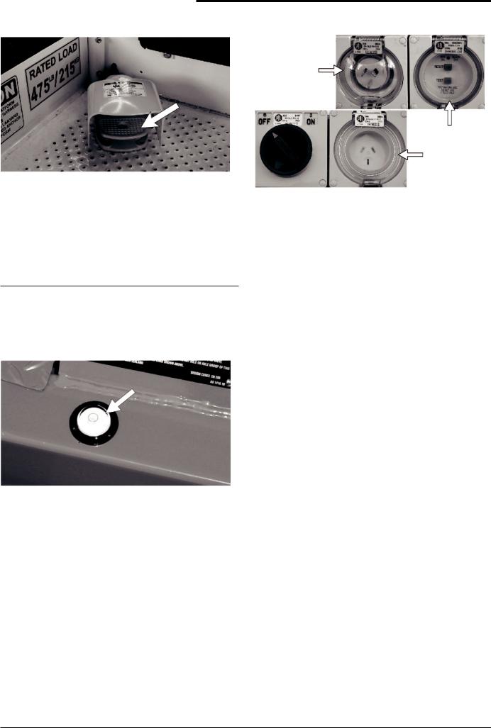
RCD/ELCB AC outlet (Option) |
Figure 2.8 - Enable Switch (Foot)
The foot switch performs the same function as the standard enable switch described above. Stepping on the foot switch is an action that must be performed, at the same time as another action, to make the booms/platform move.
Note:
If you have the optional ‘foot switch’ fitted the
Enable switches on the Upper Control Box and the Ground Control Box will still function.
Bubble level
Power Input
Connector
At Base
RCD At Base
Power Outlet
At Platform
Figure 2.10 - RCD/ELCB AC Outlet, Vertical
Mounting
The RCD (Residual Current Device) is located at the base and will protect against short circuits to earth. When there is a short circuit the RCD will shut down the 230v AC power to the platform outlet.
To reset the outlet disconnect the power tool lead from the platform box and reset the RCD at the base. If the problem persists call a trained service technician.
Flashing light (Option)
The flashing light alerts people that the booms / platform of the TL39T are moving. The light flashes at about one flash per second any time the MASTER KEY switch is on. There is no ON/OFF switch for the flashing light, it cannot be turned off while the TL39T is running.
Figure 2.9 - Bubble Level
A bubble level is located on the trailer side rail, beside the outrigger controls. Watch the bubble level while you set the stabilisers. Lower the stabilisers, one at a time, just enough to center the bubble in the circle on top of the guage. When the bubble is centered the platform is level and can be safely raised.
Rev C |
page 2-3 |

3. Specifications
The Snorkel TL39T are boom supported elevating work platforms built to conform to Australian Standard AS1418-10 Elevating Work Platforms.
NOTE:
For further details regarding lubricants, maintenance schedules and service please refer to the Maintenance and Repair Parts Manual for this machine.
■■General Specifications
■■Specifications MHP14AT
|
|
|
SPECIFICATIONS |
MHP14AT |
|
|
|
|
Nominal working height |
13.5m |
44.3’ |
|
|
|
Maximum height to basket floor |
11.5m |
37.7’ |
|
|
|
Maximum outreach |
6.4m |
21.0’ |
|
|
|
Maximum width of base |
|
|
Stabilisers retracted |
1.6m |
5.2’ |
Stabilisers extended |
3.6m |
11.8’ |
|
|
|
Safe working load (unrestricted) |
215kg |
474lbs |
|
|
|
Platform size |
1.15 x 0.70m |
3.8’ x 2.3’ |
|
|
|
Construction |
Steel |
Steel |
|
|
|
Travelling height |
2m |
6.6’ |
|
|
|
Overall length |
4.7m |
15.4’ |
|
|
|
Maximum towing speed |
80km/h |
50mph |
|
|
|
Turntable rotation |
540o Non continuous |
|
Trailer tongue weight (approximately) |
Less than 100kg |
Less than 225lbs |
|
|
|
Maximum rated axle capacity |
2000kg |
4409lbs |
|
|
|
Insulation rating |
Nil (on standard models) |
|
|
|
|
Weight |
1460kg (Petrol model) |
3218lbs (Petrol model) |
|
|
|
|
|
|
Rev C |
page 3-1 |

3. Specifications
■■Specifications TL39T
|
|
|
|
SPECIFICATIONS |
|
TL39T |
|
|
|
|
|
Nominal working height |
12.9m |
|
42.3’ |
|
|
|
|
Maximum height to basket floor |
10.9m |
|
35.8’ |
|
|
|
|
Maximum outreach |
6.4m |
|
21.0’ |
|
|
|
|
Maximum width of base |
|
|
|
Stabilisers retracted |
1.6m |
|
5.2’ |
Stabilisers extended |
3.6m |
|
11.8’ |
|
|
|
|
Safe working load (unrestricted) |
215kg |
|
474lbs |
|
|
|
|
Platform size |
1.15 x 0.70m |
|
3.8’ x 2.3’ |
|
|
|
|
Construction |
Steel |
|
Steel |
|
|
|
|
Travelling height |
2m |
|
6.6’ |
|
|
|
|
Overall length |
4.7m |
|
15.4’ |
|
|
|
|
Maximum towing speed |
80km/h |
|
50mph |
|
|
|
|
Turntable rotation |
540o Non continuous |
||
Trailer tongue weight (approximately) |
Less than 100kg |
|
Less than 225lbs |
|
|
|
|
Maximum rated axle capacity |
2000kg |
|
4409lbs |
|
|
|
|
Insulation rating |
Nil (on standard models) |
||
|
|
|
|
Weight |
1460kg (Petrol model) |
|
3218lbs (Petrol model) |
|
|
|
|
|
|
|
|
Recommended Hydraulic Oil
Shell Tellus 32 or Castrol AWS 32 or similar
page 3-2 |
Rev C |
 Loading...