


 Loading...
TL49K
Operator Manual
This first section of the Operator manual is the English language version.
Betriebsanleitung
Im zweiten Abschnitt dieser Betriebsanleitung finden Sie die Deutsche Version.
Manuel Utilisateur
La troisième section de ce manuel est la version en langue Française.
Manual del Usuario
El apartado cuarto de este manual del usuario corresponde a la versión en Españo.
Manuale d’Uso
La quinta sezione di questo manuale d'uso è la versione in lingua Italiana.
(EN) Manual part number 508159-000 for serial numbers 8000 to current.
(DE) Bestellnummer 508159-000 ab Seriennummer 8000 fortlaufend.
(FR) Manuel Pièce numéro 508159-000 pour numéro série 8000 jusqu'au numéro courant.
(ES) El número de referencia para el manual es el 508159-000 para la números de serie del 8000 hasta el actual.
(IT) Manuale Ricambi Numero 508159-000 per Numeri di Serie da 8000
all’attuale.
Feb 08
TL49K
Serial Numbers 8000 – Current
ENGLISH
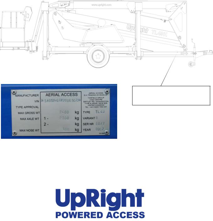
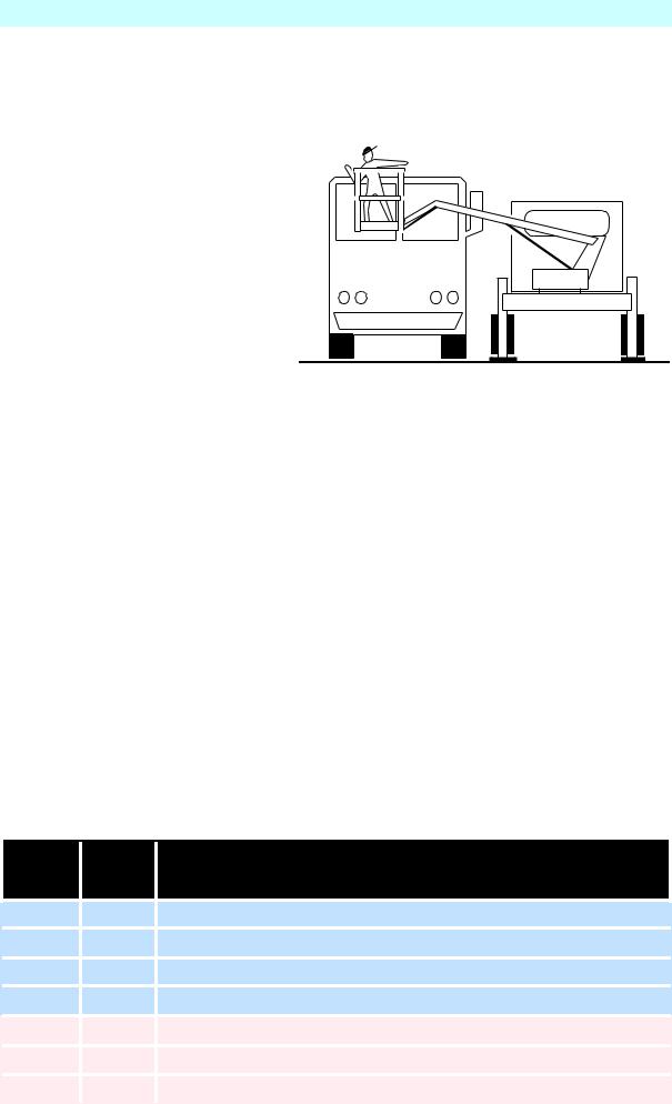
When contacting UpRight for service or parts information, be sure to include the MODEL and SERIAL NUMBERS from the equipment nameplate. Should the nameplate be missing, the SERIAL NUMBER is also stamped on top of the chassis bhind the toe hitch.
Serial number stamped on chassis behind the toe hitch and above the Vehical Identification Number Plate.
www.upright.com
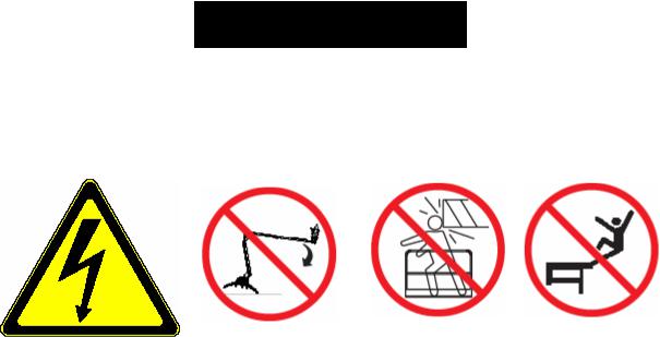
! WARNING !
Safety Rules
All personnel shall carefully read, understand and follow all safety rules and operating instructions before operating or performing maintenance on any UpRight aerial work platform
Electrocution Hazard |
Tip Over Hazard |
Collision Hazard |
Fall Hazard |
This Machine is NOT Insulated
NEVER elevate the platform or drive the machine while elevated unless the
machine is on a firm, level surface.
NEVER position the platform |
NEVER climb, stand, or sit on |
without first checking for overhead |
platform guardrails or midrail. |
obstructions or other hazards. |
|
USE OF THE AERIAL WORK PLATFORM: This aerial work platform is intended to lift persons and his tools as well as the material used for the job. It is designed for repair and assembly jobs and assignments at overhead workplaces (ceilings, cranes, roof structures, buildings etc.). All other uses of the aerial work platform are prohibited!
THIS AERIAL WORK PLATFORM IS NOT INSULATED! For this reason it is imperative to keep a safe distance from live parts of electrical equipment!
Exceeding the specified permissible maximum load is prohibited! See “Special Limitations” for details.
The use and operation of the aerial work platform as a lifting tool or a crane (lifting of loads from below upwards or from up high on down) is prohibited!
NEVER exceed the manual force allowed for this machine. See “Special Limitations” for details.
DISTRIBUTE all platform loads evenly on the platform.
NEVER operate the machine without first surveying the work area for surface hazards such as holes, drop-offs, bumps, curbs, or debris; and avoiding them.
OPERATE machine only on surfaces capable of supporting wheel loads.
NEVER operate the machine when wind speeds exceed this machine’s wind rating. See “Beaufort Scale” for details.
IN CASE OF EMERGENCY push EMERGENCY STOP switch to deactivate all powered functions.
IF ALARM SOUNDS while platform is elevated, STOP, carefully lower platform. Move machine to a firm, level surface.
Climbing up the railing of the platform, standing on or stepping from the platform onto buildings, steel or prefab concrete structures, etc., is prohibited!
Dismantling the swing gate or other railing components is prohibited! Always make certain that the swing gate is closed and securely locked!
It is prohibited to keep the swing gate in an open position (held open with tie-straps) when the platform is raised! To extend the height or the range by placing of ladders, scaffolds or similar devices on the platform is prohibited! NEVER perform service on machine while platform is elevated without blocking elevating assembly.
INSPECT the machine thoroughly for cracked welds, loose or missing hardware, hydraulic leaks, loose wire connections, and damaged cables or hoses before using.
VERIFY that all labels are in place and legible before using.
NEVER use a machine that is damaged, not functioning properly, or has damaged or missing labels.
To bypass any safety equipment is prohibited and presents a danger for the persons on the aerial work platform and in its working range.
NEVER charge batteries near sparks or open flame. Charging batteries emit explosive hydrogen gas. Modifications to the aerial work platform are prohibited or permissible only at the approval by UpRight.
AFTER USE, secure the work platform from unauthorized use by turning both keyswitches off and removing key.
TL49K |
508159-000 |

CONTENTS
|
Page |
Introduction |
3 |
Description of Equipment |
4 |
Technical Specification |
5 |
Working Envelope |
6 |
Operator Requirements |
7 |
Warning Notices |
8 |
. Beaufort Scale |
9 |
Towing Instructions |
10 |
Hand Manoeuvring (Friction Drive Option) |
12 |
Pre-Start Checks |
13 |
Power Supply |
19 |
Batteries, & Power Pack |
15 |
Setting Up |
16 |
Extending Structure |
18 |
. Basket Controls |
18 |
. Ground Controls |
20 |
Safety Harness |
21 |
Emergency Controls |
|
. Emergency Stops |
21 |
. Emergency Lower (Electronically) |
22 |
. Emergency Lower (Manually) |
23 |
. Emergency Raise Outriggers |
24 |
. Emergency Cage Overload |
24 |
. Emergency Battery Isolation |
25 |
Stowing the Machine |
26 |
Maintenance |
|
. Daily Checks |
27 |
. Weekly and Monthly Checks |
28 |
. Slew Drive and Limit Switches |
29 |
. Trailer Lighting Diagram |
30 |
Appendices |
|
Petrol/Bi-fuel Option. |
31 |
Generator Option. |
32 |
Mains connection. |
33 |
2 |
508159-000 |
TL49K |

INTRODUCTION
The UpRight TL49K is a class leader, offering several features as standard that other manufacturers only provide as optional extras.
These include powered basket rotation and fully proportional hydraulic controls, at both basket and ground level.
The third flick boom, with 130 DEGREES working arc, guarantees access to the most hard to reach places, while the 90 DEGREES basket rotation provides the precision positioning that is vital for working in tight spaces.
UpRight Powered Access has a global reputation for innovation and a proud heritage in the design and manufacture of high quality powered access equipment.
The company was founded in the UK more than 25 years ago, on the principle of constantly improving service excellence for end users.
Every model in our growing range of versatile, trailer mounted units is a class leader and together they have set new industry benchmarks.
Our commitment to research and design, plus 250,000sq ft of same site fabrication, build and support capacity, mean UpRight can offer complete solutions to meet even the most demanding access applications.
UpRight has third party accreditation to quality standard ISO 9001 and the full range carries the CE mark, complying with or exceeding all relevant standards and EC directives.
UpRight Powered Access is a member of the
International Powered Access Federation (IPAF).
To ensure you are fully aware of safety and operational information, the following symbols are used throughout this manual;
This type of box contains, Points of operation to NOTE.
!text. It gives Warnings about the risk of Damage to equipment, and possibly personnel.The information contained in this type of box contains, WARNING
The information contained in this type of box contains, DANGER
1text. It gives Warnings about the risk of PERSONAL INJURY to the operator and or others.
TL49K |
508159-000 |
3 |

DESCRIPTION OF EQUIPMENT
The UpRight TL49K is of the parallel linkage vertical boom design, mounted on a road towable trailer. The unique, yet very simple boom configuration gives the maximum safety and control ability combined with a robust construction to withstand a heavy working environment
The TL49K machine is designed for two man capacity (200 kg S.W.L.).
The machine incorporates a bottom boom with tie-rod, a short vertical boom and a top boom with a telescope section. The TL49K also has an independent hydraulically operated flick-out boom and rotating cage for extra manoeuvrability.
The hydraulic system is of a failsafe design throughout, with built in hydraulic lock valves on all of the rams as a precaution against hose failure. The machine is controlled by means of proportional manual controls of the ‘direct hand’ lever operating type. These valves are located at both the base and in the cage, as standard.
Electrically operated emergency lowering valves are fitted as standard to allow the machine to be lowered from the base and basket.
The hydraulically operated outriggers are fitted with load sensing interlocks, to prevent the booms from being raised without the outriggers being extended and under load. An interlock prevents the hydraulic outriggers being accidentally retracted while the booms are raised. A simple system of warning lights show the power supply is on and each of the outriggers is under load.
Performance. |
|
Maximum Working Height |
17.00 m |
Maximum Working Outreach: |
9.10 m |
Capacity (2 man working): |
200 kg |
Slewing Arc: |
680° |
Airborne Noise Emissions (Battery): |
70 dB(A) |
Construction Standards.
The machine complies fully with the requirements of the following EEC Directives: Directive 98/37/EC – the ‘Machinery Directive’.
Directive 89/336/EEC – the ‘Electromagnetic Compatibility Directive’. Directive 73/23/EEC – the ‘Low Voltage Directive’.
EN 6020-1/1993 ‘Safety of Machinery.’
The machine is designed and tested in accordance with all relevant B.S.I and European Standards including EN280.
4 |
508159-000 |
TL49K |
|
|
TECHNICAL SPECIFICATION |
|
Cage Dimensions |
|
|
|
Length |
|
1.20m |
|
Width |
|
0.80m |
|
Guard-rail Height |
1.10m |
|
|
Toe-board Height |
0.15m |
|
|
Operating Dimensions |
|
|
|
Maximum Working Height |
17.00m |
|
|
Maximum Cage Height |
15.00m |
|
|
Maximum Outreach ( From centre of rotation ) |
9.10m |
|
|
Travel Dimensions |
|
|
|
Towing Length |
7.10m |
|
|
Closed Width |
|
1.75m |
|
Closed Height |
2.10m |
|
|
Weight |
(Battery Model) |
2250 kg (un-laden) |
|
|
(Battery Model + Friction Drive) |
2395 kg (un-laden) |
|
|
(Bi-fuel Model) |
2300 kg (un-laden) |
|
Operating Parameters |
|
|
|
Safe Working Load |
200 kg |
|
|
Maximum Horizontal Pull |
400N |
|
|
Maximum Wind Speed |
12.5 ms-1 |
|
|
Rotation |
|
680° |
|
Cage Slew |
|
90° |
|
Equipment |
|
|
|
Bottom Ram |
|
Double acting: |
Bore Ø 80.0 mm |
|
|
|
Rod Ø 50.0 mm |
Top Ram |
|
Double acting: |
Bore Ø 80.0 mm |
|
|
|
Rod Ø 50.0 mm |
Tele’ Ram |
|
Double acting: |
Bore Ø 65.0 mm |
|
|
|
Rod Ø 45.0 mm |
Flick Ram |
|
Double acting: |
Bore Ø 60.0 mm |
|
|
|
Rod Ø 40.0 mm |
Stabiliser Ram |
Double acting: |
Bore Ø 70.0 mm |
|
|
|
|
Rod Ø 40.0 mm |
Bottom & Top Ram Lock Valves |
Pilot operated over centre valves |
||
Control Valve (Cage) |
Monoblock unit consisting of seven |
||
|
|
double acting spools |
|
Control Valve (Ground) |
Monoblock unit consisting of five |
||
|
|
double acting spools |
|
Control Valve (Stabiliser) |
Monoblock unit consisting of four |
||
|
|
double acting spools |
|
Bushes |
|
Acetol resin polymer with sintered |
|
|
|
bronze base (DX) |
|
Pivot Pins |
|
Stainless Steel Bright Bar |
|
|
|
To Grade BS970 303 S31 CW, & |
|
|
|
MecaVal 147m, Tuftride TFI-AB1 |
|
|
|
coated. |
|
TL49K |
508159-000 |
5 |
|
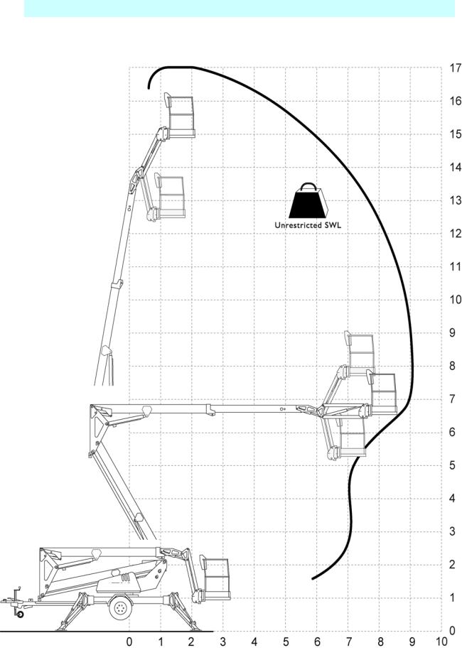
OPERATING ENVELOPE
200kg
Height and Distance in Metres.
6 |
508159-000 |
TL49K |
OPERATOR REQUIREMENTS
Please read this carefully, and ensure you have received the correct training prior to operating this machine.
1.To operate the machine you must be medically fit and have no problems with eyesight or hearing.
2.You must have a good head for heights.
3.Your primary concern must be the safe operation of the work platform, the safety of the people working with you, and the safety of other persons in your working area.
4.You must be familiar with the contents of this manual, and at no time attempt to operate the machine beyond the recommended limits.
5.The proper care of the work platform is a major factor in ensuring the safety of those who work with it.
6.You must not misuse the machine or ignore or interfere with the devices that have been provided to maintain safety.
7.Operation of the machine should be restricted to personnel who have been authorised to operate the equipment and have received proper training.
TL49K |
508159-000 |
7 |
WARNING NOTICES
1.DO NOT operate this machine unless you have been fully trained in its safe use.
2.DO NOT operate the machine on soft, slippery or sloping ground unless adequate precautions have been taken.
The stabilisers are designed to operate on firm level ground with a minimum bearing strength of 50N/cm2.
The maximum load imposed by an outrigger is 12.5kN.
Advice should be obtained from UpRight as to the type of supports and precautions required before attempting to operate the machine outside these parameters.
3.DO NOT use any equipment in the basket to increase the reach or working height of the machine, e.g. ladders.
4.DO NOT fit any additional equipment to the machine that would increase the wind loading, e.g. notice boards.
5.DO NOT use the machine for any application that may produce special loads or forces: the manufacturer, UpRight Powered Access, must be consulted for approval of special applications prior to use.
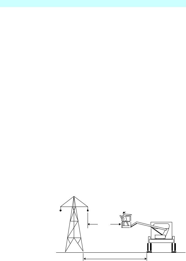
6.DO NOT use the machine close to live electrical conductors. The minimum safe working distance for a machine working near overhead power cables is the maximum extended length of the booms plus 15 metres, measured with the booms pointing towards the lines, i.e. safe working distance for the TL49K is 24 metres. It is the operator‘s responsibility to ensure that, when working in the vicinity of live overhead high-voltage lines, the minimum safe working distance is maintained. Erect a simple barrier tape at the safe distance.
15m
24m26m
7.WORKING CLOSE TO POWER CABLES – if work has to be carried out at less than the safe working distance, the operator must ensure that the electricity supply has been switched off. Before commencing work, a written permit to work must be obtained from the owners of the power cables or the responsible authority.
8 |
508159-000 |
TL49K |
WARNING NOTICES
8.DO NOT operate the machine unless all four outriggers are down and in full contact with the ground. The machine must be level and the wheels lifted visibly clear of the surface before the booms are raised.
9. DO NOT move the machine with the basket raised and never allow cage or booms to slew into the path of oncoming vehicles.
10. DO NOT operate the machine if the wind speed exceeds 12.5 m/s. Be aware that, when working near high buildings or structures, shielding and funnelling effects may cause high wind forces on days when the nominal wind speed in the open is low. Wind speed can either be measured from the work platform with a hand held anemometer or estimated using the Beaufort Scale.
BEAUFORT WIND SPEED SCALE
The Beaufort Scale of wind force is accepted internationally and is used in communicating weather conditions. It consists of numbers 0 - 12, each representing a certain strength of velocity of wind at 10m(33ft.)aboveground in the open.
Approximate corrections for wind speeds at other heights are:
|
|
2m subtract 30%; |
|
|
|
3m subtract 20%; |
|
|
|
6m subtract 10% |
|
|
|
15m add 10%; |
|
|
|
30m add 25% |
|
|
|
|
|
Beaufort |
M/Sec |
GroundConditions |
|
Scale |
|
|
|
|
3.5-5 |
Leaves and small twigs in constant motion; wind extends light flag. |
|
3 |
|
||
4 |
6-8 |
Raises dust and loose paper; small branches are moved. |
|
5 |
9-10 |
Small trees in leaf begin to sway; crested wavelets on inland waterways. |
|
6 |
11-13 |
Large branches in motion; umbrellas used with difficulty. |
|
7 |
14-17 |
Whole trees in motion; inconvenience felt when walking against wind. |
|
8 |
18-21 |
Breaks twigs off trees; generally impedes progress. |
|
9 |
22-24 |
Slight structural damage occurs (chimney pots and slates removed) |
|
|
|
|
|
TL49K |
508159-000 |
9 |

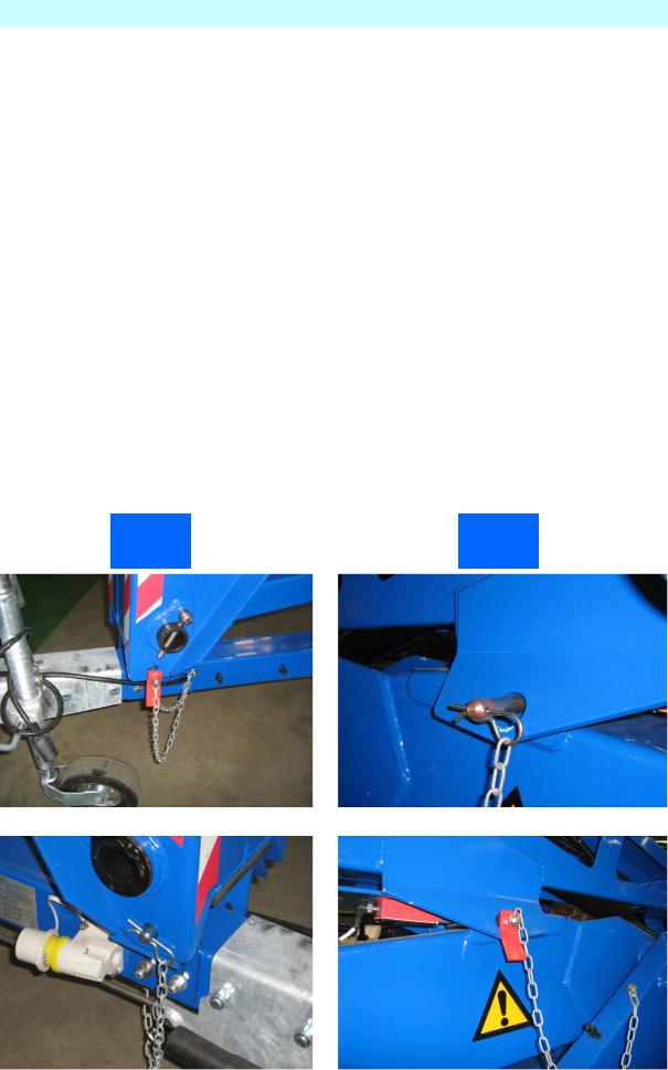
TOWING INSTRUCTIONS
Trailer mounted machines are fitted with suspension units that may be safely towed behind a car or van at speeds of up 50mph (80km/h) where permitted.
1.Before towing, check the capacity of the vehicle being used. (Machine weight will increase if optional extras are fitted)
2.Ensure that the road tyres and brakes are in good, serviceable condition.
3.Ensure that all booms are fully lowered and both the transit pins are fitted through the loops and secured with the “R” clip on the end of the chain.
L4 |
UpRight |
10 |
508159-000 |
TL49K |

TOWING INSTRUCTIONS
4.Ensure that all outriggers are fully raised.
L4 |
UpRight |
5.Use the Jockey Wheel to raise or lower the tow bar coupling to position the machine above the 50mm ball hitch on the towing vehicle.
6 |
7 |
|
11
8
9
6. |
Apply the handbrake. |
7.Lower the tow bar coupling down onto the ball hitch using the Jockey Wheel
8.Secure the breakaway cable,
(Ensure correct engagement of 50mm ball).
9. |
Fully raise the Jockey Wheel and lock in position. |
10. Release the Handbrake.
11.Plug in the trailer lights (7 pin plug) and check that both vehicle and trailer lights operate correctly.
TL49K |
508159-000 |
11 |

HAND MANOEUVERING (Optional)
1.Ensure that the booms are fully lowered, all outriggers are fully raised and the machine is in a menoeverable condition.
2.Engage the the friction drive cylinders against the trailer tyres by pulling actuating levers forward and down until they lock overcentre.
3. |
Ensure the power selector switch is set to Base. |
4. Disengage the handbrake, and ensure that the Jockey wheel directional locking pin is removed
5.Traction is controlled via the 2 hydraulic levers on the R/H side of the chassis.
6.The left lever controls the left motor and the right lever the right.
Operating only the left lever forward will turn the machine right and the right lever will turn the machine left, operate both levers together for parallel drive.
7.When the machine is in position replace handbrake.
! |
Ensure friction drive cylinders are disengaged prior to platform |
|
operation or towing. |
||
|
12 |
508159-000 |
TL49K |

PRE-START CHECKS
The following Pre-Start Checks should be carried out before taking the machine to the place of work.
L4 |
UpRight |
1.Damaged or Loose Fittings.
Visually Inspect the machine for signs of wear and tear, damage, loose or missing parts.
2.Wheels. (For towing only)
Check tyres are at the correct pressure, TL49K = 76psi (5.25 bar).
3.Hydraulic fluid.
The hydraulic oil tank is located underneath the slew cover on the right hand side of the machine (looking from the cage end), Ref, Fig.2, section J With the booms and outriggers in the transport position, the hydraulic oil
level should be visible between the upper and lower marks of the Sight Glass.
Top up with ISO Grade 22 hydraulic oil if necessary.
Do Not Overfill the Tank
Serious injury or even death may result by not carrying out the following checks of the interlock system before the platform is 1 used!
4.Safety Switches.
Visually check the cage overload switch is free from damage.
Check all limit switch arms are free from damage and move easily (outrigger switches shown in Fig.6 ).
With outriggers in transport position, it must not be possible to operate the extending structure. With outriggers deployed, under load and top or bottom boom raised approximately 50mm, it must not be possible to operate the outrigger controls.
The flick boom is not interlocked with the outriggers.
TL49K |
508159-000 |
13 |

PRE-START CHECKS
5.Emergency Stop Switches.
Emergency stop switches must operate correctly. Check that each stops the machine’s controls and that restarting is prevented until all stop switches are unlatched.
6.Emergency Lower/Slew.
With the top and bottom booms raised approximately 500mm each and the unit switched off, check:
The emergency lower switch located in the basket and ground control
stations, lowers the booms when operated.
The emergency slew, telescopic boom retraction can be operated by using the hand pump and control lever at the ground control station.
To Reset the hydraulic system after checks;
Fully slew the Basket to the right, so that he ram is fully extended.
Fully extend the Outriggers while still maintaining Level. (check the bubble) Using the ground controls, fully extend Top, Bottom and Telescopic Booms. Fully extend the Flick Out Boom.
All rams must be fully extended at the same time before returning them to their transit position.
If the Emergency Lower is used during normal operation, DO NOT use the machine, Contact your local UpRight representative.
7.Emergency Hand Pump.
With the unit set up for working (i.e. outriggers down, under load and the machine level with wheels clear of ground) it is possible to lower the cage using the emergency hand pump.
8.Battery Power (Where applicable)
Check batteries are fully charged and topped up with distilled water (these are fitted under the slew cover on both sides of the platform).
Hydrometer reading should be 1280-1320sg.
With machine level, the distilled water should cover the plates by approximately 6mm.
9.Mains Power (Where applicable)
Check that the voltage and frequency of the power input matches that of the motor. All extensions must be a minimum of 2.5mm², and no longer than 10m due to possible voltage drop.
10.Petrol/diesel Power (Where applicable)
Check that there is sufficient oil and fuel to complete a full working shift.
14 |
508159-000 |
TL49K |

BATTERIES & POWER PACK
Battery Power, 24V DC.
Ensure batteries have been fully charged before use and that the Battery Isolating Plug is securely connected.
Mains Power, (OPTIONAL)
Connect the mains supply, either 110V or 220/240V A.C., depending upon the motor specification. Check the motor is running when the key is turned to the ON position.
All extensions must be a minimum of 2.5mm², and no longer than |
! |
|
10m, due to possible voltage drop, which will damage the motor. |
||
|
Petrol/diesel Power, (OPTIONAL)
Check the fuel and oil levels of the engine. Switch on the ignition using the key switch on the slew mounted legend panel. Check the engine runs using the start and stop buttons in the basket.
Batteries |
|
|
|
Battery Charger |
|
|
|
|
Fig. 1
|
Power Pack |
|
Oil Filler and Sight Glass |
|
|
|
|
|
|
|
|
||
Fig. 2 |
|
|
|
|
|
|
|
|
|
|
|
|
Pump Handle |
Hand Pump
TL49K |
508159-000 |
15 |

SETTING UP
1. Park the unit in an appropriate location at the workplace.
Do not attempt to set up the machine on steep slopes, ramps or |
1 |
|
soft ground. |
||
|
2. Apply the handbrake on the trailer and remove from the towing vehicle.
Ground
3. With platform key switch set to ’Ground’ (Fig 3)
Basket
lower the outriggers by keeping the ‘Outrigger Motor Run’ button (Fig 4) pushed in, operate the appropriate ‘Outrigger control lever’ (Fig 5), until all four are 25mm to 50mm from the ground.
Fig. 3
Control Levers
Ground
Fig. 4
|
|
|
|
|
|
|
|
|
|
|
|
|
|
|
|
|
|
|
|
|
|
|
|
|
|
|
|
Motor Run |
|
|||
|
|
|
|
|
|
Outrigger |
|
|||
|
|
|
|
|
|
|
|
|
|
|
|
|
|
|
|
|
|
|
|
|
|
|
|
|
|
|
|
|
|
|
Motor Run |
|
|
Level |
|
|
|
|
|
|
|
||
|
|
|
|
|
|
|
Booms |
|||
indicator |
|
|
|
|
|
|
|
|
||
Fig. 5 |
|
|
|
|
|
|
||||
|
|
|
|
|
|
|||||
|
|
|
|
|
||||||
|
|
|
|
|
|
|
|
|
|
|
|
Control Levers |
|
|
|
|
|
|
|
|
|
|
Outriggers |
|
|
|
|
|
|
|
|
|
|
|
|
|
|
|
|
|
|
|
|
Emergency
Lower
16 |
508159-000 |
TL49K |
SETTING UP
4.Lower the Outriggers two at a time starting at the tow bar end (No’s 3&4) until the jockey wheel just clears the ground.
5.Lower Outriggers 1&2 until the green LED display indicates that they are under load. (As shown below)
!Jockey Wheel during the next step.
6.Repeat this sequence for Outriggers 3&4.
7.By alternating from 1&2 to 3&4, carefully inch down each pair of Outriggers until all four Outriggers are fully deployed, and the wheels are well clear of the ground.
8.Now, by using the Level indicator (Fig.5), raise opposite Outriggers until the bubble and indicator ring are concentric (i.e., the bubble rests in the centre).
9.Check that each LED on the Ground Control panel is still illuminated. This indicates that each foot is in firm contact with the supporting surface.Take EXTREME care NOT to ground either the Basket, or the
1The unit is designed to operate on a supporting surface of minimum bearing strength of 50N/cm2.
1The maximum outrigger load is 12.5kN.
TL49K |
508159-000 |
17 |
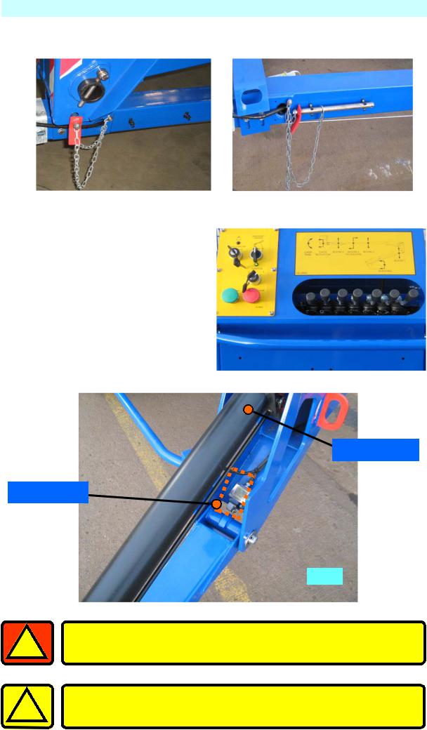
EXTENDING STRUCTURE
1.Remove and correctly stow the Transit Pins, from both the Upper and Lower Booms.
2.At the Ground Control Station, turn the key to ‘Basket’. (See Fig. 3)
3.Climb into the basket. Check that all Emergency Stop Switches are released (twist release). The platform may now be raised, lowered or slewed in any direction by operating the control levers at the basket, whilst depressing the motor run button (DEADMAN).
Outrigger Ram
Limit Switch
Fig. 6
1 |
Before raising, ensure there are no overhead obstructions or |
power cables and the outriggers are properly extended and |
|
secure. |
Take EXTREME care when slewing both basket and turret, at low ! levels.
18 |
508159-000 |
TL49K |

|
|
|
|
|
|
|
|
EXTENDING STRUCTURE |
||
|
|
|
|
|
|
|
|
|
|
|
|
|
|
|
|
Outrigger Load |
|
|
Basket overload |
|
|
|
Emergency Stop |
|
|
|
||||||
|
|
Indicators |
|
|
Indicator |
|
||||
|
|
|
|
|
|
|
|
|
|
|
|
|
|
|
|
|
|
Fig. 4a |
|
|
|
|
|
|
|
|
|
|
|
|
|
|
|
|
|
|
|
|
|
|
|
|
|
|
|
|
|
|
|
|
|
|
|
|
|
|
Control |
|
Motor Run |
|
|
|
|
|
|
|
|
|
|
|
Motor Run |
|
Emergency |
|
|||||
|
Selector |
|
|
|
|
||||||
|
|
Outriggers |
|
Booms |
|
Lower |
|
||||
|
|
|
|
|
|
|
|
|
|
|
|
4. |
Explanation of the Basket Control Station, Directional Control Levers. |
||||||||||
CAGE |
CAGE |
BOOM 3 |
BOOM 2 |
BOOM 2 |
|
|
TRIM |
ROTATION |
|
TELESCOPE |
|
|
|
|
|
|
|
|
BOOM 1 |
|
18-0865-02 |
|
|
|
|
SLEWING |
|
|
|
|
|
|
|
|
Raise |
Slew |
Raise |
Retract |
Raise |
Slew |
Raise |
Basket |
Basket |
Flick |
Tele- |
Tele- |
Turret |
Lower |
Trim |
Anticlockwise |
Boom |
Boom |
Boom |
Anticlockwise |
Boom |
|
Lower |
|
Slew |
|
Lower |
|
Extend |
|
Lower |
|
Slew |
|
Lower |
|
|
Basket |
|
Basket |
|
Flick |
|
Tele- |
|
Tele- |
|
Turret |
|
Lower |
|
|
Trim |
|
Clockwise |
|
Boom |
|
Boom |
|
Boom |
|
Clockwise |
|
Boom |
|
|
|
|
|
|
|
|
|
|
|
|
|
|
|
|
TL49K |
|
|
|
508159-000 |
|
|
|
19 |
||||||
EXTENDING STRUCTURE
5. A duplicate set of controls (excluding Slew Basket) is mounted on the Slew Turret under the right hand side cover, which allows the platform to be operated from the Ground.
6. At the Ground Control Station, turn the key to ‘Ground’. (See Fig.3)
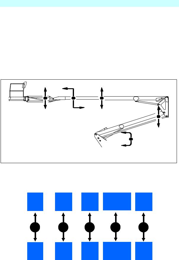
7. Explanation of the Ground Control Station, Directional Control Levers
B O O M 3 B O O M 2 B O O M 2
T E L E SC O P E
B O O M 1
SL E W IN G
18 - 0 8 8 4
Raise |
|
Extend |
|
Raise |
|
Slew |
|
Raise |
Flick |
|
Tele- |
|
Tele- |
|
Turret |
|
Lower |
Boom |
|
Boom |
|
Boom |
|
Anticlockwise |
|
Boom |
|
|
|
|
|
|
|
|
|
Lower |
|
Retract |
|
Lower |
|
Slew |
|
Lower |
Flick |
|
Tele- |
|
Tele- |
|
Turret |
|
Lower |
Boom |
|
Boom |
|
Boom |
|
Clockwise |
|
Boom |
|
|
|
|
|
|
|
|
|
20 |
508159-000 |
TL49K |
SAFETY
Safety Harness
1.In accordance with IPAF recommendations, UpRight recommend the use of a Full Body Harness with an adjustable lanyard is used when operation from the basket.
2.The lanyard length should be as short as possible.
3.A permanent attachment point is provided in the basket for fixing the harness.
L4 |
UpRight |
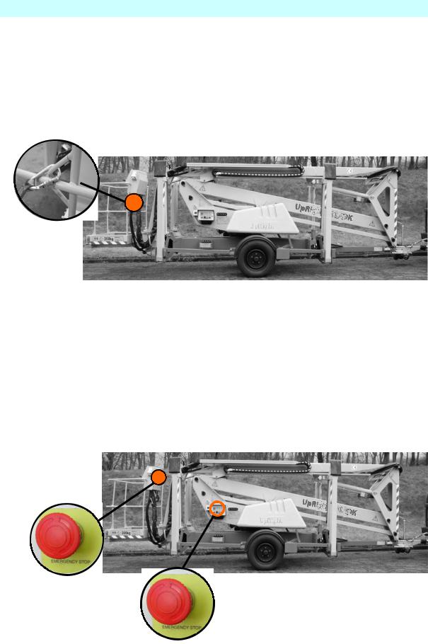
EMERGENCY CONTROLS
1. Emergency Stop
Emergency Stop buttons are fitted on the machine to stop the motor in an emergency.
There are 2 Emergency Stop Buttons, one in the basket, and one on the ground control panel.
L4 |
UpRight |
The emergency stops are ‘Reset’ by twisting.
TL49K |
508159-000 |
21 |
EMERGENCY CONTROLS
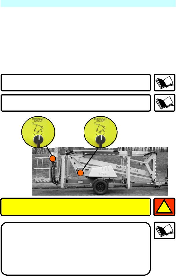
Emergency Lower.
In the event of a power failure, There are two ways of Safely lowering the basket.
2.Emergency Lowering, method one
The operator or someone on the ground, can lower the booms to a safe position by activating the Emergency lowering selector switch both ways, o n the Basket Control Panel and the Ground Control Panel.
The Flick Boom cannot be lowered by activating the Emergency Lowering Switch.
The Emergency lowering valve will automatically close when the switch is released.
L4 |
UpRight |
If the Emergency Lower is used due to a machine defect, DO NOT use |
1 |
|
the machine, Contact your local UpRight representative. |
||
|
If the Emergency Lower is used, The TOP and BOTTOM BOOMS must be fully extended then fully lowered before work can continue.
After Emergency lowering, any further POWERED lowering could cause an AIRLOCK in the hydraulic system.
This could cause the Hydraulic operations to Fail.
ALL BOOMS MUST BE FULLY EXTENDED/RAISED, THEN LOWERED BEFORE WORK CAN RECOMMENCE.
22 |
508159-000 |
TL49K |

EMERGENCY CONTROLS
3.Emergency Lowering a, method two.
You can operate the hand pump from the ground control station cage and operate the boom controls and slewing functions.
To operate the hand pump, insert the lever over the pump shaft, then lower the lever to a convenient position to start pumping.
Move a control lever to the required direction of movement, and operate the hand pump. When the machine starts to lower, continue depressing the control lever.
Vigorous pumping is required to lower and slew the machine.
TL49K |
508159-000 |
23 |
EMERGENCY CONTROLS
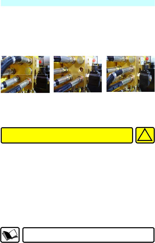
4.Emergency Procedure, Manual Raising of Outriggers.
In the event of power failure, the outriggers can be raised to their transport position.
First the hand pump hose fitted to port HP1, must be redirected from HP1, to port HP2, and the blanking plug from HP2 must be replaced into HP1, using a 22mm spanner.
Once connected, move an Outrigger Control Lever in the required direction of movement, and operate the hand pump. When the Outrigger starts to raise, continue depressing the control lever.
Some hydraulic oil will be lost during this procedure. This will |
! |
still allow Emergency operations, but will need to be replaced |
|
before full normal use can resumed. |
5. Cage Overload
In the event of the cage being overloaded, an audible alarm will sound and the cage controls will cut out.
To re-start, enough load must be removed from the cage so that the alarm stops sounding.
In cases where the overload can not be immediatley removed or the cage has fouled, then the overload override selector switch can be used to move the platform to a safe position so that the overload can safely removed.
The Key, Motor Run/Deadman and a Control Lever must be operated at the same time to effect this action
24 |
508159-000 |
TL49K |

EMERGENCY CONTROLS
L4 |
UpRight |
6. |
Emergency Battery Isolating Plug. |
|||||||||
|
Disconnecting this plug will isolate the batteries from the powerpack |
|||||||||
|
and operating circuits. |
|||||||||
|
|
|
|
|
|
|
|
|
|
|
|
|
|
|
|
|
|
|
|
|
|
|
|
|
|
|
|
|
|
|
|
|
Before operating this machine, it is important that both the Operator and another responsible person on site, is aware of the position and function of the following:
A)Emergency Stop Buttons.
B)Emergency Lowering Buttons.
C)Emergency Slew Drive Shaft.
D)Battery Isolating Plug.
TL49K |
508159-000 |
25 |
STOWING THE MACHINE
1. |
Fully lower all the booms. |
2. |
Engage the Transit Pins, and lock in place using ‘R’ clip. |
3. |
With platform keyswitch set to ‘Ground’: |
|
Raise the outriggers by simultaneously depressing the ‘MOTOR RUN |
Outrigger’ button and using the appropriate control levers, two at a time, alternating between the cage and tow bar end until the road wheels are in contact with the ground.
Only when the road wheels are in contact with the ground should the unit be lowered further until the jockey wheel makes contact with the supporting surface.
Now fully raise the outriggers until they are in the stowed position.
Switch off the platform and ensure all loose items/covers are secure before towing the unit.
The machine is now ready for transportation.
TRANSPORT PIN LOCATIONS – SHOWN READY FOR TRANSPORT
Lower |
Upper |
Boom |
Boom |
26 |
508159-000 |
TL49K |
Loading...