


AB60JRT
Operator Manual
Betriebsanleitung
Manual del Usuario
Manuale d’Uso
Bedieningshandleiding
Manual part number 508321-001(EN)
Bestellnummer 508321-001(DE)
El número de referencia para el manual es el 508321-001(ES)
Manuale Ricambi Numero 508321-001(IT)
Handboek onderdeelnummer 508321-001(NL)
September 08

Table of Contents
Table of Contents |
|
Declaration of Conformity........................................... |
2 |
Safety Rules ............................................................... |
3 |
Introduction................................................................. |
4 |
Component Identification............................................ |
4 |
Special Limitations...................................................... |
5 |
Platform Capacity.................................................... |
5 |
Manual Force .......................................................... |
5 |
Platform Overload Sensing System ........................ |
5 |
Beaufort Scale......................................................... |
5 |
Controls and Indicators............................................... |
6 |
Battery Disconnect Switch ...................................... |
6 |
Lower Controls and Indicators ................................ |
6 |
Upper Controls and Indicators ................................ |
6 |
Pre-Operation Safety Inspection ................................ |
7 |
System Function Inspection ....................................... |
8 |
Operation.................................................................... |
9 |
Cold Weather Start-Up ............................................ |
9 |
Hydraulic System Cold Weather Warm-Up ............ |
9 |
Hydraulic System Warm-up Switch ......................... |
9 |
Manually Warming The Hydraulic System .............. |
9 |
Preparing for Operation......................................... |
10 |
Lower Controls ...................................................... |
10 |
Upper Controls ...................................................... |
10 |
Boom Operation .................................................... |
10 |
Driving and Steering.............................................. |
10 |
Drive Speeds......................................................... |
11 |
Motion Warning Alarm ........................................... |
11 |
AC Generator ........................................................ |
11 |
Air Line .................................................................. |
12 |
Driving Lights ........................................................ |
12 |
Platform Work Lights ............................................. |
12 |
Emergency Lowering ............................................ |
12 |
Riser Boom ........................................................... |
12 |
Main Boom ............................................................ |
13 |
After Use Each Day............................................... |
13 |
Transporting the Machine......................................... |
14 |
Preparing for Transportation ................................. |
14 |
By Crane ............................................................... |
14 |
By Truck ................................................................ |
14 |
Maintenance............................................................. |
15 |
Hydraulic Fluid ...................................................... |
15 |
Check Hydraulic Fluid ........................................... |
15 |
Engine ................................................................... |
15 |
Oil Level ................................................................ |
15 |
Battery Maintenance ............................................. |
15 |
Inspection and Maintenance Schedule..................... |
16 |
Daily Preventative Maintenance Checklist ............... |
17 |
Preventative Maintenance Report......................... |
17 |
Decal Location.......................................................... |
18 |
Specifications ........................................................... |
20 |
Aerial Platform....................................................... |
20 |
Platform................................................................. |
20 |
Function Speed ..................................................... |
20 |
Drive System......................................................... |
20 |
Tires ...................................................................... |
20 |
Electrical System................................................... |
20 |
Hydraulic System .................................................. |
20 |
Engine ................................................................... |
20 |
Fuel Tank Capacity................................................ |
20 |
Ambient Air Temperature Operating Range .......... |
20 |
Maximum Wind Speed .......................................... |
20 |
Vibration ................................................................ |
20 |
Sound Threshold................................................... |
20 |
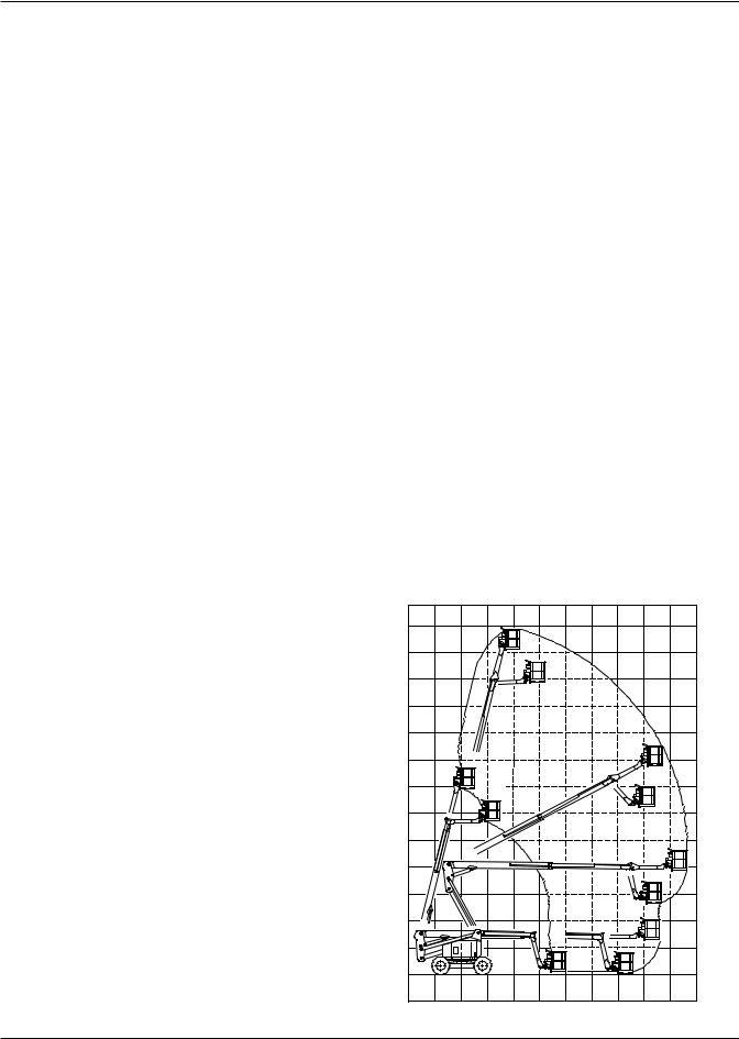
Working Envelope ................................................. |
20 |
AB60JRT |
1 |

EC DECLARATION OF CONFORMITY
FOR MACHINERY
MACHINERY:
Powered Aerial Platform known as:
Type: |
SNORKEL AB60J (Upright AB60JRT) |
Serial Number:
The machine specified above conforms to the following provisions:
Machinery directive 98/37/EC (using document EC Community Legislation on Machinery and taking guidance from EN280:2001 + Amendment A1:2004)
Council Directive 89/336/EEC on Electromagnetic Compatibility as amended by 93/68/EEC and 92/31/EC Council Directive 73/23/EEC on Low Voltage Equipment Safety as amended by 93/68/EE
Council Directive 2000/14/EC on Noise Emission in the Environment by Equipment for use Outdoors
As performed in accordance with EN 3744:1995
Measured sound power level |
91 dB |
Min |
|
100dB |
Max |
||
|
|||
|
|
|
|
Guaranteed sound power level |
100dB |
|
E. C. Type Examination Certificate No:
Note: Modification of the specified unit renders this declaration invalid
2 |
AB60JRT |

SAFETY RULES
AWarning
All personnel shall carefully read, understand and follow all safety rules and operating instructions before operating or performing maintenance on any UpRight aerial work platform.
Electrocution Hazard |
Tip Over Hazard |
Collision Hazard |
Fall Hazard |
|
8 |
|
|
|
3 |
|
|
|
B |
|
|
|
A |
|
|
|
t |
|
|
|
h |
|
|
|
g |
|
|
|
i |
|
|
|
R |
|
|
|
p |
|
|
|
U |
|
|
THIS MACHINE IS NOT INSULATED!
NEVER elevate the platform or drive the machine while elevated unless the machine is on a firm, level surface
NEVER position the platform without first checking for overhead obstructions or other hazards.
NEVER climb, stand, or sit on platform guardrails or midrail.
USE OF THE AERIAL WORK PLATFORM: This aerial work platform is intended to lift persons and his tools as well as the material used for the job. It is designed for repair and assembly jobs and assignments at overhead workplaces (ceilings, cranes, roof structures, buildings etc.). Uses or alterations to the aerial work platform must be approved by UpRight.
THIS AERIAL WORK PLATFORM IS NOT INSULATED! For this reason it is imperative to keep a safe distance from live parts of electrical equipment!
Exceeding the specified permissible maximum load is prohibited! See “Platform Capacity” on page 5 for details. The use and operation of the aerial work platform as a lifting tool or a crane is prohibited!
NEVER exceed the manual force allowed for this machine. See “Manual Force” on page 5 for details. DISTRIBUTE all platform loads evenly on the platform.
NEVER operate the machine without first surveying the work area for surface hazards such as holes, drop-offs, bumps, curbs, or debris; and avoiding them.
OPERATE machine only on surfaces capable of supporting wheel loads.
NEVER operate the machine when wind speeds exceed this machine’s wind rating. See “Beaufort Scale” on page 5 for details.
Do not operate the aerial platform in windy or gusty conditions. Do not add anything to the aerial platform that will increase the wind loading such as billboards, banners, flags, etc.
IN CASE OF EMERGENCY push EMERGENCY STOP switch to deactivate all powered functions.
IF ALARM SOUNDS while platform is elevated, STOP, carefully lower platform. Move machine to a firm, level surface.
Climbing up the railing of the platform, standing on or stepping from the platform onto buildings, steel or prefab concrete structures, etc., is prohibited!
Dismantling the entry gate or other railing components is prohibited! Always make certain that the entry gate is closed! It is prohibited to keep the entry gate in an open position when the platform is raised!
To extend the height or the range by placing of ladders, scaffolds or similar devices on the platform is prohibited! NEVER perform service on machine while platform is elevated without blocking elevating assembly.
INSPECT the machine thoroughly for cracked welds, loose or missing hardware, hydraulic leaks, loose wire connections, and damaged cables or hoses before using.
VERIFY that all labels are in place and legible before using.
NEVER use a machine that is damaged, not functioning properly, or has damaged or missing labels.
To bypass any safety equipment is prohibited and presents a danger for the persons on the aerial work platform and in its working range.
NEVER charge batteries near sparks or open flame. Charging batteries emit explosive hydrogen gas. Modifications to the aerial work platform are prohibited or permissible only at the approval by UpRight. AFTER USE, secure the work platform from unauthorized use by turning the keyswitch off and removing key. The driving of MEWP’s on the public highway is subject to national traffic regulations.
Certain inherent risks remain in the operation of this machine despite utilizing proper design practices and safeguarding.
Harness attachment points are provided in the platform and the manufacturer recommends the usage of a fall restraint harness, especially where required by national safety regulations.
Care must be taken to ensure that the machines meets the requirements of stability during use, transportation, assembly, dismantling when out of service, testing, or foreseeable breakdowns.
In the event of an accident or breakdown see “Emergency Lowering” on page 12, do not operate the aerial platform if it is damaged or not functioning properly. Qualified maintenance personnel must correct the problem before putting the aerial platform back into service.
AB60JRT |
3 |

Introduction
Introduction
This manual covers the AB60JRT Aerial Work Platform.
This manual must be stored on the machine at all times.
Read, Understand and follow all safety rules and operating instructions before attempting to operate the machine.
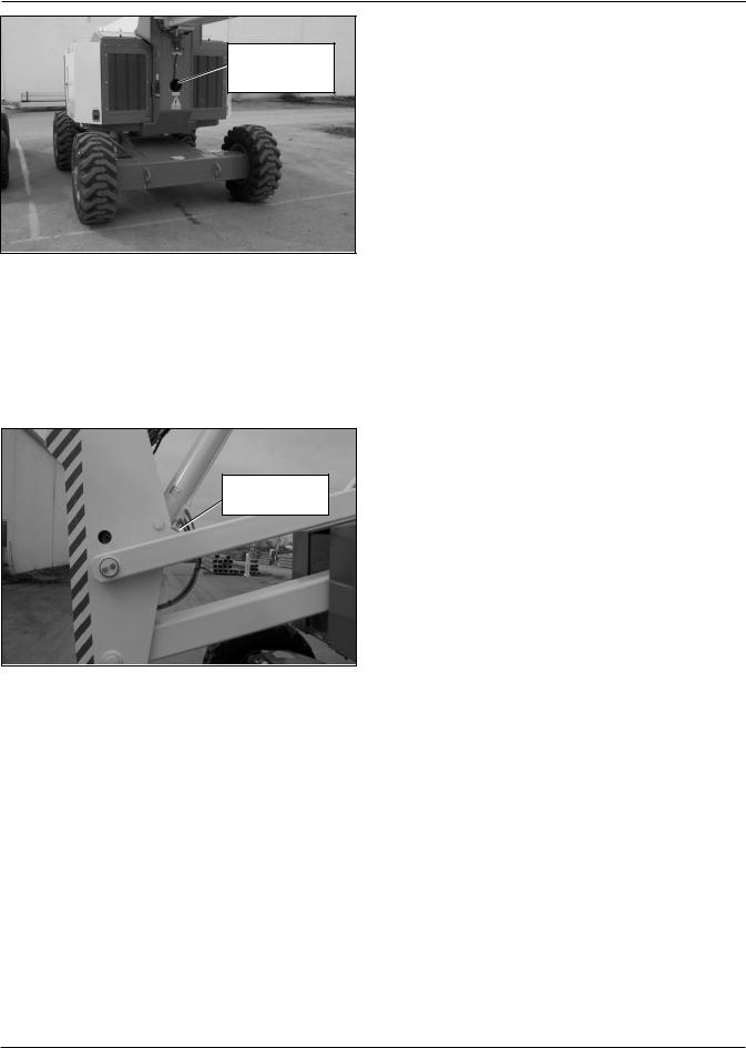
When contacting UpRight for service or parts information, be sure to include the MODEL and SERIAL NUMBERS from the equipment nameplate. Should the nameplate be missing, the SERIAL NUMBER is also stamped next to the right hand Rear Drive Motor Cover.
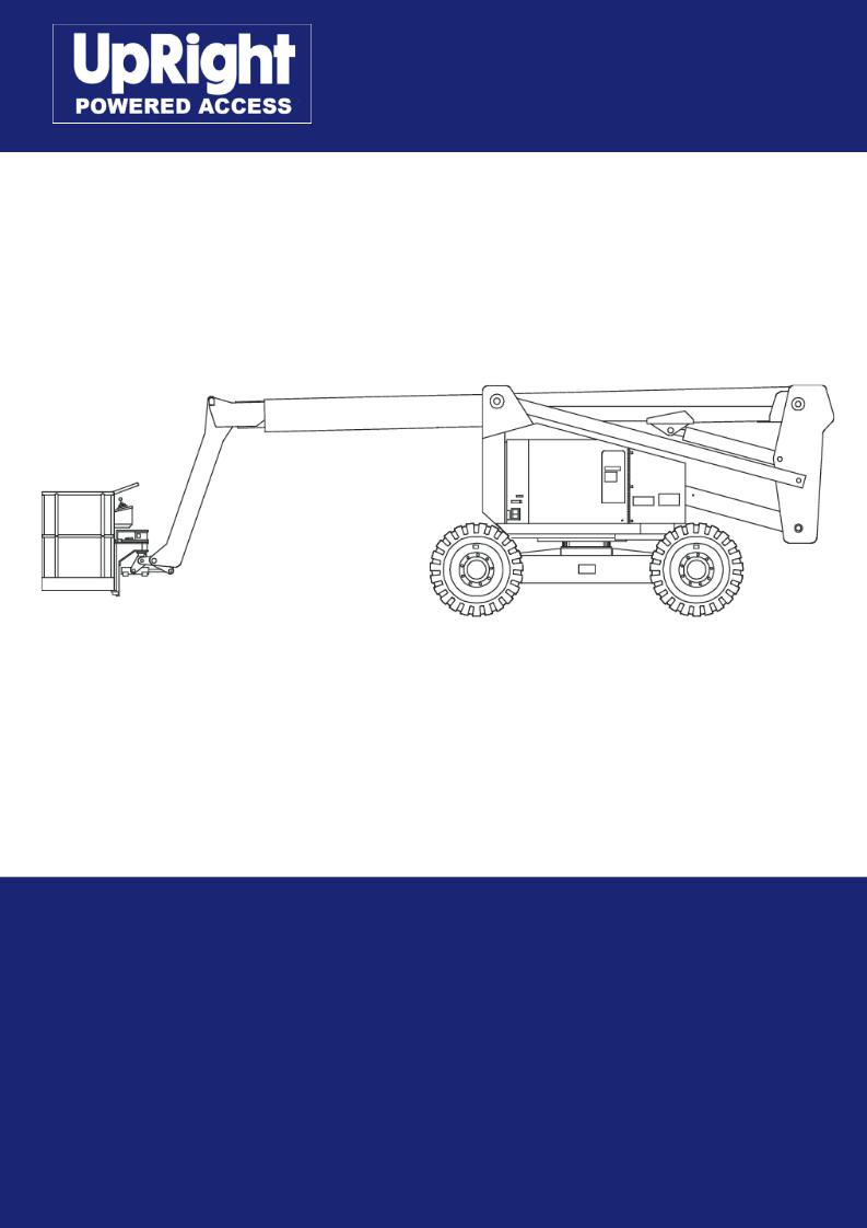
Component Identification
|
Hydraulic Fluid |
Emergency |
Fuel Tank |
Tank |
Lowering Valve |
|
|
Upper Controls
Emergency 
Lowering Valve
Hydraulic Fluid Chassis |
Steer Wheels |
Filter |
|
Right Side
|
|
|
Nameplate |
|
|
Battery Disconnect Switch |
Location |
|
|
|
|
Floating |
Lower |
Engine |
Main Boom |
Turret |
Controls |
Battery |
Tip Boom |
Platform
Operator’s
Manual
Jib
Boom
Riser
Boom
Steer Wheels
Platform
Foot Switch
Left Side
4 |
AB60JRT |

Special Limitations
Special Limitations
Travel with the platform raised is limited to creep speed range. Elevating the platform is limited to firm, level surfaces only.
ADanger
The elevating function shall ONLY be used when the work platform is level and on a firm surface.
The work platform is NOT intended to be driven over uneven, rough, or soft terrain.
Platform Capacity
Two people and tools may occupy the platform. The maximum platform capacity for the aerial platform is stated in the “Specifications” on page 20.
The system will remain in error mode until the excess load is removed from the platform and the emergency stop button or start switch is cycled off and back on, resetting the system. At that time, the machine functions are operational.
ACaution
The emergency power system is for emergency lowering and stowing only. The length of time the pump can be operated depends on the capacity of the battery. Do not use this system for normal operation.
If the platform overload sensing system is tripped while operating the machine or if the system is in error mode and can not be reset, the emergency power system may still be used for emergency machine operation.
ADanger
DO NOT exceed the maximum platform capacity or the platform occupancy limits for this machine.
Manual Force
Manual force is the force applied by the occupants to objects such as walls or other structures outside the work platform.
The maximum allowable manual force is limited to 200N (45 lbs) of force per occupant, with a maximum of 400 N (90 lbs) for two occupants.
ADanger
DO NOT exceed the maximum amount of manual force for this machine.
Platform Overload Sensing System
All functions are stopped from the upper and lower controls, when the platform overload limit is exceeded. The horn will sound intermittently and the platform overload light will blink until the excess load is removed from the platform. At that time, the machine functions are again
operational.
If the platform becomes significantly overloaded, or if an upward force on the platform exceeds approximately 2225 N (500 lbs), the system will enter into error mode, stopping all functions from the upper and lower controls. The horn will then sound constantly and the overload light will stay illuminated at the upper and lower controls.
ADanger
The aerial platform can tip over if it becomes unstable. Death or serious injury will result from a tip-over accident. Do not exceed the capacity values indicated on the platform rating placard.
The overload sensing system is not active when the machine is being driven with the booms in the stowed position. This allows the machine to be driven without the system sensing an overload due to rough ground conditions.
To eliminate repeated tripping of the system during machine operation, there is a five second delay in machine functions following:
•starting the engine.
•placing the drive/boom selector switch in the boom position when the main boom is below horizontal and fully retracted.
•removing excess load from the platform.
Beaufort Scale
Never operate the machine when wind speeds exceed 12.5 m/s (28mph) [Beaufort scale 6]. Refer to Figure 1.
BEAUFORT |
|
WIND SPEED |
|
GROUND CONDITIONS |
||
RATING |
m/s |
km/h |
ft/s |
mph |
||
|
||||||
3 |
3,4~5,4 |
12,25~19,4 |
11.5~17.75 |
7.5~12.0 |
Papers and thin branches move, flags wave. |
|
4 |
5,4~8,0 |
19,4~28,8 |
17.75~26.25 |
12.0~18 |
Dust is raised, paper whirls up, and small branches sway. |
|
5 |
8,0~10,8 |
28,8~38,9 |
26.25~35.5 |
18~24.25 |
Shrubs with leaves start swaying. Wave crests are apparent in ponds |
|
or swamps. |
||||||
|
|
|
|
|
||
6 |
10,8~13,9 |
38,9~50,0 |
35.5~45.5 |
24.5~31 |
Tree branches move. Power lines whistle. It is difficult to open an |
|
umbrella. |
||||||
|
|
|
|
|
||
7 |
13,9~17,2 |
50,0~61,9 |
45.5~56.5 |
31.~38.5 |
Whole trees sway. It is difficult to walk against the wind. |
|
Figure 1 – Beaufort Scale
AB60JRT |
5 |

Controls and Indicators
Controls and Indicators |
14. |
Engine/emergency power switch |
The operator shall know the location of each control and |
15. Throttle switch |
|
indicator and have a thorough knowledge of the function |
16. |
Hydraulic warm-up switch (option) |
and operation of each before attempting to operate the |
17. |
Circuit breaker reset buttons |
machine. |
18. |
Platform overload light |
|
19. |
Hour meter |
1 |
34 |
33 |
20 |
32 |
|
|
24 |
|
|
|
|
|
|
|
29 |
22 |
|
|
|
|
|
||
|
|
|
|
27 |
|
|
|
25 |
|
30 |
|
|
|
|
|
|
23 |
26 |
28 |
31 |
Figure 2 – Battery Disconnect Switch
1. Battery Disconnect Switch
7 |
8 |
|
10 |
3 |
9 |
12 |
13 |
|
11 |
6 |
|
|
2 |
14 |
|
16 |
|
|
|
|
|
|
|
5 |
|
|
18 |
4 |
|
|
|
|
|
19 |
15 |
17 |
|
|
|
|
|
|
|
Figure 3 – Lower Controls and Indicators
2.Emergency stop button
3.Control selector switch
4.Start switch
5.Ground operation switch
6.Rotation switch
7.Riser boom elevation switch
8.Main boom elevation switch
9.Boom extension switch
10.Jib articulation switch
11.Boom speed knob
12.Platform level switch
13.Platform rotate switch
35
36 |
21
Figure 4 – Upper Controls and Indicators
20.Emergency stop button
21.Start switch
22.Drive/boom selector switch
23.Boom joystick
24.Riser boom elevation switch
25.Boom extension switch
26.Jib articulation switch
27.Boom speed knob
28.Drive joystick
29.Drive range switch
30.Platform level switch
31.Platform rotate switch
32.Engine/emergency power switch
33.Throttle switch
34.Platform overload light
35.Machine/generator switch
6 |
AB60JRT |

Pre-Operation Safety Inspection
Pre-Operation Safety Inspection
Note
Carefully read, understand and follow all safety rules, operating instructions, labels and National Safety Instructions/Requirements. Perform the following steps each day before use.
1.Open the turntable covers and inspect for damage, fluid leaks or missing parts.
2.Check the level of the hydraulic fluid with the platform fully lowered. The fluid level must be between the full and add marks as viewed on the sight glass. Add recommended hydraulic fluid if necessary. See “Specifications” on page 20.
3.Check that the fluid level in the batteries is correct. See “Battery Maintenance” on page 15.
4.Check that all guardrails are in place and all fasteners are properly tightened.
5.Inspect the machine thoroughly for cracked welds and structural damage, loose or missing hardware, hydraulic leaks, damaged control cable and loose wire connections.
AB60JRT |
7 |

System Function Inspection
System Function Inspection |
5. Test each machine function (Lift, Slew, Telescope) |
Refer to “Controls and Indicators” on page 6 for the loca- |
from the lower control station by holding the ground |
tions of various controls and indicators. |
operation switch up while operating the control toggle |
|
switches (ref: Figure 3 on page 6). |
AWarning
STAND CLEAR of the work platform while performing the following checks.
Before operating the machine, survey the work area for surface hazards such as holes, drop-offs, bumps and debris.
Check in ALL directions, including above the work platform, for obstructions and electrical conductors.
1.Move the machine, if necessary, to an unobstructed area to allow for full elevation.
2.Pull the Lower Control Emergency Stop Switch to the ON position.
3.Pull the Upper Control Emergency Stop Switch to the ON position.
4.Visually inspect the elevating assembly, lift cylinder, cables, and hoses for cracked welds and structural damage, loose hardware, hydraulic leaks, loose wire connections, and erratic operation. Check for missing or loose parts.
6.Test the engine/emergency power switch for proper operation.
7.Push the Lower Control Emergency Stop Button to check for proper operation. All machine functions should be disabled. Pull the Lower Control Emergency Stop Button outward to resume.
8.Enter the platform and close the gate.
9.Check that the route is clear of obstacles (persons, obstructions, debris), is level, and is capable of supporting the wheel loads.
10.Test each machine function (Drive, Lift, Slew, Telescope, Platform Rotate, Platform Level) from the upper control station by stepping on the platform foot switch and operating the function controls (ref: Figure 4 on page 6).
11.Push the Upper Control Emergency Stop Button to check for proper operation. All machine functions should be disabled. Pull the Upper Control Emergency Stop Button outward to resume.
8 |
AB60JRT |
Operation
Operation
The aerial platform may be operated from either the lower or upper controls.
ADanger
The aerial platform is not electrically insulated. Death or serious injury will result from contact with, or inadequate clearance from, an energized conductor. Do not go closer than the minimum safe approach distance as defined by national safety regulations.
Pinch points may exist between moving components. Death or serious injury will result from becoming trapped between components, buildings, structures or other obstacles. Make sure there is sufficient clearance around the machine before moving the chassis, booms, or platform. Allow sufficient room and time to stop movement to avoid contact with structures or other hazards.
The aerial platform can tip over if it becomes unstable. Death or serious injury will result from a tip-over accident. Operate the aerial platform on a firm, flat, level surface. Avoid travel speeds and/or rough terrain that could cause sudden changes in platform position. Do not drive or position the aerial platform for elevated use near any drop-off, hole, slope, soft or uneven ground, or other tip-over hazard.
The platform rated work load is the total weight of the personnel and equipment that may be lifted in the platform. The work loads are stated on the platform rating placard mounted at the rear of the platform.
ADanger
The aerial platform can tip over if it becomes unstable. Death or serious injury will result from a tip-over accident. Do not exceed the capacity values indicated on the platform rating placard.
Capacity values indicate the rated lifting capacity and do not indicate aerial platform stability.
The operator bears ultimate responsibility for ensuring that the aerial platform is properly set up for the particular conditions encountered.
Cold Weather Start-Up
If the ambient temperature is 0°C (32°F) or below, the engine and hydraulic system oil may need to be warmed before operation. Do not operate the engine at more than a fast idle until the engine and hydraulic oil has had a chance to warm. The engine may be equipped with an optional cold weather start kit.
Cold, thick hydraulic oil does not flow well and may cause delay in response to control movement and improper voltage output of the AC generator. Cold oil may also cause cavitation and pump damage. The hydraulic system may be equipped with an optional cold weather warm-up kit.
The engine may be equipped with a block heater. Plug the heater cord in eight hours before starting the engine. The heater will warm the engine block to make cold weather starting easier.
Unplug the power cord before starting the engine.
Hydraulic System Cold Weather Warm-Up
Some engines may have a hydraulic fluid warm-up system that will automatically warm the fluid upon activating the warm-up switch. The hydraulic fluid may also be warmed manually if the machine is not equipped with the optional warm-up system.
ACaution
Not all hydraulic fluid is suitable to use in the hydraulic system. Some have poor lubricating characteristics and can increase component wear. Only use hydraulic fluid as recommended.
Use cold weather hydraulic oil as recommended in the machine General Specifications in temperatures of -12°C (10°F) or below.
Hydraulic System Warm-up Switch
This system may be used to warm the hydraulic fluid when the ambient temperature is below 0°C (32°F) and boom movement is sluggish because of cold fluid.
There may be a toggle switch for the warm-up system on the lower control panel and/or one on the left side of the upper control panel.
The engine must be running and the switch used to turn the system on must be at the same location that the engine was started. For example, if the engine was started from the lower controls, the warm-up switch at the lower controls must be used for the system to operate.
To operate the warm-up system:
1.Start the engine and place the engine throttle in the low position.
2.From the same control station that the engine was started, place the warm-up switch in the on position.
3.After the hydraulic fluid reaches 10°C (50°F) as indicated on the thermometer, place the warm-up switch in the off position.
Manually Warming The Hydraulic System
The hydraulic oil may be warmed by bottoming out the boom extension cylinder. Raise the main boom so it is horizontal and operate the boom retract function while the machine is stowed. With the cylinder bottomed out the oil flow will produce heat to warm the hydraulic oil.
ACaution
Not all hydraulic fluid is suitable to use in the hydraulic system. Some have poor lubricating characteristics and can increase component wear. Only use hydraulic fluid as recommended.
AB60JRT |
9 |

Operation
Use cold weather hydraulic oil as recommended in the machine General Specifications in temperatures of -12°C (10°F) or below.
8.Place the ground operation switch in the off position when no functions are being operated.
Preparing for Operation
Use the following procedure to prepare the aerial platform for operation.
1.Perform a prestart inspection as described in the “Daily Preventative Maintenance Checklist” on page 17.
2.Place the battery disconnect switch in the on position.
3.Close and latch the doors.
4.Before painting or sandblasting make sure the sandblast protection kit and the platform control cover are properly installed. These options, when used properly will protect the control placards and cylinder rods from paint overspray and abrasion while sandblasting.
Lower Controls
The lower controls override the upper controls. This means that the lower controls can always be used to operate the platform regardless of the position of the upper control emergency stop button.
Boom, turntable, and platform functions may be operated from the lower controls. The lower controls may be used for initial set up of the aerial platform, and for testing and inspection.
Use the following procedure to operate boom, turntable, or platform functions using the lower controls (ref: Figure 3 on page 6).
1.Pull the emergency stop button outward. Insert the key in the control selector and turn the switch to the lower control position.
2.Press the start button until the engine starts, then release. The engine will not start if the control selector switch is left in the lower control position for 30 seconds or longer before starting the engine. The control selector switch must be turned back to off before the engine will start.
3.Let the engine warm to operating temperature.
4.Turn the boom speed knob to slow.
5.Hold the ground operation switch up while operating the control toggle switches.
6.Hold the appropriate toggle switch in the desired direction.
7.Release the function toggle switch to stop movement.
Upper Controls
The upper controls may be used for driving the aerial platform and positioning the booms and platform while on the job.
Use the following procedure to operate machine functions using the upper controls.
1.At the lower controls, pull the emergency stop button outward. Insert the key in the control selector and turn the switch to the upper control position.
2.Enter the platform and securely close the gate.
3.Attach the fall restraint lanyard to one of the anchor points.
4.Pull the emergency stop outward.
5.Turn the anti-restart master switch to on and pause a few seconds while the alarm sounds to alert others that the machine is about to start. Turn the switch to start, then release it to on. The engine will not start if the switch is left in the on position for 30 seconds or longer before turning it to start. The switch must be turned back to off before the engine will start.
6.Let the engine warm to operating temperature.
Boom Operation
Use the following procedure to operate the turntable, boom, or platform functions.
1.Turn the boom speed knob to slow.
2.Place the drive/boom selector switch in the boom position.
3.Step down on the platform foot switch. This switch must be held down to operate the upper controls.
4.Hold the appropriate control in the desired direction. Always look in the direction of movement.
5.Gradually turn the boom speed knob to control the boom extend, jib and platform rotate function speed.
6.Releasing the control to its neutral position, or releasing the foot switch will stop movement.
Driving and Steering
ADanger
The aerial platform can tip over if it becomes unstable. Death or serious injury will result from a tip-over accident. Do not drive an elevated aerial platform on soft, uneven, or sloping surfaces. Do not drive the machine on grades that exceed 20 percent.
10 |
AB60JRT |

Operation
For operation on grades up to 20 percent, it is recommended that the riser and main booms be fully lowered and the jib elevated just enough to provide adequate ground clearance. A 20 percent grade is a 61 cm (24″) vertical rise in 3.05 m (10′) horizontal length.
Avoid driving with the platform over the front (steer) end of the chassis. In this position the machine is difficult to control because:
•drive and steer control movements and their resulting machine movements are reversed.
•when driving fast, sudden turns or stops produce more severe reactions to platform occupants.
•more turning space is required to prevent the platform from colliding with obstacles several feet beyond the path of the tires.
AWarning
Death or serious injury can result from improperly driving or steering the aerial platform. Read and understand the information in this manual and on the placards and decals on the machine before operating the aerial platform on the job.
The blue and yellow arrows on the chassis indicate the direction the chassis will move when the drive or steer control is moved toward the corresponding color.
When the machine is in the stowed position, with the booms centered between the rear wheels, the direction of drive and steer control movement corresponds with the direction of chassis movement.
When the turntable is rotated from the stowed position, with the booms to either side of or in front of the chassis, the direction of control movement does not correspond with the direction of chassis movement.
To avoid confusion, always drive to the work area or move between work areas with the turntable and booms in the stowed position. After arriving at the work area, the booms may be positioned to the side or the front of the chassis for final positioning. Always look in the direction of movement as indicated by the directional arrows on the chassis.
Use the following procedure to operate the drive and steer functions.
1.Determine the desired drive range for the specific driving conditions.
•Use high range when traveling across firm, flat, level surfaces. High range can only be activated when the booms are stowed. High range is for high speed, low torque operation.
•Use low range for driving on loading ramps or other steep grades and when safety considerations
demand slow deliberate machine movement. Low range is for low speed, high torque operation.
2.Place the drive/boom selector switch in the drive position.
3.Step down on the platform foot switch.
4.Push the drive joystick forward to move the chassis forward, the direction of the blue arrow. Pull the joystick backward to move the chassis backward, the direction of the yellow arrow. The drive speed is proportional to the joystick position.
5.To stop drive motion, return the joystick to neutral.
6.Push the drive joystick to the right to steer to the right, the direction of the yellow arrow. Push the joystick to the left to steer to the left, the direction of the blue arrow.
Note
The steering wheels are not self-centering. Set the steering wheels straight ahead after completing a turn.
7.After driving to the desired location, release the foot switch, or push the emergency stop button to apply the parking brakes.
Drive Speeds
The drive speed is proportional to the joystick position. The farther the joystick is moved, the faster the travel speed.
Always slow down and shift the drive system to low range before traveling over rough terrain or any sloped surface.
Drive speed ranges are interlocked through a limit switch that senses the main boom position. When the boom is elevated, only the slowest drive speed will work regardless of the drive range switch position.
AWarning
The potential for an accident increases when safety devices do not function properly. Death or serious injury can result from such accidents. Do not alter, disable or override any safety device.
Do not use the aerial platform if it drives faster than 1.1 km/h (0.7 mile per hour) [9.7 m (32 feet) in 30 seconds] when the booms are elevated from the stowed position.
Motion Warning Alarm
The optional motion warning alarm sounds loud intermittent beeps when the drive joystick is in the forward or reverse position.
AC Generator
The generator supplies power to the electrical outlet only when the engine is running and the machine is stationary. The machine functions will not operate when the machine/ generator selector switch is in the generator position.
AB60JRT |
11 |

Operation
ACaution |
the engine will not start or the emergency power system |
|
will not operate. If the engine cannot be left running while |
||
Cold hydraulic oil does not flow well and may produce |
||
the lights are on, start and run the engine for at least 15 |
||
improper generator output voltage. Improper outlet |
||
minutes each hour. |
||
voltage can damage some electrical power tools and |
||
|
||
equipment. Warm the hydraulic oil before operating |
Platform Work Lights |
|
the generator. |
||
The optional platform work lights are located on the top |
||
|
||
Do not operate the generator unless the hydraulic oil tem- |
rail of the platform. The direction a light points can be |
|
adjusted by using two 1/2″ wrenches to loosen the clamp |
||
perature is at least 38°C (100°F). Refer to Cold Weather |
below the light. |
|
Start-Up for a hydraulic oil warm-up procedure. |
||
|
||
Start the engine and place the machine/generator se- |
The lights are operational when the upper controls emer- |
|
gency stop button is pulled up and the anti-restart master |
||
lector switch in the generator position (ref: Figure 4 on |
||
switch is turned on. The engine speed increases to high |
||
page 6). |
||
idle when the platform work lights are turned on. |
||
|
||
The engine will run at high idle while the generator is |
Emergency Lowering |
|
operating. The generator will continue to operate as long |
||
Warning |
||
as the engine is running and the switch is in the genera- |
A |
|
tor position. |
If the platform should fail to lower, NEVER climb down |
|
Air Line |
the elevating assembly. |
|
|
||
The optional air line may be used to conduct air for tool |
Stand clear of the elevating assembly while operating |
|
operation at the platform. The input connector is at the |
the Emergency Lowering Valve Knob. |
|
rear of the chassis and the output connector is at the |
|
|
platform on the rotator guard. The maximum working |
The riser and main booms can be lowered in an emer- |
|
pressure of the line is 1,723 kPa (250 psi). |
gency using their respective emergency lowering knobs. |
|
The air line may be used to conduct fluids such as water |
The emergency lowering knobs are at the base of the |
|
lift cylinders. The emergency lowering knobs allow the |
||
or antifreeze. Contact your local distriburor or UpRight |
booms to be lowered only. Only use this method if the |
|
for compatibility information before using the air line to |
engine will not start and the emergency power system |
|
conduct other fluids. |
will not work. |
ACaution
Fluid in the air line can damage some air tools or freeze and damage the line. Drain and blow out the air line after using it to conduct fluids.
Use the following procedure to drain the air line.
1.Close the input connector on the chassis.
2.Open the output connector at the platform.
3.Raise the boom slightly above horizontal.
4.Open the input connector on the chassis.
5.Allow the fluid to drain from the line.
6.Lower the boom and close both connections.
Driving Lights
The optional driving lights are for use in dimly lit areas and are not intended for driving on public roadways. There are two headlights at the front of the chassis and two blinking taillights at the rear of the chassis. The lights are operational when the battery disconnect switch and the master switch are turned on.
Note
Working with the driving or platform work lights on, while the engine is off, can discharge the batteries enough that
ADanger
Pinch points exist between boom components and between the booms and turntable. Death or serious injury will result if the booms or platform lowers onto personnel. Make sure all personnel stand clear while lowering the booms.
Riser Boom
Use the following procedure to manually lower the riser boom.
1.Slowly turn the knob (refer to Figure 5) to open the bleed down valve. Control the rate of descent by turning the knob.
AWarning
The potential for an accident increases when safety devices do not function properly. Death or serious injury can result from such accidents. Fully close the emergency lowering knob before operating the aerial platform.
2.Turn the knob to close the cylinder bleed down valve.
12 |
AB60JRT |
Operation
Emergency
Lowering Knob
Inside Turntable
Figure 5 – Riser Boom Emergency Lowering Knob
Main Boom
Use the following procedure to manually lower the main boom.
1.Slowly turn the knob to open the bleed down valve on the main boom lift cylinder (refer to Figure 6). Control the rate of descent by turning the knob.
AWarning
The potential for an accident increases when safety devices do not function properly. Death or serious injury can result from such accidents. Fully close the emergency lowering knob before operating the aerial platform.
2.Turn the knob to close the cylinder bleed down valve.
After Use Each Day
1.Ensure that the platform is fully lowered.
2.Park the machine on a firm level surface, preferably under cover, secure against vandals, children and unauthorized operation.
3.Turn the Chassis Key Switch to OFF and remove the key to prevent unauthorized operation.
Emergency
Lowering Knob
Figure 6 – Main Boom Emergency Lowering Knob
AB60JRT |
13 |

Transporting the Machine
Transporting the Machine
Preparing for Transportation
Use the following procedure to prepare the aerial platform for transportation.
1.Remove any unnecessary tools, materials, or other loose objects from the platform.
2.Close and latch all cowling doors.
By Crane
Secure the straps to chassis lifting/lugs only.
Know the approximate location of the center of gravity before lifting the machine off the ground. Refer to Figure 7.
ADanger
Lifting by Crane is for transport purposes only.
See Specifications for weight of machine and be certain that the crane is of adequate capacity to lift the machine.
By Truck
1.Maneuver the machine into transport position and chock wheels.
2.Place a wood block under the tip end of the jib foot. Lower the platform so the foot rests on the wood block.
ACaution
Ratchets, winches, and come-alongs can produce enough force to damage machine components. Do not over tighten the straps or chains when securing the aerial platform to the transport vehicle.
3.Use a nylon strap to securely fasten the platform against the wood block. Thread the strap over the toeboard. Refer to Figure 8.
Figure 8 – Platform
4.Secure the machine to the transport vehicle with chains or straps of adequate load capacity attached to the chassis lifting/tie down points.
0083427
Tie-Down/Lifting Lug
Center of Gravity
in Stowed Position
1.4m
(55") approximate
0181889
Figure 7 – Center of Gravity
14 |
AB60JRT |

Maintenance
Maintenance
AWarning
Never perform service while the platform is elevated.
Hydraulic Fluid
The hydraulic fluid reservoir is located in the chassis door. Refer to Figure 9.
Figure 9 – Hydraulic Fluid Reservoir
Note
Never add fluid if the platform is elevated.
Check Hydraulic Fluid
1.Make sure that the platform is fully lowered.
2.Open the left front cowling door.
3.Check the fluid level on the gauge on the end of the reservior.
4.Add the appropriate fluid to bring the level to the FULL mark. See “Specifications” on page 20.
Engine
Open the engine compartment doors on both sides of the machine and visually inspect the engine and its components with the engine off.
Oil Level
Check the engine oil level before starting the engine so the oil has drained to the pan. The proper oil level is between the add and full marks on the dipstick.
The distance between the top and bottom dipstick marks corresponds to about 1 l (1 quart US). Add oil, if necessary, before starting the engine.
Battery Maintenance
AWarning
Hazard of explosive gas mixture. Keep sparks, flame, and smoking material away from batteries.
Always wear safety glasses when working near batteries.
Battery fluid is highly corrosive. Thoroughly rinse away any spilled fluid with clean water.
Always replace batteries with Snorkel batteries or manufacturer approved replacements weighing 26,3 kg (58 lbs) each.
•Check the battery fluid level daily, especially if the machine is being used in a warm, dry climate.
If electrolyte level is lower than 10 mm (3/8″) above the plates add distilled water only. DO NOT use tap water with high mineral content, as it will shorten battery life.
•Keep the terminals and tops of the batteries clean.
•Refer to the Service Manual to extend battery life and for complete service instructions.
AB60JRT |
15 |

Inspection and Maintenance Schedule
Inspection and Maintenance Schedule
The Complete Inspection consists of periodic visual and operational checks, along with periodic minor adjustments that assure proper performance. Daily inspection will prevent abnormal wear and prolong the life of all systems. The inspection and maintenance schedule should be performed at the specified intervals and after prolonged periods of storage before returning the machine to service. Inspection and maintenance shall be performed by personnel who are trained and familiar with mechanical and electrical procedures.
AWarning
Before performing preventative maintenance, familiarize yourself with the operation of the machine. Always block the elevating assembly whenever it is necessary to perform maintenance while the platform is elevated.
The daily preventative maintenance checklist has been designed for machine service and maintenance. Please photocopy the Daily Preventative Maintenance Checklist and use the checklist when inspecting the machine.
16 |
AB60JRT |

Daily Preventative Maintenance Checklist
Daily Preventative Maintenance Checklist
Preventative Maintenance Report |
|
|
|
|
|
|
|
|
||||
Date: |
|
|
|
|
Serial No: |
|
|
|
|
|
|
|
Owner: |
|
|
|
Serviced By: |
|
|
|
|
|
|||
Model No: |
|
|
|
|
|
|
|
|
|
|||
|
|
|
|
|
|
|
||||||
ITEM |
INSPECTION OR SERVICES |
Y |
N |
R |
|
|||||||
Operator’s Manual |
In place, all pages readable and intact |
|
|
|
|
|||||||
Engine |
|
|
|
|
|
|
|
|
||||
|
Oil level |
Between full and add marks |
|
|
|
|
||||||
|
Coolant |
Liquid cooled engines – proper fluid level |
|
|
|
|
||||||
|
Radiator |
Cap tight, good condition and clean |
|
|
|
|
||||||
|
Air cooled engines |
Air intake and fan free of obstructions, belt in good condition |
|
|
|
|
||||||
|
Fuel tank and line |
Tank full, cap in place and tight/ no leaks |
|
|
|
|
||||||
|
Air filter |
Clear indicator |
|
|
|
|
||||||
|
Charging system |
Proper operation |
|
|
|
|
||||||
|
Cold weather start kit |
No damage or deformation |
|
|
|
|
||||||
Electrical System |
|
|
|
|
|
|
|
|
||||
|
Emergency power battery |
Condition and charged for proper operation |
|
|
|
|
||||||
|
Battery fluid level and terminals |
Proper level/clean, connectors tight |
|
|
|
|
||||||
|
Cables and wiring harness |
No wear or physical damage |
|
|
|
|
||||||
Hydraulic System |
|
|
|
|
|
|
|
|
||||
|
Fluid level |
Between full and add marks |
|
|
|
|
||||||
|
Fluid filter |
Verify operation in the green zone |
|
|
|
|
||||||
|
Hose, tubes and fittings |
No leaks |
|
|
|
|
||||||
|
Cold weather warm-up kit |
Proper operation |
|
|
|
|
||||||
Foam Filled Tyres and Wheels |
Good condition |
|
|
|
|
|||||||
Lower Control Station |
|
|
|
|
|
|
|
|
||||
|
Operating controls |
Proper operation |
|
|
|
|
||||||
|
Emergency stop and emergency power |
Shuts off lower controls/proper operation |
|
|
|
|
||||||
Emergency Lowering |
Proper operation |
|
|
|
|
|||||||
Level Sensor |
Sounds tilt alarm |
|
|
|
|
|||||||
Flashing Lights |
Proper operation |
|
|
|
|
|||||||
Sandblast Protection Kit |
In place and proper operation |
|
|
|
|
|||||||
Airline to Platform |
In place and proper operation |
|
|
|
|
|||||||
Structures |
|
|
|
|
|
|
|
|
||||
|
Weldments |
Welds intact, no damage or deformation |
|
|
|
|
||||||
|
Slide pads |
In place, no damage or deformation |
|
|
|
|
||||||
|
Fasteners |
In place and tight. |
|
|
|
|
||||||
Upper Control Station |
|
|
|
|
|
|
|
|
||||
|
Guardrail system and lanyard anchors |
Welds intact, no damage or deformation |
|
|
|
|
||||||
|
Operating controls |
Proper operation |
|
|
|
|
||||||
|
Emergency stop and emergency power |
Shuts off upper controls/proper operation |
|
|
|
|
||||||
|
Horn |
Sounds when activated. |
|
|
|
|
||||||
|
Electrical power outlet |
Proper operation of outlet |
|
|
|
|
||||||
|
Drive motion alarm |
Sounds when aerial platform moves |
|
|
|
|
||||||
|
Driving and work lights |
Proper operation |
|
|
|
|
||||||
|
Platform control cover |
In place and proper operation |
|
|
|
|
||||||
Tow Kit |
In place, no damage or deformation |
|
|
|
|
|||||||
Placards and Decals |
In place and readable |
|
|
|
|
|||||||
Maintenance Table Key: Y = Yes/Acceptable, N = No/Not Accetable, R = Repaired/Acceptable
AB60JRT |
17 |

Decal Location
Decal Location
18
A18043K
AB60JRT – 0182264
Decal Location
ITEM |
PART NO. |
QTY |
DESCRIPTION |
1 |
508223-001 |
1 |
decal, upright brand |
|
|
|
logo |
3 |
0181041e |
2 |
decal, caution secure |
|
|
|
crossbars – english |
|
0181041f |
2 |
decal, caution secure |
|
|
|
crossbars – french |
|
0181041p |
2 |
decal, caution secure |
|
|
|
crossbars – spanish |
|
0181041w |
2 |
decal, caution secure |
|
|
|
crossbars – swedish |
|
0181041d |
2 |
decal, caution secure |
|
|
|
crossbars – dutch |
|
0181041g |
2 |
decal, caution secure |
|
|
|
crossbars – german |
4 |
508222-001 |
2 |
decal, ab60jrt |
5 |
508234-000 |
2 |
decal, upright logo |
7 |
0073298 |
2 |
decal, danger foam |
|
|
|
filled tires |
|
0073298f |
2 |
decal, danger foam |
|
|
|
filled tires – french |
|
0073298p |
2 |
decal, danger foam |
|
|
|
filled tires – spanish |
|
0073298w |
2 |
decal, danger foam |
|
|
|
filled tires – swedish |
|
0073298d |
2 |
decal, danger foam |
|
|
|
filled tires – dutch |
|
0073298g |
2 |
decal, danger foam |
|
|
|
filled tires – german |
8 |
0070901 |
1 |
placard, caution serial |
|
|
|
number |
9 |
0073623 |
1 |
record box |
|
|
|
sub-assembly |
10 |
0162328e |
1 |
decal, brief operating |
|
|
|
instructions – English |
|
0162329e |
1 |
decal, additional |
|
|
|
operating instructions |
|
|
|
– English |
|
0162328f |
1 |
decal, brief operating |
|
|
|
instructions – french |
|
0162329f |
1 |
decal, additional |
|
|
|
operating instructions |
|
|
|
– french |
|
0162328p |
1 |
decal, brief operating |
|
|
|
instructions – spanish |
|
0162329p |
1 |
decal, additional |
|
|
|
operating instructions |
|
|
|
– spanish |
|
0162328w |
1 |
decal, brief operating |
|
|
|
instructions – swedish |
|
0162329w |
1 |
decal, additional |
|
|
|
operating instructions |
|
|
|
– swedish |
ITEM |
PART NO. |
QTY |
DESCRIPTION |
|
0162328d |
1 |
decal, brief operating |
|
|
|
instructions – dutch |
|
0162329d |
1 |
decal, additional op- |
|
|
|
erating instructions |
|
|
|
– dutch |
|
0162328g |
1 |
decal, brief operating |
|
|
|
instructions– german |
|
0162329g |
1 |
decal, additional |
|
|
|
operating instructions |
|
|
|
– german |
12 |
0162336e |
3 |
decal, danger electri- |
|
|
|
cal hazard – english |
|
0162366 |
3 |
decal, danger electri- |
|
|
|
cal hazard |
|
0162336f |
3 |
decal, danger electri- |
|
|
|
cal hazard – french |
|
0162366 |
3 |
decal, danger electri- |
|
|
|
cal hazard |
|
0162336p |
3 |
decal, danger electri- |
|
|
|
cal hazard – spanish |
|
0162366 |
3 |
decal, danger electri- |
|
|
|
cal hazard |
|
0162336w |
3 |
decal, danger electri- |
|
|
|
cal hazard – swedish |
|
0162366 |
3 |
decal, danger electri- |
|
|
|
cal hazard |
|
0162336d |
3 |
decal, danger electri- |
|
|
|
cal hazard – dutch |
|
0162366 |
3 |
decal, danger electri- |
|
|
|
cal hazard |
|
0162336g |
3 |
decal, danger electri- |
|
|
|
cal hazard – german |
|
0162366 |
3 |
decal, danger electri- |
|
|
|
cal hazard |
13 |
0072276 |
4 |
decal, lug not torque |
|
|
|
450-500 ft lb |
14 |
0073585 |
2 |
decal, made in the usa |
16 |
0071927 |
1 |
decal, hydraulic oil |
18 |
0071926 |
1 |
decal, diesel fuel |
19 |
0073139 |
1 |
crankcase oil tag |
20 |
0070540 |
3 |
decal, yellow arrow |
21 |
0070541 |
3 |
decal, blue arrow |
22 |
0100164 |
2 |
decal, emergency |
|
|
|
bleed down valve |
23 |
0150602 |
2 |
decal, danger |
|
|
|
descending boom |
|
0150602f |
2 |
decal, danger |
|
|
|
descending boom |
|
|
|
– french |
|
0150602p |
2 |
decal, danger |
|
|
|
descending boom |
|
|
|
– spanish |
AB60JRT – 0182264 |
19 |

Decal Location
ITEM |
PART NO. |
QTY |
DESCRIPTION |
|
0150602w |
2 |
decal, danger |
|
|
|
descending boom |
|
|
|
– swedish |
|
0150602d |
2 |
decal, danger de- |
|
|
|
scending boom – dutch |
|
0150602g |
2 |
decal, danger de- |
|
|
|
scending boom |
|
|
|
– german |
24 |
0083427 |
4 |
decal, lift/tie down |
|
|
|
symbol |
26 |
0073492 |
1 |
decal, rotate while |
|
|
|
greasing |
|
0073492f |
1 |
decal, rotate while |
|
|
|
greasing – french |
|
0073492p |
1 |
decal, rotate while |
|
|
|
greasing – spanish |
|
0073492w |
1 |
decal, rotate while |
|
|
|
greasing – swedish |
|
0073492d |
1 |
decal, rotate while |
|
|
|
greasing – dutch |
|
0073492g |
1 |
decal, rotate while |
|
|
|
greasing – german |
27 |
0073491 |
1 |
decal, safe operation |
|
|
|
info |
28 |
0162336e |
3 |
decal, danger electri- |
|
|
|
cal hazard – english |
|
0162366 |
3 |
decal, danger |
|
|
|
electrical hazard |
|
0162336f |
3 |
decal, danger electri- |
|
|
|
cal hazard – french |
|
0162366 |
3 |
decal, danger |
|
|
|
electrical hazard |
|
0162336p |
3 |
decal, danger electri- |
|
|
|
cal hazard – spanish |
|
0162366 |
3 |
decal, danger |
|
|
|
electrical hazard |
|
0162336w |
3 |
decal, danger electri- |
|
|
|
cal hazard – swedish |
|
0162366 |
3 |
decal, danger |
|
|
|
electrical hazard |
|
0162336d |
3 |
decal, danger electri- |
|
|
|
cal hazard – dutch |
|
0162366 |
3 |
decal, danger |
|
|
|
electrical hazard |
|
0162336g |
3 |
decal, danger electri- |
|
|
|
cal hazard – german |
|
0162366 |
3 |
decal, danger |
|
|
|
electrical hazard |
29 |
0181899 |
1 |
decal, lift/tie down |
|
|
|
location |
30 |
0072531 |
1 |
decal, danger |
|
|
|
electrical hazard |
31 |
0162311 |
1 |
decal, ce |
ITEM |
PART NO. |
QTY |
DESCRIPTION |
32 |
0071425 |
1 |
placard, platform |
|
|
|
identification |
33 |
|
1 |
placard, platform |
|
|
|
capacity |
|
|
|
(consult factory) |
35 |
0150448 |
1 |
decal, attach fall |
|
|
|
restraints |
37 |
0151410e |
2 |
decal, danger rotating |
|
|
|
parts – english |
|
0151410f |
2 |
decal, danger rotating |
|
|
|
parts – french |
|
0151410p |
2 |
decal, danger rotating |
|
|
|
parts – spanish |
|
0151410w |
2 |
decal, danger rotating |
|
|
|
parts – swedish |
|
0151410d |
2 |
decal, danger rotating |
|
|
|
parts – dutch |
|
0151410g |
2 |
decal, danger rotating |
|
|
|
parts – german |
38 |
5560080 |
6 |
bumper |
42 |
0072530 |
1 |
decal, danger electri- |
|
|
|
cal hazard |
43 |
0191892 |
1 |
Placard, engine protec- |
|
|
|
tion system |
45 |
0073089 |
1 |
decal, battery discon- |
|
|
|
nect |
46 |
0075563 |
1 |
decal, do not use ether |
47 |
703003 |
1 |
decal, lube recommen- |
|
|
|
dations |
48 |
0074311 |
8 |
decal, danger cylinder |
|
|
|
failure |
|
|
|
– one per cylinder |
49 |
0084213 |
1 |
decal, cold start |
50 |
0180916 |
1 |
placard, lower |
|
|
|
controls |
51 |
0182072e |
4 |
decal, wheel loading |
|
|
|
– english |
52 |
0182077e |
1 |
decal, ce noise level |
|
|
|
– english |
54 |
0180846 |
1 |
placard, upper control |
|
|
|
– front |
55 |
0161819E |
1 |
decal, emergency low- |
|
|
|
ering |
56 |
0074372 |
1 |
placard, engine rpm |
301 |
508235-000 |
2 |
decal, 4x4 logo |
20 |
AB60JRT – 0182264 |
Speci?cations
Speci?cations
Aerial Platform |
|
|
Tires |
|
|
|
|
|
|
Working height |
|
20.11 m (66′) |
Foam filled |
|
|
|
|
15-19.5, 12 ply |
|
Maximum platform height |
|
18.29 m (60′) |
Electrical System |
|
|
|
|
||
Horizontal reach |
|
13.1 m (43′ 1″) |
|
|
|
|
|||
Main boom elevation |
|
-1° to +75° |
Voltage |
|
12 V DC negative chassis ground |
||||
Turntable rotation |
|
360° continuous |
Source |
|
|
One - 12 V 550 CCA battery |
|||
Turning radius, inside |
|
|
Fluid recommended |
|
|
distilled water |
|||
Two wheel drive |
|
2.45 m (8′) |
Hydraulic System |
|
|
|
|
||
Four wheel drive |
|
5.24 m (17′ 21/2″) |
|
|
|
|
|||
Wheelbase |
|
2.4 m (8′) |
Maximum pressure |
20,700 kPa (3,000 psi) |
|||||
Ground clearance |
|
30 cm (1′) |
Reservoir capacity |
|
94.6 l (25 US gal) |
||||
Tailswing |
|
1.54 m (5′) |
System capacity |
|
|
132.5 l (35 US gal) |
|||
Stowed |
|
Maximum operating temperature |
|
93°C (200°F) |
|||||
Working |
|
0 m (0′) |
Hydraulic fluid recommended |
|
|
|
|||
Maximum wheel load |
|
5,670 kg (12,500 lbs) |
Above -12°C (10°F) |
Mobil DTE-13M (ISO VG32) |
|||||
Maximum ground pressure |
|
5.76 kg/cm² (82 psi) |
Below -12°C (10°F) |
Mobil DTE-11M (ISO VG15) |
|||||
Weight, EVW approximate |
|
11,249 kg (24,800 lbs) |
Engine |
|
|
|
|
|
|
Stowed width |
|
2.4 m (7′ 111/2″) |
|
|
|
|
Cummins B3.3 |
||
Stowed length |
|
8.9 m (29′ 2″) |
Diesel |
|
|
|
|
||
|
|
|
|
|
|
|
|
||
Stowed height |
|
2.5 m (8′ 3″) |
Fuel Tank Capacity |
|
|
|
|
||
|
|
|
|
|
|
|
|||
Platform |
|
|
Diesel |
|
|
|
151.4 l (40 US gal) |
||
|
|
|
|
|
|
|
|
|
|
Dimensions |
|
|
Ambient Air Temperature Operating Range |
|
|||||
Standard steel |
76 cm x 152 cm (30″ x 60″) |
|
|||||||
Celsius |
|
|
|
|
-18°C to 43°C |
||||
Rated work load |
|
227 kg (500 lb) |
|
|
|
|
|||
|
Fahrenheit |
|
|
|
|
0°F to 110°F |
|||
Optional aluminum |
76 cm x 152 cm (30″ x 60″) |
|
|
|
|
||||
|
|
|
|
|
|
|
|||
Rated work load |
|
227 kg (500 lb) |
Maximum Wind Speed |
|
|
|
|
||
Optional aluminum |
76 cm x 243 cm (30″ x 96″) |
Gust or steady |
|
|
45 km/h (28 mph) |
||||
Rated work load |
|
227 kg (500 lb) |
|
|
|
|
|
|
|
Rotation |
|
90° CW to 90° CCW |
Vibration |
|
|
|
less than 2.5 m/sec2 |
||
Maximum number of occupants |
2 people |
Sound Threshold |
|
|
below 97 dB(A) |
||||
Optional AC generator |
|
220 VAC |
|
|
|||||
Function Speed |
|
|
Working Envelope |
|
|
|
|
||
Turntable rotation, 360 degrees |
123 to 125 seconds |
|
|
|
|
|
|
|
|
Main boom |
|
|
|
|
|
|
|
|
|
Up |
|
47 to 52 seconds |
|
|
|
|
|
|
|
Down |
|
47 to 52 seconds |
|
|
|
|
|
|
18.3 |
Extend |
|
30 to 38 seconds |
|
|
|
|
|
|
(60) |
Retract |
|
30 to 38 seconds |
|
|
|
|
|
|
|
Riser boom |
|
24 to 30 seconds |
|
|
|
|
|
|
15.2 |
Up |
|
|
|
|
|
|
|
(50) |
|
Down |
|
16 to 20 seconds |
|
|
|
|
|
|
|
Jib boom |
|
|
|
|
|
|
|
|
12.2 |
Up |
|
9 to 12 seconds |
|
|
|
|
|
|
|
Down |
|
7 to 11 seconds |
|
|
|
|
|
|
(40) |
|
|
|
|
|
|
|
|
||
Platform rotation, 180 degrees |
16 to 20 seconds |
|
|
|
|
|
|
|
|
Drive |
|
|
|
|
|
|
|
|
9.1 |
4x4 and 4x2 |
|
|
|
|
|
|
|
|
(30) |
High, booms stowed |
|
5.1 km/h (3.2 mph) |
|
|
|
|
|
|
|
Mid, booms stowed |
|
2.9 km/h (1.8 mph) |
|
|
|
|
|
|
6.1 |
4x4 |
|
|
|
|
|
|
|
|
(20) |
Low, booms down/retracted |
1.6 km/h (1 mph) |
|
|
|
|
|
|
|
|
Low, booms up/retracted |
1 km/h (0.6 mph) |
|
|
|
|
|
|
3.0 |
|
4x2 |
|
|
|
|
|
|
|
|
|
Low, booms down/retracted |
1.1 km/h (0.7 mph) |
|
|
|
|
|
|
(10) |
|
|
|
|
|
|
|
|
|||
Low, booms up/retracted |
1.1 km/h (0.7 mph) |
|
|
|
|
|
|
|
|
Drive System |
|
|
|
|
|
|
|
|
0 |
Standard |
|
Four wheel drive |
|
|
|
|
|
|
|
Optional |
|
Two wheel drive |
3.0 |
0 |
3.0 |
6.1 |
9.1 |
12.2 |
Meters |
Gradeability |
|
20% |
(10) |
(10) |
(20) |
(30) |
(40) |
(Feet) |
|
AB60JRT |
|
|
|
|
|
|
|
|
21 |
AB60JRT
Betriebsanleitung
Bestellnummer 508321-001(DE)
June 08

Inhaltsverzeichnis
Inhaltsverzeichnis |
|
Konformitätserklärung ................................................ |
2 |
Sicherheitsregeln........................................................ |
3 |
Einleitung.................................................................... |
4 |
Komponentenbezeichnung......................................... |
4 |
Spezielle Einschränkungen ........................................ |
5 |
Plattformbelastung .................................................. |
5 |
Manuelle Krafteinwirkung........................................ |
5 |
Plattformüberlastungs-Erkennungssystem ............. |
5 |
Beaufort-Skala ........................................................ |
5 |
Bedienund Anzeigeelemente.................................... |
6 |
Batterie-Trennschalter............................................. |
6 |
Untere Bedienelemente und -anzeigen................... |
6 |
Obere Bedienelemente und -anzeigen ................... |
6 |
Sicherheitsprüfung vor dem Betrieb ........................... |
7 |
Systemfunktionsprüfung............................................. |
8 |
Bedienung .................................................................. |
9 |
Starten bei kaltem Wetter........................................ |
9 |
Hydrauliksystem – Erwärmen bei kaltem Wetter .... |
9 |
Hydrauliksystem - Erwärmungsschalter.................. |
9 |
Manuelles Erwärmen des Hydrauliksystems .......... |
9 |
Vorbereitung für den Betrieb ................................. |
10 |
Untere Bedienelemente ........................................ |
10 |
Obere Bedienelemente ......................................... |
10 |
Auslegerbetrieb ..................................................... |
10 |
Fahren und Lenken ............................................... |
10 |
Fahrtgeschwindigkeiten ........................................ |
11 |
Fahrtwarnalarm ..................................................... |
11 |
Wechselstromgenerator ........................................ |
11 |
Druckluftleitung ..................................................... |
12 |
Fahrtscheinwerfer ................................................. |
12 |
Plattform-Arbeitsbeleuchtung................................ |
12 |
Notfallabsenkung .................................................. |
12 |
Hebebaum............................................................. |
12 |
Hauptausleger....................................................... |
13 |
Täglicher Arbeitsabschluss ................................... |
13 |
Transport der Maschine............................................ |
14 |
Transportvorbereitung ........................................... |
14 |
Durch Kran ............................................................ |
14 |
Mit Lkw .................................................................. |
14 |
Wartung .................................................................... |
15 |
Hydrauliköl ............................................................ |
15 |
Hydrauliköl prüfen ................................................. |
15 |
Motor ..................................................................... |
15 |
Ölstand.................................................................. |
15 |
Batteriewartung ..................................................... |
15 |
Inspektionsund Wartungsplan ................................ |
16 |
Checkliste zur täglichen vorbeugenden Wartung ..... |
17 |
Bericht über die vorbeugende Wartung................. |
17 |
Position der Hinweisschilder..................................... |
18 |
Technische Daten..................................................... |
20 |
Hubplattform.......................................................... |
20 |
Plattform................................................................ |
20 |
Funktionsgeschwindigkeit ..................................... |
20 |
Antriebssystem...................................................... |
20 |
Reifen.................................................................... |
20 |
Elektrisches System.............................................. |
20 |
Hydrauliksystem.................................................... |
20 |
Motor ..................................................................... |
20 |
Kraftstofftankinhalt................................................. |
20 |
Umgebungstemperaturbereich im Betrieb ............ |
20 |
Maximale Windgeschwindigkeit ............................ |
20 |
Vibration ................................................................ |
20 |
Lärmabgabe .......................................................... |
20 |
Arbeitsbereich ....................................................... |
20 |
AB60JRT |
1 |

EU-MASCHINEN-KONFORMITÄTSERKLÄRUNG
MASCHINE:
Hubplattform mit Fahrantrieb, bekannt unter:
Typ: |
SNORKEL AB60J (Upright AB60JRT) |
Seriennummer:
Die oben spezifizierte Maschine entspricht folgenden Bestimmungen:
Maschinenrichtlinie 98/37/EC (unter Verwendung des Dokuments EU-Gesetzgebung über Maschinen und der Anleitungen von EN280:2001 + Änderung A1 :2004).
EU-Richtlinie 89/336/EEC über Elektromagnetische Verträglichkeit entspr. der Änderungen 93/68/EEC und 92/31/ EC
EU-Richtlinie 73/23/EEC über Niederspannungsgerätesicherheit entsprechend der Änderung in 93/68/EE EU-Richtlinie 2000/14/EC über Geräuschemissionen von im Freien betriebenen Geräte und Maschinen.
Durchgeführt in Übereinstimmung mit EN 3744:1995
Gemessener Schalldruckpegel |
91 dB |
Min |
|
100 dB |
Max |
||
|
|||
|
|
|
|
Garantierter Schalldruckpegel |
100 dB |
|
EU-Prüfzertifikat Nr.:
Hinweis: Bei Änderungen an der spezifizierten Einheit wird diese Erklärung ungültig.
2 |
AB60JRT |

SICHERHEITSREGELN
AWarnung
Alle Personen müssen alle Sicherheitsregeln und Bedienungsanleitungen sorgfältig lesen, verstehen und befolgen, bevor sie eine UpRight-Hubarbeitsbühne bedienen oder daran Wartungsarbeiten durchführen.
Stromschlaggefahr |
Kippgefahr |
Kollisionsgefahr |
Sturzgefahr |
DIESE MASCHINE IST NICHT ISOLIERT
NIEMALS die Plattform heben oder die Maschine mit angehobener Plattform bewegen, außer wenn die Maschine auf einer festen und ebenen Oberfläche steht.
NIEMALS die Plattform ohne Überprüfung nach Behinderungen oder anderen Gefahren überkopf positionieren.
NIEMALS auf dem Plattformgeländer stehen, sitzen oder daran hochklettern
VERWENDUNG DER HUBARBEITSBÜHNE: Diese Hubarbeitsbühne ist dazu vorgesehen, sowohl Personen mit den Werkzeugen als auch das für die Arbeit benötigte Material zu heben. Sie wurde für Reparaturund Montagearbeiten und für Arbeiten an Überkopf-Arbeitsplätzen (Decken, Krane, Dachkonstruktionen, Gebäude etc.) bestimmt. Andere Verwendungen oder Änderungen der Hubarbeitsbühne müssen von UpRight genehmigt werden.
DIESE HUBARBEITSBÜHNE IST NICHT ISOLIERT! Aus diesem Grund ist unbedingt geboten, von stromführenden Teilen elektrischer Anlagen einen sicheren Abstand beizubehalten!
Die Überschreitung der spezifizierten Maximalbelastung ist verboten! Siehe die Details unter “Plattformkapazität” auf Seite 5. Die Verwendung und der Betrieb der Hubarbeitsbühne als Hebewerkzeug oder Kran sind verboten!
NIEMALS die für diese Maschine zugelassene manuelle Krafteinwirkung überschreiten. Siehe die Details unter “Manuelle Krafteinwirkung” auf Seite 5. Alle Plattformbelastungen gleichmäßig auf der Plattform VERTEILEN.
NIEMALS die Maschine bedienen, ohne zuvor den Arbeitsbereich auf Gefahren auf der Fahrfäche wie Löcher, nachgebende Stellen, Unebenheiten, Randsteine oder Fremdkörper zu untersuchen; solche Stellen sind zu vermeiden.
Mit der Maschine nur auf Fahrflächen ARBEITEN, die die Radlast aufnehmen können.
NIEMALS die Maschine betreiben, wenn die Windgeschwindigkeit die Nennwerte der Maschine überschreitet. Siehe die „Beaufort-Skala“ auf Seite 5.
Unter windigen oder böigen Wetterbedingungen nicht mit der Hubarbeitsbühne arbeiten. An der Hubarbeitsbühne keine Teile wie Plakattafeln, Banner, Flaggen etc. anbringen, die den Winddruck erhöhen würden.
IM NOTFALL den NOTHALT-KNOPF drücken, um alle motorgetriebenen Funktionen zu deaktivieren.
WENN DER ALARM ERTÖNT während die Plattform angehoben ist, STOPPEN und die Plattform vorsichtig ablassen und die Maschine auf eine feste und ebene Fahrfläche fahren.
Hochklettern am Plattformgeländer, darauf stehen oder von der Plattform auf Gebäude, Stahloder vorgefertigte Betonstrukturen etc. umsteigen ist verboten!
Demontage der Eingangstür oder anderer Geländerkomponenten ist verboten! Stets sicherstellen, dass die Eingangstür geschlossen ist! Es ist verboten, die Eingangstür bei angehobener Plattform offen zu lassen!
Die Höhe oder die Reichweite durch die Platzierung von Leitern, Gerüsten oder ähnlichen Einrichtungen auf der Plattform zu erweitern ist verboten! NIEMALS bei angehobener Plattform an der Maschine Reparaturarbeiten durchführen, ohne die Hebeeinrichtung zu blockieren.
Vor dem Betrieb die Maschine sorgfältig auf Risse in Schweißnähten, lose oder fehlende Bauteile, Hydrauliklecks, lose Kabelverbindungen und beschädigte Kabel oder Schläuche INSPIZIEREN.
VERIFIZIEREN, dass alle Hinweisschilder an ihrer Stelle und lesbar sind, bevor die Maschine verwendet wird.
NIEMALS eine Maschine verwenden, die beschädigt ist, nicht richtig funktioniert oder beschädigte oder fehlende Hinweisschilder hat.
Die Umgehung einer Sicherheitseinrichtung ist verboten, denn dies repräsentiert eine Gefahr für die Personen auf der Hubarbeitsbühne und innerhalb ihres Arbeitsbereiches.
NIEMALS die Batterien in der Nähe von Funken oder offenen Flammen laden. Während des Ladens geben Batterien explosives Wasserstoffgas ab. Änderungen an der Hubarbeitsbühne sind verboten und nur nach Genehmigung von UpRight erlaubt.
Nach dem Einsatz ist die Arbeitsplattform vor unerlaubter Verwendung durch Abschalten des Schlüsselschalters und Entfernen des Schlüssels zu sichern. Die Fahrt der Hubarbeitsbühne auf öffentlichen Straßen obliegt den nationalen Verkehrsgesetzen.
Bestimmte innewohnende Risiken bleiben bei der Bedienung dieser Maschine trotz richtiger Konstruktionspraktiken und Absicherungen vorhanden.
An der Plattform sind Verankerungen für Fallrückhaltegurte vorgesehen und der Hersteller empfiehlt die Verwendung dieses Gurtzeug, besonders dann, wenn es von nationalen Sicherheitsbestimmungen vorgeschrieben ist.
Es muss darauf geachtet werden, dass die Maschine alle Anforderungen hinsichtlich der Stabilität während der Verwendung, des Transports, des Zusammenbaus oder der Zerlegung bei der Außerbetriebsetzung, Tests oder vorhersehbaren Betriebsausfällen erfüllt.
Im Falle eines Unfalls oder eines Betriebsausfalls das Kapitel „Notfallabsenkung“ auf Seite 12 beachten. Die Hubarbeitsbühne nicht in Betrieb setzen, wenn sie beschädigt ist oder nicht richtig funktioniert. Bevor die Hubarbeitsbühne wieder in Betrieb gesetzt werden kann, muss das
Problem von qualifiziertem Wartungspersonal beseitigt werden.
AB60JRT |
3 |
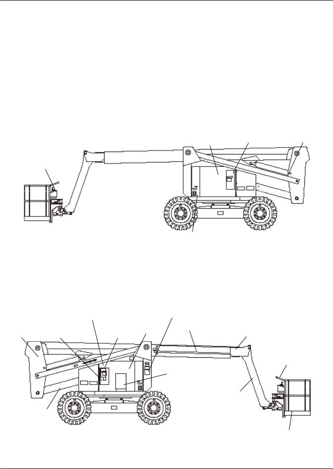
Einleitung
Einleitung
Dieses Handbuch betrifft die Hubarbeitsbühne AB60JRT und muss stets bei der Maschine aufbewahrt werden.
Lesen, verstehen und befolgen Sie alle Sicherheitsregeln und Bedienungsanweisungen, bevor Sie versuchen, die Maschine in Betrieb zu setzen.
Komponentenbezeichnung
Wenn Sie sich wegen Wartungsoder Teileinformationen an UpRight wenden, stellen Sie sicher, dass Sie die MODELLBEZEICHNUNG und die SERIENNUMMERN angeben. Wenn das Typenschild fehlen sollte, finden Sie die SERIENNUMMER auch neben der hinteren Antriebsmotorabdeckung eingeschlagen.
|
Hydrauliköl- |
Not-Ablass- |
Kraftstofftank |
Tank |
ventil |
|
|
Obere Bedienelemente
Not-Ablass- 
ventil
HydraulikölFahrgestell |
Lenkräder |
Filter |
|
Rechte Seite
|
|
Typenschild- |
|
|
Unteres |
Batterie-Trennschalter |
Position |
Schwebende |
|
||
Bedienfeld |
Engine |
Hauptausleger |
|
Wiege |
Controls |
Battery |
Oberer Ausleger |
|
|
|
Plattform |
|
|
|
Bedienungs- |
|
|
|
Handbuch |
|
|
|
Schwenkarm |
Hebebaum
Lenkräder
Plattform-
Fußschalter
Linke Seite
4 |
AB60JRT |
 Loading...