


TL38
POWERED ACCESS
Operator Manual
This rst section of the Operator manual is the English language version.
Betriebsanleitung
Der zweite Abschnitt von dieser Betriebsanleitung ist die Deutsche version.
Guide d’opérateur
La troisième section de ce manuel d'opérateurs est la version de langue Française.
Manual de los Usuario
La cuarta sección de este manual del usuario corresponde a la versión en Español.
Manuale d’uso
Laquinta sezione di questo manuale di operatore è la versione di lingua Italiana.
(EN) Manual part number 500315-005 for serial numbers 1754 to current. (DE) Bestellnummer 500315-005 ab Seriennummer 1754 fortlaufend.
(FR) Manuel Pièce numéro 500315-005 pour numéro série 1754 à présent.
(ES) El número de referencia para el manual es el 500315-005 para la números de serie del 1754 en adelante.
(IT) Manuale Ricambi Numero 500315-005 per Numeri di Serie da 1754 all’attuale.
TL 38
Serial Numbers 1754 – Current
ENGLISH
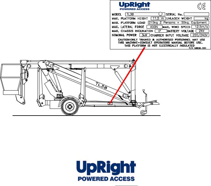
When contacting UpRight for service or parts information, be sure to include the MODEL and SERIAL NUMBERS from the equipment nameplate. Should the nameplate be missing, the SERIAL NUMBER is also stamped on top of the left hand axle
mount.
The Vigo Centre
Washington
Tyne & Wear
NE38 9DA. UK.
www.upright.com

OPERATION MANUAL
WARNING
All personnel shall carefully read, understand and follow all safety rules and operating instructions before operating or performing maintenance on any UpRight aerial work platform.
Safety Rules
Electrocution Hazard |
Tip Over Hazard |
Collision Hazard |
Fall Hazard |
|
|
|
THIS MACHINE IS NOT |
NEVER elevate the platform or drive |
NEVER position the platform |
NEVER climb, stand, or sit on |
INSULATED! |
the machine while elevated unless the |
without first checking for overhead |
platform guardrails or midrail. |
|
machine is on a firm, level surface. |
obstructions or other hazards. |
|
|
|
USE OF THE AERIAL WORK PLATFORM: This aerial work platform is intended to lift persons and his tools as well as the material used for the job. It is designed for repair and assembly jobs and assignments at overhead workplaces (ceilings, cranes, roof structures, buildings etc.). All other uses of the aerial work platform are prohibited!
THIS AERIAL WORK PLATFORM IS NOT INSULATED! For this reason it is imperative to keep a safe distance from live parts of electrical equipment!
Exceeding the specified permissible maximum load is prohibited! See “Special Limitations” on page 4 for details.
The use and operation of the aerial work platform as a lifting tool or a crane (lifting of loads from below upwards or from up high on down) is prohibited!
NEVER exceed the manual force allowed for this machine. See “Special Limitations” on page 4 for details.
DISTRIBUTE all platform loads evenly on the platform.
NEVER operate the machine without first surveying the work area for surface hazards such as holes, drop-offs, bumps, curbs, or debris; and avoiding them.
OPERATE machine only on surfaces capable of supporting stabiliser/outrigger loads.
NEVER operate the machine when wind speeds exceed this machine’s wind rating. See “Beaufort Scale” on page 4 for details.
IN CASE OF EMERGENCY push EMERGENCY STOP switch to deactivate all powered functions.
IF ALARM SOUNDS while platform is elevated, STOP, carefully lower platform and check all outriggers are secure and the chassis is levelbefore resuming operation.
Climbing up the railing of the platform, standing on or stepping from the platform onto buildings, steel or prefab concrete structures, etc., is prohibited!
Dismantling the gravity drop bar or other railing components is prohibited! Always make certain that the gravity drop bar is closed and securely locked!
It is prohibited to keep the gravity drop bar in an open position (held open with tie-straps) when the platform is raised! To extend the height or the range by placing of ladders, scaffolds or similar devices on the platform is prohibited! NEVER perform service on machine while platform is elevated without blocking elevating assembly.
INSPECT the machine thoroughly for cracked welds, loose or missing hardware, hydraulic leaks, loose wire connections, and damaged cables or hoses before using.
VERIFY that all labels are in place and legible before using.
NEVER use a machine that is damaged, not functioning properly, or has damaged or missing labels.
To bypass any safety equipment is prohibited and presents a danger for the persons on the aerial work platform and in its working range.
NEVER charge batteries near sparks or open flame. Charging batteries emit explosive hydrogen gas. Modifications to the aerial work platform are prohibited or permissible only at the approval by UpRight.
AFTER USE, secure the work platform from unauthorized use by turning both keyswitches off and removing key.
Page 1

500315-005
CONTENTS
Introduction . . . . . . . . . . . . . . . . . . . . . . . . . . . . . . . . . . . . . . . . . . . . . . . . . . . . . . . . . . . . . . . . . . . . . . . . . .3
General Description . . . . . . . . . . . . . . . . . . . . . . . . . . . . . . . . . . . . . . . . . . . . . . . . . . . . . . . . . . . . . . . . . . .3
Special Limitations . . . . . . . . . . . . . . . . . . . . . . . . . . . . . . . . . . . . . . . . . . . . . . . . . . . . . . . . . . . . . . . . . . . .4
Platform Capacity . . . . . . . . . . . . . . . . . . . . . . . . . . . . . . . . . . . . . . . . . . . . . . . . . . . . . . . . . . . . . . . . . . . . . . . . . . . 4
Manual Force . . . . . . . . . . . . . . . . . . . . . . . . . . . . . . . . . . . . . . . . . . . . . . . . . . . . . . . . . . . . . . . . . . . . . . . . . . . . . . 4
Beaufort Scale. . . . . . . . . . . . . . . . . . . . . . . . . . . . . . . . . . . . . . . . . . . . . . . . . . . . . . . . . . . . . . . . . . . . . . . . . . . . . . 4
Lift Overload Alarm . . . . . . . . . . . . . . . . . . . . . . . . . . . . . . . . . . . . . . . . . . . . . . . . . . . . . . . . . . . . . . . . . . . . . . . . . . 4
Controls and Indicators . . . . . . . . . . . . . . . . . . . . . . . . . . . . . . . . . . . . . . . . . . . . . . . . . . . . . . . . . . . . . . . .5
Pre-Operation Safety Inspection . . . . . . . . . . . . . . . . . . . . . . . . . . . . . . . . . . . . . . . . . . . . . . . . . . . . . . . . .6
System Function Inspection . . . . . . . . . . . . . . . . . . . . . . . . . . . . . . . . . . . . . . . . . . . . . . . . . . . . . . . . . . . .7
Operation . . . . . . . . . . . . . . . . . . . . . . . . . . . . . . . . . . . . . . . . . . . . . . . . . . . . . . . . . . . . . . . . . . . . . . . . . . . .7
Boom Elevate . . . . . . . . . . . . . . . . . . . . . . . . . . . . . . . . . . . . . . . . . . . . . . . . . . . . . . . . . . . . . . . . . . . . . . . . . . . . . . 7
Boom Lower . . . . . . . . . . . . . . . . . . . . . . . . . . . . . . . . . . . . . . . . . . . . . . . . . . . . . . . . . . . . . . . . . . . . . . . . . . . . . . . 8
Rotate . . . . . . . . . . . . . . . . . . . . . . . . . . . . . . . . . . . . . . . . . . . . . . . . . . . . . . . . . . . . . . . . . . . . . . . . . . . . . . . . . . . . 8
Telescopic Boom. . . . . . . . . . . . . . . . . . . . . . . . . . . . . . . . . . . . . . . . . . . . . . . . . . . . . . . . . . . . . . . . . . . . . . . . . . . . 8
Cage Rotate . . . . . . . . . . . . . . . . . . . . . . . . . . . . . . . . . . . . . . . . . . . . . . . . . . . . . . . . . . . . . . . . . . . . . . . . . . . . . . . 9
Emergency Lowering. . . . . . . . . . . . . . . . . . . . . . . . . . . . . . . . . . . . . . . . . . . . . . . . . . . . . . . . . . . . . . . . . . . . . . . . . 9
Transporting the Work Platform . . . . . . . . . . . . . . . . . . . . . . . . . . . . . . . . . . . . . . . . . . . . . . . . . . . . . . . .10
Hour Meter . . . . . . . . . . . . . . . . . . . . . . . . . . . . . . . . . . . . . . . . . . . . . . . . . . . . . . . . . . . . . . . . . . . . . . . . . .10
Maintenance . . . . . . . . . . . . . . . . . . . . . . . . . . . . . . . . . . . . . . . . . . . . . . . . . . . . . . . . . . . . . . . . . . . . . . . .12
Inspection and Maintenance Schedule. . . . . . . . . . . . . . . . . . . . . . . . . . . . . . . . . . . . . . . . . . . . . . . . . . .13
Daily Preventative Maintenance Checklist . . . . . . . . . . . . . . . . . . . . . . . . . . . . . . . . . . . . . . . . . . . . . . . .13
Labels . . . . . . . . . . . . . . . . . . . . . . . . . . . . . . . . . . . . . . . . . . . . . . . . . . . . . . . . . . . . . . . . . . . . . . . . . . . . .16
Specifications . . . . . . . . . . . . . . . . . . . . . . . . . . . . . . . . . . . . . . . . . . . . . . . . . . . . . . . . . . . . . . . . . . . . . . .17
Page 2 |
TL38 Operator Manual |
Introduction |
500315-005 |
INTRODUCTION
This manual covers operation of the TL50 Work Platforms. This manual must be stored on the machine at all times.
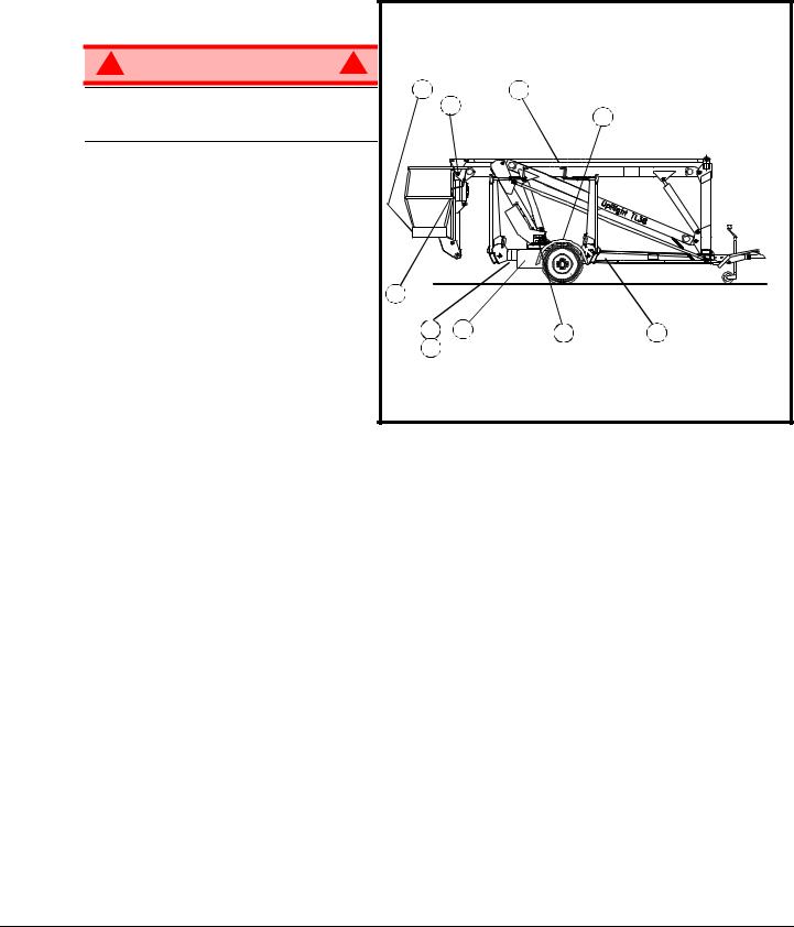
GENERAL DESCRIPTION
1. Platform
! W A R N I N G !
DO NOT use the maintenance platform without guardrails properly assembled and in place
2.Elevating Assembly
3.Chassis
4.Power Module
5.Control Module
6.Platform Controls
7.Manual Case
8.Chassis Controls
9.Hydraulic Fluid Reservoir
10.Batteries
Figure 1: TL 38
1 |
6 |
2 |
|
|
|
9 |
|
|
|
|
|
7 |
|
|
|
4 |
5 |
8 |
3 |
10 |
|
|
|
TL38 Operator Manual |
Page 3 |

500315-005 |
Special Limitations |
SPECIAL LIMITATIONS
Elevating the Work Platform is limited to firm, level surfaces only.
!D A N G E R !
The elevating function shall ONLY be used when the work platform is level and on a firm surface.
PLATFORM CAPACITY
The maximum capacity for the MACHINE, including occupants is determined by model and options, and is listed in “Specifications” on page 15.
!D A N G E R !
DO NOT exceed the maximum platform capacity or the platform occupancy limits for this machine.
MANUAL F ORCE
Manual force is the force applied by the occupants to objects such as walls or other structures outside the work platform.
The maximum allowable manual force is limited to 200 N (45 lbs.) of force per occupant, with a maximum of 400 N (90 lbs.) for two or more occupants.
!D A N G E R !
DO NOT exceed the maximum amount of manual force for this machine.
BEAUFORT SCALE
Never operate the machine when wind speeds exceed 25 km/h (15 mph) [Beaufort scale 4].
BEAUFORT |
|
WIND SPEED |
|
GROUND CONDITIONS |
||
RATING |
m/s |
km/h |
ft/s |
mph |
||
|
||||||
3 |
3,4~5,4 |
12,25~19,4 |
11.5~17.75 |
7.5~12.0 |
Papers and thin branches move, flags wave. |
|
4 |
5,4~8,0 |
19,4~28,8 |
17.75~26.25 |
12.0~18 |
Dust is raised, paper whirls up, and small branches sway. |
|
5 |
8,0~10,8 |
28,8~38,9 |
26.25~35.5 |
18~24.25 |
Shrubs with leaves start swaying. Wave crests are apparent in ponds or swamps. |
|
6 |
10,8~13,9 |
38,9~50,0 |
35.5~45.5 |
24.5~31 |
Tree branches move. Power lines whistle. It is difficult to open an umbrella. |
|
7 |
13,9~17,2 |
50,0~61,9 |
45.5~56.5 |
31.~38.5 |
Whole trees sway. It is difficult to walk against the wind. |
|
LIFT OVERLOAD ALARM
The TL38 is fitted with a load sensing system designed to comply with the requirements os BS EN 280 : 2001
If a load equivelent to 90% of safe working load is lifted a fault code “03” will be displayed on the digital display on the platform control box. If a load which is greater than the safe working load is present in the basket all machine functions will cease to operate and an acoustic warning will sound. In order to return to normal operation a load equal to or less than the safe working load must be present in the basket and the power must be re-cycled, power can be re-cycled by pushing the emergency stop button and releasing it again.
!D A N G E R !
Never operate the machine with a platform load greater than the rated capacity.
Page 4 |
TL38 Operator Manual |
Controls and Indicators |
500315-005 |
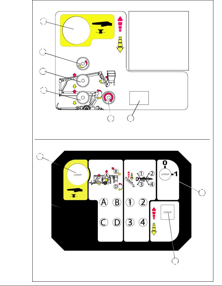
CONTROLS AND INDICATORS
Figure 2: Controls and Indicators
1
2
3

4
1.Emergency stop |
6.Display |
2.Telescope |
7.Joystick |
3.Upper Boom |
|
4.Lower Boom |
|
5.Rotate |
|
Platform Controls
7
5 |
6 |
Chassis Controls
1
 5
5 
1.Emergency stop |
5.Key Switch |
2.Machine Controls |
|
3.Outrigger Controls |
|
4.Analog Rocker |
|
{ { |
|
2 |
3 |
4
TL38 Operator Manual |
Page 5 |

500315-005 |
Pre-Operation Safety Inspection |
PRE-OPERATION SAFETY INSPECTION |
|
NOTE: Carefully read, understand and follow all safety rules, operating instructions, labels and National Safety Instructions/Requirements. Perform the following steps each day before use.
1.Open module and inspect for damage, fluid leaks or missing parts.
2.Check the level of the hydraulic fluid with the platform fully lowered. The hydraulic reservoir is located in the Control Module. The fluid level must be between the MIN and MAX lines. Add hydraulic fluid if necessary.
3.Check that fluid level in the batteries is correct.
4.Verify that batteries are charged.
5.Check that A.C. extension cord has been disconnected from the charger plug.
6.Check that all guardrails are in place and all fasteners are properly tightened.
7.Inspect the machine thoroughly for cracked welds and structural damage, loose or missing hardware, hydraulic leaks, damaged control cable, loose wire connections and wheel bolts.
Page 6 |
TL38 Operator Manual |
System Function Inspection |
500315-005 |
SYSTEM FUNCTION INSPECTION
Refer to Figure 2 for the locations of various controls and indicators.
! W A R N I N G !
STAND CLEAR of the work platform while performing the following checks.
Before operating the work platform, survey the work area for surface hazards such as holes, drop-offs, bumps and debris.
Check in ALL directions, including above the work platform, for obstructions and electrical conductors.
1.Move the machine, if necessary, to an unobstructed area to allow for full elevation.
2.Pull Chassis Emergency Stop Switch to the ON position.
3.Pull Platform Emergency Stop Switch to the ON position.
4.Deploy the Outriggers, this is done from the lower control panel, an audible warning will sound until the outriggers are fully deployed and the machine is level, ensure that all four individual outrigger lights are illuminated. Fine tuning of the chassis inclination can be achieved by holding each individual outrigger button and using the analog rocker. (ref: chassis controls illustration on page 5)
5.Visually inspect the elevating assembly, lift cylinder, cables, and hoses for cracked welds and structural damage, loose hardware, hydraulic leaks, loose wire connections, and erratic operation. Check for missing or loose parts.
6.Test each machine function (Lift, Slew, Jib) from the lower control station by pressing and holding the desired function button then moving the Analog Rocker to the Up or Down position (ref: chassis controls illustration on page 5)
7.Open the Emergency Lowering Valve (see Figure 3) by pulling the knob out to check for proper operation. When the platform is lowered, release the knob.
8.Push the Chassis Emergency Stop Switch to check for proper operation. All machine functions should be disabled. Twist the Chassis Emergency Stop Switch to resume.
9.Climb onto the cage.
10.Check that the route is clear of obstacles (persons, obstructions, debris), is level, and is capable of supporting the outrigger loads.
11.Mount the platform and properly close the drop bar.
12.Test each machine function (Lift, Slew, Jib) from the upper control station by pressing the desired function button then moving the Joystick to the Forward or Back position (ref: platform controls illustration on page 5)
13.Push the Platform Emergency Stop Switch to check for proper operation. All machine functions should be disabled. Pull out the Platform Emergency Stop Switch to resume.
OPERATION
Before operating the work platform, ensure that the Pre-Operation Safety Inspection has been completed and that any deficiencies have been corrected. Never operate a damaged or malfunctioning machine.
The operator must be thoroughly trained on this machine.
ELEVATING THE PLATFORM
1.Ensure the outriggers are deployed and the machine is level.
2.Select either the lower or upper boom lift function button (the button will illuminate to confirm selection).
3.While engaging the Interlock Switch, push the Control Handle forward.
4.If the machine is not level the tilt alarm will sound and the machine will not lift.
TL38 Operator Manual |
Page 7 |
500315-005 |
Operation |
LOWERING THE PLATFORM
1.Ensure the outriggers are deployed and the machine is level.
2.Select either the lower or upper boom lift function button (the button will illuminate to confirm selection).
3.While engaging the Interlock Switch, pull the Control Handle backwards.
4.If the machine is not level the tilt alarm will sound and the machine will not descend.
ROTATING THE PLATFORM
1.Ensure the outriggers are deployed and the machine is level.
2.Select the rotate function button (the button will illuminate to confirm selection).
3.While engaging the Interlock Switch, move the Control Handle forwards or backwards to achieve clockwise or counterclockwise rotation.
4.If the machine is not level the tilt alarm will sound and the machine will not rotate.
OPERATING THE JIB
1.Ensure the outriggers are deployed and the machine is level.
2.Select jib function button (the button will illuminate to confirm selection).
3.While engaging the Interlock Switch, move the Control Handle forwards or backwards to jib out or jib in.
4.If the machine is not level the tilt alarm will sound and the machine will not telescope.
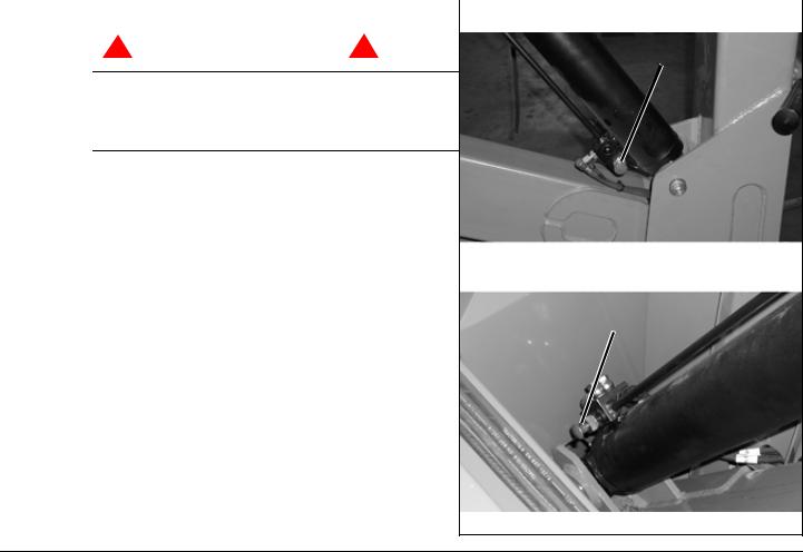
EMERGENCY LOWERING
|
|
Figure 3: Emergency Lowering Valve |
||
|
|
Upper Boom |
||
|
|
|
|
|
! W A R N I N G ! |
|
|
|
|
|
|
Emergency Lowering Knob |
|
|
|
|
|
|
|
If the platform should fail to lower, NEVER climb down the elevating assembly.
Stand clear of the elevating assembly while operating the Emergency Lowering Valve Knob.
TL38
The Emergency Lowering Valve for the TL38 is located on the valve block of each lift cylinder.
1. |
Open the Emergency Lowering Valve by pushing |
|
|
|
|
and holding the knob. |
Lower Boom |
||
2. |
To close, release the knob. The platform will not |
|||
|
|
|||
|
elevate if the Emergency Lowering Valve is |
|
|
|
|
open. |
|
Emergency Lowering Knob |
|
|
|
|
|
|
Page 8 |
TL38 Operator Manual |
Transportation |
500315-005 |
TRANSPORTATION
C A U T I O N
The TL38 is not designed to be forklifted, and does not have provision on the Chassis to allow this method of lifting. Ui recommends the procedure below for handling the machine.
! W A R N I N G !
See specifications at rear of manual for the weight of the work platform and be certain that lifting apparatus is of adequate capacity to lift the platform.
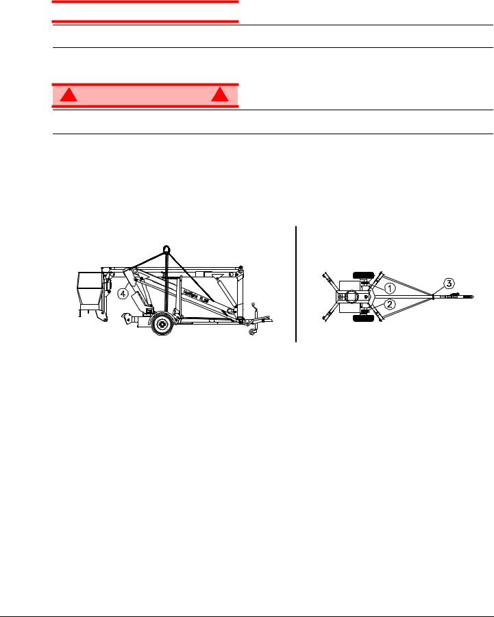
BY CRANE
The TL38 may be lifted by an overhead hoist crane in the following manner:
Two lifting straps capable of safely supporting the total weight of the TL38 (1468Kg (3,237lbs)), and at least 220cm long are required. This minimum length is important to ensure the correct lifting angle. The straps should be positioned as shown in.
The two lifting straps (Positions 1 & 2) should be positioned either side of the TL38’s axle assembly at the points indicated. Care must be taken to ensure the straps do not interfere with any of the other part of the TL38.
Two securing lines (Positions 3 & 4) should also be used when lifting the TL38 Work Platform. These are used to maintain the balance of the TL38 but are NOT to be considered as lifting points. Position 3 shows the securing line around the Tow Bar where the Cycle Guard Frames meet. Position 4 shows the securing line around the First Post. This line should be secured below the Boom Rest, however care should be taken not to damage the Boom Rest Limit Switch or its cable on a TL38 with hydraulic outriggers.
BY ROAD
It is important that before commencing transport to ensure the vehicle used is capable of towing 2000kg.
The TL38 is a road approved vehicle and therefore may be transported behind a motor vehicle of suitable towing capacity. It is recommended that the vehicle used should have a tow bar where the top of the ball is at a height of between 1.42 ft (435 mm) and 1.64 ft (500 mm) above surface level. These dimensions are important for the following reasons;
1.The bottom of the Platform may be in danger of hitting the surface while driving if the tow hitch is above the upper limit.
2.The towing vehicle will support too much weight if the Towhitch is too low.
TL38 Operator Manual |
Page 9 |

500315-005 |
Transportation |
Care should always be taken while towing the TL38 on an uneven or sloped surface. It is recommended that the set of procedures that follow should be incorporated into a normal working practice for towing the TL38 Work Platform. The Procedures which should be followed when transporting the TL38 are
1.The Platform is to be fully lowered, retracted and slewed in the correct position.
2.The Platform is to be securely stowed by closing the boom lockdown.
3.The Jockey Wheel that is fitted to the Towhitch is to be extended until the Receiver is close to the height of the vehicle’s tow bar.
4.The Hand Brake is pulled to engage the brakes (important if the machine is not on a level surface).
5.The Outriggers are to be fully retracted and secured in position.
6.The key is turned to the off position.
7.Move the vehicle as close as possible to the Receiver.
8.Lift the Towhitch on to the tow bar and make sure the Receiver is properly secured.
9.Release the Hand Brake and retract the Jockey Wheel.
It is important that the Jockey Wheel is retracted as fully as possible so that the wheel will not slew (turn) while being transported. Failure to do so could result in damage to the Jockey Wheel.
10.The tailboard harness is connected to the vehicle’s braking system by means of a 7 Pin Plug.
11.Attach the Breakaway Safety Cable to the towing vehicle.
The TL38 may then be towed.
If the TL38 is to be transported by other means then it must be securely tied down to the transporting unit at several points.
Recommended securing points are the four outrigger support members on the Chassis and the Tow Barweldment. Further securing points should be used if the terrain on which the unit is travelling is rough or uneven. Care should be taken when using tie downs that sensitive parts of the TL38 (i.e. hosing, cabling etc.) are not affected.
ALWAYS ensure that the Hand Brake is fully applied, that all the booms are FULLY stowed and that the Boom Lock Down Pin is in place.
HOUR METER
To access the hour meter function perform the following steps.
1.Climb into the basket (with the machine powered up)
2.Push the platform emergency stop button.
3.Hold down the following buttons, Jib and Upper Boom Lift.
4.While holding the buttons twist the emergency stop button to return power to the machine.
5.“hr” will now be displayed on the readout, Pressing the right turn button will scroll through the accumulated hours two digits at a time. For example, if pressing the right turn button once displays “20”, pressing it a 2nd time displays “58”, and pressing it a 3rd time displays “hr”, the elapsed time of operation is 2058 hours.
Page 10 |
TL38 Operator Manual |
Transportation |
500315-005 |
|||
|
BATTER Y MAINTENANCE |
|||
|
|
|
|
|
|
! W A R N I N G |
! |
|
|
|
|
|
|
|
Hazard of explosive gas mixture. Keep sparks, flame, and smoking material away from batteries. Always wear safety glasses when working near batteries.
Battery fluid is highly corrosive. Thoroughly rinse away any spilled fluid with clean water.
Always replace batteries with Ui batteries or manufacturer approved replacements weighing 26,3 kg (58 lbs.) each.
•Check the battery fluid level daily, especially if the work platform is being used in a warm, dry climate.
•If electrolyte level is lower than 10 mm (3/8 in.) above the plates add distilled water only. DO NOT use tap water with high mineral content, as it will shorten battery life.
•Keep the terminals and tops of the batteries clean.
•Refer to the Service Manual to extend battery life and for complete service instructions.
BATTERY CHARGING
Figure 4:
Charge the batteries at the end of each work shift or sooner if the batteries have been discharged.
! W A R N I N G !
Charge the batteries in a well ventilated area.
Do not charge the batteries when the work platform is near a source of sparks or flames.
Permanent damage to the batteries will result if the batteries are not immediately recharged after discharging.
Never leave the battery charger operating for more than two days.
Never disconnect the cables from the batteries when the charger is operating.
Keep the charger dry.
1.Check the battery fluid level. If the battery fluid level is lower than 10 mm (3/8 in.) above the plates add distilled water only.
2.Connect an appropriate extension cord to charger outlet plug in Left Module Door. Plug the extension cord into a properly grounded outlet of proper voltage and frequency.
3.The charger turns on automatically after a short delay. The LED charge indicator will illuminate. After completion of the charge cycle the LED will blink, indicating that the charger is in a continuing maintenance mode. DO NOT leave the charger plugged in for more than 48 hours, as permanent damage to the batteries may occur.
NOTE: The battery charger circuit must be used with a GFI (Ground Fault Interrupt) outlet.
NOTE: DO NOT operate the machine while the charger is plugged in.
TL38 Operator Manual |
Page 11 |

500315-005 |
Inspection and Maintenance Schedule |
INSPECTION AND MAINTENANCE SCHEDULE |
|
The Complete Inspection consists of periodic visual and operational checks, along with periodic minor adjustments that assure proper performance. Daily inspection will prevent abnormal wear and prolong the life of all systems. The inspection and maintenance schedule should be performed at the specified intervals. Inspection and maintenance shall be performed by personnel who are trained and familiar with mechanical and electrical procedures.
! W A R N I N G !
Before performing preventative maintenance, familiarize yourself with the operation of the machine.
Always block the elevating assembly whenever it is necessary to perform maintenance while the platform is elevated.
The daily preventative maintenance checklist has been designed for machine service and maintenance. Please photocopy this page and use the checklist when inspecting the machine.
DAILY PREVENTATIVE MAINTENANCE CHECKLIST
MAINTENANCE TABLE KEY
Y = Yes/Acceptable
N = No/Not Acceptable
R = Repaired/Acceptable
COMPONENT |
INSPECTION OR SERVICES |
Y |
N |
R |
|
|
|
|
|
Battery |
Check electrolyte level. |
|
|
|
|
|
|
|
|
Check battery cable condition. |
|
|
|
|
|
|
|
|
|
|
|
|
|
|
Chassis |
Check hoses for pinch or rubbing points. |
|
|
|
|
|
|
|
|
Check welds for cracks. |
|
|
|
|
|
|
|
|
|
|
|
|
|
|
Control Cable |
Check the exterior of the cable for pinching, |
|
|
|
binding or wear. |
|
|
|
|
|
|
|
|
|
|
|
|
|
|
Controller |
Check switch operation. |
|
|
|
|
|
|
|
|
Drive Motors |
Check for operation and leaks. |
|
|
|
|
|
|
|
|
Elevating |
Inspect for structural cracks. |
|
|
|
Assembly |
|
|
|
|
|
|
|
|
|
|
|
|
|
|
Emergency |
Operate the emergency lowering valve and check |
|
|
|
Lowering System |
for serviceability. |
|
|
|
|
|
|
|
|
Entire Unit |
Check for and repair collision damage. |
|
|
|
PREVENTATIVE MAINTENANCE REPORT
Date:_______________________________________
Owner: _____________________________________
Model No:___________________________________
Serial No: ___________________________________
Serviced By: _________________________________
COMPONENT |
INSPECTION OR SERVICES |
Y |
N |
R |
|
|
|
|
|
|
|
Hydraulic Fluid |
Check fluid level. |
|
|
|
|
|
|
|
|
|
|
Hydraulic Pump |
Check for hose fitting leaks. |
|
|
|
|
|
|
|
|
|
|
Hydraulic System |
Check for leaks. |
|
|
|
|
|
|
|
|
|
|
Labels |
Check for peeling, missing, or unreadable labels |
|
|
|
|
& replace. |
|
|
|
||
|
|
|
|
||
|
|
|
|
|
|
Platform Deck |
Check welds for cracks. |
|
|
|
|
and Rails |
|
|
|
||
|
|
|
|
||
|
|
|
|
|
|
Platform Deck |
Check condition of deck. |
|
|
|
|
and Rails |
|
|
|
||
|
|
|
|
||
|
|
|
|
|
|
Tires and Wheels |
Check for damage. |
|
|
|
|
|
|
|
|
|
Page 12 |
TL38 Operator Manual |

Labels |
500315-005 |
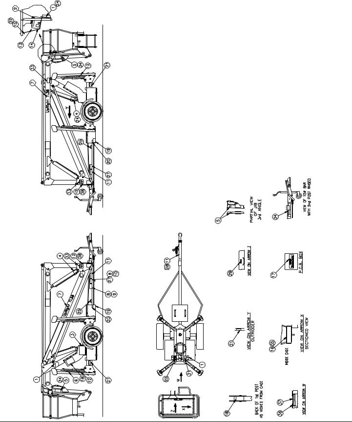
LABELS
These labels shall be present and in good condition before operating the work platform. Be sure to read, understand and follow these labels when operating the work platform.
ITEM |
PART NO. |
DESCRIPTION |
QTY. |
1 |
057421-000 |
DECAL - ELECTROCUTION HAZARD |
2 |
2 |
057420-000 |
DECAL - TIP OVER HAZARD |
1 |
3 |
058608-001 |
DECAL - LOWER CONTROL BOX |
1 |
4 |
057382-000 |
DECAL - EMERGENCY LOWERING |
2 |
5 |
058860-000 |
DECAL - HAND HAZARD |
3 |
6 |
057385-000 |
HAZARD TAPE (900mm LONG) |
8 |
7 |
058609-000 |
DECAL - "Ui" LOGO |
2 |
8 |
057339-001 |
PLASTIC PUSH RIVET |
2 |
9 |
058838-000 |
E.U. NAME PLATE |
1 |
10 |
058836-000 |
V.I.N. PLATE |
1 |
11 |
057416-000 |
DECAL - BEFORE TOWING |
1 |
12 |
057418-000 |
DECAL - LOCK OUTRIGGER TOWING |
2 |
13 |
058607-000 |
DECAL - UPPER CONTROL BOX |
1 |
14 |
058186-000 |
DECAL - ON/OFF UPPER CONTROL |
1 |
15 |
058016-000 |
DECAL - MACHINE GENERAL INSTR. |
1 |
16 |
057392-000 |
DECAL - S.W.L. LARGE CE |
1 |
17 |
057387-000 |
DECAL - UPPER QUADRAPOWER |
1 |
19 |
057430-000 |
DECAL - EXPLOSION HAZARD |
2 |
20 |
057429-000 |
DECAL - BATTERY FLUID LEVEL |
2 |
21 |
057417-000 |
DECAL - TIP OVER HAZARD |
4 |
22 |
057507-010 |
DECAL - ARROW |
2 |
23 |
058992-000 |
DECAL - BOOM LOCK PIN |
1 |
TL38 Operator Manual |
Page 13 |
500315-005 |
Labels |
LABELS
These labels shall be present and in good condition before operating the work platform. Be sure to read, understand and follow these labels when operating the work platform.
ITEM |
PART NO. |
DESCRIPTION |
1 |
057421-000 |
DECAL - ELECTROCUTION HAZARD |
2 |
057420-000 |
DECAL - TIP OVER HAZARD |
3 |
058608-000 |
DECAL - LOWER CONTROL BOX |
4 |
057382-000 |
DECAL - EMERGENCY LOWERING |
5 |
058860-000 |
DECAL - HAND HAZARD |
6 |
057385-000 |
HAZARD TAPE (900mm LONG) |
7 |
058609-000 |
DECAL - "Ui" LOGO |
8 |
057339-001 |
PLASTIC PUSH RIVET |
9 |
058838-000 |
E.U. NAME PLATE |
10 |
058836-000 |
V.I.N. PLATE |
11 |
057416-000 |
DECAL - BEFORE TOWING |
12 |
057418-000 |
DECAL - LOCK OUTRIGGER TOWING |
13 |
058607-000 |
DECAL - UPPER CONTROL BOX |
14 |
058186-000 |
DECAL - ON/OFF UPPER CONTROL |
15 |
058016-000 |
DECAL - MACHINE GENERAL INSTR. |
16 |
057392-000 |
DECAL - S.W.L. LARGE CE |
17 |
057387-000 |
DECAL - UPPER QUADRAPOWER |
18 |
- |
- |
19 |
057430-000 |
DECAL - EXPLOSION HAZARD |
20 |
057429-000 |
DECAL - BATTERY FLUID LEVEL |
21 |
057417-000 |
DECAL - TIP OVER HAZARD |
22 |
057507-010 |
DECAL - ARROW |
23 |
058992-000 |
DECAL - BOOM LOCK PIN |
Page 14 |
TL38 Operator Manual |

|
Specifications |
|
|
|
500315-005 |
||
SPECIFICATIONS |
|
|
|
|
|
||
|
|
|
|
|
|
||
|
|
ITEM |
MANUAL OUTRIGGERS |
HYDRAULIC OUTRIGGERS |
|
||
|
|
Duty Cycle |
30% of 8 hour cycle |
30% of 8 hour cycle |
|
||
|
|
Platform Size |
0.7m x 1.3m[2.3ft x 4.3ft] (inside guardrails) |
0.7m x 1.3m [2.3ft x 4.3ft] (inside guardrails) |
|
||
|
|
Max. Platform Capacity |
215kg [473lbs] |
215kg [473lbs] |
|
||
|
|
Max. # of Occupants |
2 People |
2 People |
|
||
|
|
Height |
|
|
|
|
|
|
|
Maximum Working Height |
13.45m [44.1ft] |
13.49m |
[44.3ft] |
|
|
|
|
Maximum Platform Height |
11.45m [38ft] |
11.49m |
[38ft] |
|
|
|
|
Min. Platform Height |
0.65m [2.1ft] |
0.65m |
[2.1ft] |
|
|
|
|
Max. Working Outreach |
6m [19.7ft] |
6m [19.7ft] |
|
||
|
|
Travelling Dimensions: |
|
|
|
|
|
|
|
Length |
6.08m |
[19.9ft] |
6.08m |
[19.9ft] |
|
|
|
Width |
1.53m |
[5.0ft] |
1.53m |
[5.0ft] |
|
|
|
Height |
2.00m |
[6.6ft] |
2.00m |
[6.6ft] |
|
|
|
Outrigger Spread |
(front-rear x side-side) |
(front-rear x side-side) |
|
||
|
|
Max. Clearance |
3.40m x 3.42m |
[11.2ft x 11.2ft] |
3.39m x 3.45m [11.1ft x 11.3ft] * |
|
|
|
|
|
|
|
3.46m x 3.56m [11.4ft x 11.7ft]** |
|
|
|
|
Min. Effective Clearance |
3.25m x 3.27m [10.7ft x 10.7ft] |
3.16m x 3.22m [10.4ft x 10.6ft]* |
|
||
|
|
|
|
|
3.24m x 3.33m [10.6ft x 10.9ft]** |
|
|
|
|
Rotation |
370 degrees non-continuous |
370 degrees non-continuous |
|
||
|
|
Gross Weight |
1468kg [3,237lbs] |
1468kg [3,237lbs] |
|
||
|
|
Maximum Towable Speed |
83km/h [50mph]*** |
83km/h [50mph]*** |
|
||
|
|
Power Source |
24V DC 4HP, 4 X 6V 220Ah Batteries |
24V DC 4HP, 4 X 6V 220Ah Batteries |
|
||
|
|
System Voltage |
24V DC |
24V DC |
|
||
|
|
Battery Charger |
24V 25A 220/110VAC 50/60 Hz |
24V 25A 220/110VAC 50/60 Hz |
|
||
|
|
Hydraulic TankCapacity |
15 Litres [3.9 Gallons US] |
15 Litres [3.9 Gallons US] |
|
||
|
|
Max. Hydraulic Pressure |
155 Bar [2,250psi] |
155 Bar [2,250psi] |
|
||
|
|
Hydraulic Oil |
ISO #46 |
ISO #46 |
|
||
|
|
Lift System |
2 Double Acting Lift Cylinders With |
2 Double Acting Lift Cylinders With |
|
||
|
|
|
Lock Valves And Manual |
Lock Valves And Manual |
|
||
|
|
|
Emergency Lowering Facility. |
Emergency Lowering Facility. |
|
||
|
|
|
1 Double Acting Lift (Jib) Cylinder |
1 Double Acting Lift (Jib) Cylinder |
|
||
|
|
Control System |
One handed Proportional Joystick |
One handed Proportional Joystick |
|
||
|
|
|
Operating Energy Efficient Motor |
Operating Energy Efficient Motor |
|
||
|
|
|
Control System. |
Control System. |
|
||
|
|
Tyres |
185 R13 6PLY |
185 R13 6PLY |
|
||
|
|
Brake System |
Automatic Reverse & Overrun Brakes |
Automatic Reverse & Overrun Brakes |
|
||
|
|
|
Handbrake |
Handbrake |
|
||
|
|
Maximum Continuous Sound |
|
|
|
|
|
|
|
Pressure Level At Operation |
|
|
|
|
|
|
|
Stations |
74.6 dB(A) |
74.6 dB(A |
|
||
*Outriggers Deployed at full height = Minimum footprint
**Outriggers Deployed at min. height = Maximum footprint
***Subject to local regulations
*Specifications are subject to change without notice. Hot weather or heavy use may affect performance. Refer to the Service Manual for complete parts and service information.
This machine meets or exceeds all applicable CE and GS machinery directive requirements.
TL38 Operator Manual |
Page 15 |
TL 38
Seriennummern 1754 – aktuell
DEUTSCH
Stellen Sie sicher, dass Sie die MODELLund SERIENNUMMERN auf dem Gerätetypenschild angeben, wenn Sie sich mit UpRight bezüglich Wartungsoder Ersatzteilinformationen in Verbindung setzen. Sollte das Typenschild fehlen, finden Sie die SERIENNUMMER auch auf dem Fahrwerk über der vorderen Schwenkachse.
The Vigo Centre
Washington
Tyne & Wear
NE38 9DA. UK.
www.upright.com

BETRIEBSANLEITUNG
WARNUNG
Alle Bediener müssen die Sicherheitsregeln und Betriebsanleitungen gründlich durchlesen, verstehen und befolgen, bevor sie an irgendeiner Ui-Hocharbeitsbühne Wartungsarbeiten ausführen oder die Arbeitsbühne in Betrieb nehmen .
Sicherheitsregeln
Elektroschockgefahr |
Kippgefahr |
Kollisionsgefahr |
Sturzgefahr |
|
|
|
DIESE MASCHINE IST NICHT |
NIEMALS die Plattform ausfahren |
Plattform NIEMALS in Position |
NIEMALS auf das obere oder |
ISOLIERT! |
oder die Maschine mit ausgefahrener |
bringen, ohne vorher sicherzustellen, |
mittlere Gestänge des |
|
Plattform fortbewegen, wenn sich die |
dass der Bereich über der Plattform |
Plattformgeländers klettern |
|
|||
|
Maschine nicht auf einer festen, |
frei von Hindernissen und anderen |
und auch nicht darauf stehen |
|
ebenen Fläche befindet. |
Gefahren ist. |
oder sitzen. |
EINSATZ DER HOCHARBEITSBÜHNE : Diese Hocharbeitsbühne dient dazu, Personen und Werkzeuge sowie die für die jeweilige Arbeit erforderlichen Materialien zu transportieren. Sie wurde speziell für Reparaturund Montagearbeiten sowie für Einsatzbereiche k onzipiert, die sich oberhalb der Mitarbeiter befinden, sodass die Mitarbeiter nach oben gerichtet arbeiten müssen (z. B. Decken, Kräne, Dachst rukturen, Gebäude etc.). Jede andere Verwendung der Hocharbeitsbühne ist strikt verboten!
DIESE HOCHARBEITSBÜHNE IST NICHT ISOLIERT! Aus diesem Grund muss zwingend ein Sicherheitsabstand zu allen leitfähigen Teilen der elektrischen Ausrüstung eingehalten werden!
Die angegebene zulässige Höchstlast darf nicht überschritten werden!Nähere Informationen hierzu finden Sie im Abschnitt “Beschränkungen” auf Seite 4.
Es ist strikt verboten, die Hocharbeitsbühne als Hubwerkzeug oder Kran einzusetzen (d. h. um Lasten von unten nach oben oder von oben nach unten zu befördern).
Die für diese Maschine zulässige manuelle Kraft NIEMALS überschreiten.Nähere Informationen hierzu finden Sie im Abschnitt “Beschränkungen” auf Seite 4.
Lasten immer gleichmäßig auf der Plattform VERTEILEN.
Vor Inbetriebnahme der Maschine IMMER ZUERST die Aufstellfläche im Arbeitsbereich auf Gefahren wie Bodenlöcher, ausgelaufene Flüssigkeiten, Bodenerhebungen, Kanten oder Schutt untersuchen und diese umgehen bzw. beseitigen.
Maschine nur auf Oberflächen IN BETRIEB NEHMEN, die die Last der Abstützausleger tragen können.
Maschine NIEMALS in Betrieb nehmen, wenn die tatsächliche Windgeschwindigkeit höher ist als die Windgeschwindigkeit, für die die Maschine ausgelegt ist. Nähere Informationen hierzu finden Sie im Abschnitt “Beaufort-Skala” auf Seite 4.
IM NOTFALL NOT-AUS-Schalter drücken, um alle strombetriebenen Funktionen zu deaktivieren.
WENN EIN ALARM ERTÖNT , während die Plattform ausgefahren wird, Plattform ANHALTEN, vorsichtig einfahren (absenken) und überprüfen, ob alle Abstützausleger sicher stehen und das Fahrwerk nivelliert ist, bevor Sie den Betrieb wieder aufnehmen.
Auf das Schutzgeländer der Plattform zu klettern, auf Gebäuden, Stahloder vorgefertigten Betonstrukturen zu stehen oder von d er Plattform aus darauf zu klettern etc. ist verboten!
Die Schutzschranke oder andere Komponenten des Schutzgeländers zu demontieren ist verboten! Vergewissern Sie sich immer, dass die Schutzschranke geschlossen und sicher verriegelt ist!
Es ist verboten, die Schutzschranke geöffnet zu halten (z. B. mit Befestigungsgurten), wenn die Arbeitsplattform ausgefahren wird!
Die Höhe oder Reichweite der Plattform durch Anbringen von Leitern, Gerüsten oder ähnlichen Vorrichtungen zu vergrößern ist verboten!
IMMER ZUERST die Hubvorrichtung blockieren, bevor bei ausgefahrener Plattform Wartungsoder Instandhaltungsarbeiten an der Maschine durchgeführt werden.
Maschine vor jedem Gebrauch sorgfältig auf Risse an Schweißstellen, lose oder fehlende Beschläge, Leckagen in der Hydraulikvorr ichtung, gelöste Kabelverbindungen und beschädigte Kabel oder Schläuche UNTERSUCHEN.
Vor Gebrauch SICHERSTELLEN, dass alle Bezeichnungsschilder ordnungsgemäß angebracht und vollständig lesbar sind.
NIEMALS eine Maschine benutzen, die beschädigt ist, nicht ordnungsgemäß funktioniert oder deren Bezeichnungsschilder Beschädigungen aufweisen oder sogar ganz fehlen.
Sicherheitseinrichtungen zu umgehen ist verboten und stellt eine Gefahr für alle Personen dar, die sich auf der Hocharbeitsbühne und in deren Arbeitsbereich befinden.
Batterien NIEMALS in der Nähe von Funkenquellen oder offenen Flammen aufladen. Beim Aufladen von Batterien wird explosives Wasserstoffgas freigesetzt.
Änderungen an der Hocharbeitsbühne sind verboten bzw. nur mit ausdrücklicher Genehmigung von Ui zulässig.
NACH GEBRAUCH ist die Hocharbeitsbühne gegen unbefugten Gebrauch durch Dritte zu sichern. Hierzu müssen beide Schlüsselschalter auf “Aus” gestellt und die Schlüssel abgezogen werden.
Seite 1

500315-005
INHALT
Einführung. . . . . . . . . . . . . . . . . . . . . . . . . . . . . . . . . . . . . . . . . . . . . . . . . . . . . . . . . . . . . . . . . . . . . . . . . . .3 Allgemeine Beschreibung . . . . . . . . . . . . . . . . . . . . . . . . . . . . . . . . . . . . . . . . . . . . . . . . . . . . . . . . . . . . . .3
Beschränkungen . . . . . . . . . . . . . . . . . . . . . . . . . . . . . . . . . . . . . . . . . . . . . . . . . . . . . . . . . . . . . . . . . . . . .4
Tragfähigkeit der Plattform . . . . . . . . . . . . . . . . . . . . . . . . . . . . . . . . . . . . . . . . . . . . . . . . . . . . . . . . . . . . . . . . . . . . . 4 Manuelle Kraft . . . . . . . . . . . . . . . . . . . . . . . . . . . . . . . . . . . . . . . . . . . . . . . . . . . . . . . . . . . . . . . . . . . . . . . . . . . . . . 4 Beaufort-Skala . . . . . . . . . . . . . . . . . . . . . . . . . . . . . . . . . . . . . . . . . . . . . . . . . . . . . . . . . . . . . . . . . . . . . . . . . . . . . . 4 Überlastalarm . . . . . . . . . . . . . . . . . . . . . . . . . . . . . . . . . . . . . . . . . . . . . . . . . . . . . . . . . . . . . . . . . . . . . . . . . . . . . . . 4
Bedienelemente und Anzeigen . . . . . . . . . . . . . . . . . . . . . . . . . . . . . . . . . . . . . . . . . . . . . . . . . . . . . . . . . .5 Sicherheitsprüfung vor Inbetriebnahme . . . . . . . . . . . . . . . . . . . . . . . . . . . . . . . . . . . . . . . . . . . . . . . . . .6 Überprüfung der Systemfunktionen . . . . . . . . . . . . . . . . . . . . . . . . . . . . . . . . . . . . . . . . . . . . . . . . . . . . .7
Bedienung . . . . . . . . . . . . . . . . . . . . . . . . . . . . . . . . . . . . . . . . . . . . . . . . . . . . . . . . . . . . . . . . . . . . . . . . . . .7
Ausfahren der Plattform . . . . . . . . . . . . . . . . . . . . . . . . . . . . . . . . . . . . . . . . . . . . . . . . . . . . . . . . . . . . . . . . . . . . . . . 7 Einfahren der Plattform . . . . . . . . . . . . . . . . . . . . . . . . . . . . . . . . . . . . . . . . . . . . . . . . . . . . . . . . . . . . . . . . . . . . . . . . 8 Drehen der Plattform . . . . . . . . . . . . . . . . . . . . . . . . . . . . . . . . . . . . . . . . . . . . . . . . . . . . . . . . . . . . . . . . . . . . . . . . . . 8 Bedienung des kurzen Gelenkauslegers. . . . . . . . . . . . . . . . . . . . . . . . . . . . . . . . . . . . . . . . . . . . . . . . . . . . . . . . . . . 8 Notfallabsenkung. . . . . . . . . . . . . . . . . . . . . . . . . . . . . . . . . . . . . . . . . . . . . . . . . . . . . . . . . . . . . . . . . . . . . . . . . . . . . 8
Transport . . . . . . . . . . . . . . . . . . . . . . . . . . . . . . . . . . . . . . . . . . . . . . . . . . . . . . . . . . . . . . . . . . . . . . . . . . . .9 Betriebsstundenzähler . . . . . . . . . . . . . . . . . . . . . . . . . . . . . . . . . . . . . . . . . . . . . . . . . . . . . . . . . . . . . . .10 Instandhaltung der Batterie . . . . . . . . . . . . . . . . . . . . . . . . . . . . . . . . . . . . . . . . . . . . . . . . . . . . . . . . . . . .11 Inspektionsund Instandhaltungsplan . . . . . . . . . . . . . . . . . . . . . . . . . . . . . . . . . . . . . . . . . . . . . . . . . .12 Checkliste der täglichen präventiven Instandhaltungsmaßnahmen . . . . . . . . . . . . . . . . . . . . . . . . . .12 Bezeichnungsschilder . . . . . . . . . . . . . . . . . . . . . . . . . . . . . . . . . . . . . . . . . . . . . . . . . . . . . . . . . . . . . . . .13 Technische Daten . . . . . . . . . . . . . . . . . . . . . . . . . . . . . . . . . . . . . . . . . . . . . . . . . . . . . . . . . . . . . . . . . . . .15
Seite 2 |
TL38 Betriebsanleitung |

Einführung |
500315-005 |
EINFÜHRUNG
Dieses Handbuch beschreibt die Bedienung der Hocharbeitsbühnen TL50. Das Handbuch muss immer bei der Maschine aufbewahrt werden.
ALLGEMEINE BESCHREIBUNG
Abbildung 1: TL 38
1. Plattform
! W A R N U N G !
Hocharbeitsbühne NICHT ohne korrekt montiertes und angebrachtes Schutzgeländer verwenden.
2.Hubvorrichtung
3.Fahrwerk
4.Leistungsmodul
5.Steuermodul
6.Plattform-Bedienelemente
7.Handbuchfach
8.Fahrwerk-Bedienelemente
9.Behälter für Hydraulikflüssigkeit
10.Batterien
1 |
6 |
2 |
|
|
|
9 |
|
|
|
|
|
7 |
|
|
|
4 |
5 |
8 |
3 |
10 |
|
|
|
TL38 Betriebsanleitung |
Seite 3 |

500315-005 |
Beschränkungen |
BESCHRÄNKUNGEN
Die Arbeitsplattform kann nur auf festen, ebenen Oberflächen ausgefahren werden.
!G E F A H R !
Die Hubfunktion darf NUR verwendet werden, wenn die Hocharbeitsbühne nivelliert ist und auf einer festen Oberfläche steht.
TRAGFÄHIGKEIT DER PLATTFORM
Die maximale Tragfähigkeit der MASCHINE, einschließlich Personen, hängt vom Modell und verschiedenen Optionen ab; Sie finden eine entsprechende Liste im Abschnitt “Technische Daten” auf Seite 15.
!G E F A H R !
Maximale Tragfähigkeit der Plattform oder maximal zulässige Personenzahl für diese Maschine NICHT überschreiten.
MANUELLE KRAFT
Unter manueller Kraft versteht man die Kraft, die die Personen auf der Plattform auf Objekte wie Wände oder andere Strukturen außerhalb der Arbeitsplattform ausüben.
Die maximal zulässige manuelle Kraft ist auf 200 N (45 lbs.) pro Person beschränkt, d. h. maximal 400 N (90 lbs.), wenn sich zwei oder mehr Personen auf der Plattform befinden.
!G E F A H R !
Die für diese Maschine maximal zulässige manuelle Kraft NICHT überschreiten.
BEAUFORT -SKALA
Niemals die Maschine in Betrieb nehmen, wenn die Windgeschwindigkeit mehr als 25 km/h (15 mph) [Beaufort-Skala 4] beträgt.
BEAUFORT- |
|
WINDGESCHWINDIGKEIT |
|
BODEN-/UMGEBUNGSBEDINGUNGEN |
||
WERT |
m/s |
km/h |
ft/s |
mph |
||
|
||||||
3 |
3,4~5,4 |
12,25~19,4 |
11.5~17.75 |
7.5~12.0 |
Papier und dünne Zweige bewegen sich, Fahnen wehen. |
|
4 |
5,4~8,0 |
19,4~28,8 |
17.75~26.25 |
12.0~18 |
Staub und Papier wird aufgewirbelt und kleine Zweige schaukeln. |
|
5 |
8,0~10,8 |
28,8~38,9 |
26.25~35.5 |
18~24.25 |
Sträucher mit Blättern beginnen zu schaukeln. In Teichen, Sümpfen oder anderen Gewässern |
|
erscheinen Wellenkämme. |
||||||
|
|
|
|
|
||
6 |
10,8~13,9 |
38,9~50,0 |
35.5~45.5 |
24.5~31 |
Zweige und Äste von Bäumen bewegen sich. Stromleitungen pfeifen. Regenschirme können nur mit |
|
Mühe geöffnet werden. |
||||||
|
|
|
|
|
||
7 |
13,9~17,2 |
50,0~61,9 |
45.5~56.5 |
31.~38.5 |
Ganze Bäume schwanken. Es ist schwierig, gegen den Wind zu gehen. |
|
ÜBERLASTALARM
Die Hocharbeitsbühne TL38 ist mit einem Grenzlastsystem ausgestattet und erfüllt damit die Anforderungen der BS EN 280: 2001
Wenn eine Last angehoben wird, die 90 % der Nennlast ausmacht, erscheint im digitalen Display des Bedienpultes an der Plattform der Fehlercode “03”. Befindet sich im Fahrkorb eine Last, die höher als die Nennlast ist, werden alle Maschinenfunktionen blockiert und eine akustische Warnung ertönt. Damit der normale Betrieb wieder aufgenommen werden kann, muss die Last im Fahrkorb verringert werden, sodass sie gleich oder niedriger als die Nennlast ist, und die Stromzufuhr zur Maschine muss ausund wieder eingeschaltet werden. Das Ausund wieder Einschalten der Stromversorgung kann durch Drücken und anschließendes Lösen des Not-Aus-Tasters erfolgen.
!G E F A H R !
Niemals die Maschine in Betrieb nehmen, wenn sich auf der Arbeitsplattform eine Last befindet, die die angegebene Tragfähigkeit überschreitet.
Seite 4 |
TL38 Betriebsanleitung |

Bedienelemente und Anzeigen
BEDIENELEMENTE
1
2
3

4
1.Not-Aus
2.Teleskop
3.Oberer Ausleger
4.Unterer Ausleger
5.Drehen
1
1. Not-Aus
2. Maschinen-
Bedienelemente
3. Abstützausleger-
Bedienelemente
UND ANZEIGEN
Plattform-Bedienelemente
6.Display |
5 |
6 |
7.Joystick |
Fahrwerk-Bedienelemente
|
|
{ |
{ |
4. |
Analoger |
2 |
3 |
|
Kippschalter |
|
|
5. |
Schlüsselschalter |
|
|
500315-005
Abbildung 2: Bedienelemente und Anzeigen
7
 5
5 
4
TL38 Betriebsanleitung |
Seite 5 |

500315-005 |
Sicherheitsprüfung vor Inbetriebnahme |
SICHERHEITSPRÜFUNG VOR INBETRIEBNAHME
HINWEIS: Lesen Sie sich alle Sicherheitsregeln, Betriebsanleitungen, Bezeichnungsschilder und nationalen Sicherheitsanweisungen/-anforderungen sorgfältig durch, stellen Sie sicher, dass Sie sie vollständig verstanden haben und halten Sie sie ein. Gehen Sie jeden Tag vor Inbetriebnahme der Maschine wie folgt vor.
1.Öffnen Sie das Modul, und untersuchen Sie es auf Beschädigungen, Leckagen oder fehlende Teile.
2.Überprüfen Sie bei vollständig abgesenkter Plattform die Füllstandshöhe der Hydraulikflüssigkeit. Der Hydraulikbehälter befindet sich im Steuermodul. Die Füllstandshöhe der Flüssigkeit muss zwischen den Strichen für MIN und MAX liegen. Füllen Sie bei Bedarf Hydraulikflüssigkeit nach.
3.Stellen Sie sicher, dass die Batterieflüssigkeit die korrekte Füllstandshöhe aufweist.
4.Vergewissern Sie sich, dass die Batterien aufgeladen sind.
5.Vergewissern Sie sich, dass das AC-Verlängerungskabel vom Ladegerätanschluss abgezogen wurde.
6.Überprüfen Sie, ob alle Komponenten der Schutzgeländer angebracht und sämtliche Befestigungselemente ordnungsgemäß festgezogen sind.
7.Untersuchen Sie die Maschine sorgfältig auf Risse an Schweißstellen und Schäden an der Struktur, lose oder fehlende Beschläge, Leckagen in der Hydraulikvorrichtung, Beschädigungen am Steuerkabel sowie lose Kabelverbindungen und Radbolzen.
Seite 6 |
TL38 Betriebsanleitung |
 Loading...