


Operator’s
Manual
Part Number 0192117EE
June, 2006

The aerial platform is not electrically insulated. Death or serious injury will result from contact with, or inadequate clearance from, an energized conductor.
Do not go closer than the minimum safe approach distance as defined by the Minimum Safe Approach Distance section in Chapter 3–Safety.
Regard all conductors as energized.
Allow for electrical wire sag and aerial platform sway.
If the platform, booms, or any part of the aerial platform contacts a high-voltage electrical conductor, the entire machine can become electrically charged.
If that happens, remain on the machine and do not contact any other structure or object. This includes the ground, adjacent buildings, poles, and any other objects that are not part of the aerial platform.
Such contact could make your body a conductor to the other object, creating an electrical shock hazard resulting in death or serious injury.
If an aerial platform is in contact with an energized conductor the platform operator must warn ground personnel in the vicinity to stay away. Their bodies can conduct electricity creating an electrical shock hazard resulting in death or serious injury.
Do not approach or leave the aerial platform until the electricity has been turned off.
Do not attempt to operate the lower controls when the platform, booms, or any part of the aerial platform is in contact with a high-voltage electrical conductor or if there is an immediate danger of such contact.
Personnel on or near an aerial platform must be continuously aware of electrical hazards, recognizing that death or serious injury can result from contact with an energized conductor.

Table of Contents
Chapter 1 – Introduction |
|
Aerial Platform Features............................................. |
1 |
Options........................................................................ |
1 |
Operator’s Manual...................................................... |
1 |
Safety Alerts................................................................ |
1 |
Operation.................................................................... |
1 |
Maintenance................................................................ |
2 |
Owner and User Responsibilities................................ |
2 |
Additional Information................................................. |
2 |
Chapter 2 – Specifications |
|
Component Identification............................................ |
3 |
Working Envelope....................................................... |
4 |
General Specifications................................................ |
5 |
Aerial Platform......................................................... |
5 |
Platform.................................................................... |
5 |
Function Speed........................................................ |
5 |
Drive System............................................................ |
5 |
Tires......................................................................... |
5 |
Electrical System..................................................... |
5 |
Hydraulic System..................................................... |
5 |
Engine...................................................................... |
5 |
Fuel Tank Capacity.................................................. |
5 |
Ambient Air Temperature Operating Range............. |
5 |
Maximum Wind Speed............................................. |
5 |
Engine Specifications.................................................. |
6 |
Engine Oil Viscosity.................................................... |
6 |
Cummins B3.3......................................................... |
6 |
Chapter 3 – Safety |
|
Electrocution Hazards................................................. |
7 |
Minimum Safe Approach Distance.............................. |
7 |
Prestart Inspection...................................................... |
8 |
Work Place Inspection and Practices.......................... |
8 |
Operation.................................................................... |
8 |
Tip-Over and Falling Hazards..................................... |
8 |
Electrical System......................................................... |
9 |
Hydraulic System........................................................ |
9 |
Engine and Fuel Handling Precautions....................... |
9 |
Placards and Decals................................................. |
10 |
Chapter 4 – Safety Devices1 |
|
Emergency Stop Controls......................................... |
11 |
Emergency Power System........................................ |
11 |
Emergency Bleed Down System............................... |
11 |
Emergency Lowering Knob....................................... |
12 |
Axle/Boom Interlock.................................................. |
12 |
Ground Operation Switch.......................................... |
12 |
Platform Foot Switch................................................. |
12 |
Guardrails.................................................................. |
12 |
Lanyard Anchors....................................................... |
13 |
Envelope Management System................................ |
13 |
Height Restriction................................................... |
13 |
Tilt Alarm................................................................... |
13 |
Platform Overload Sensing System.......................... |
14 |
Engine Protection Systems....................................... |
14 |
High Engine Temperature Alarm............................ |
14 |
Low Oil Pressure Alarm......................................... |
15 |
Horn.......................................................................... |
15 |
Drive Motion Alarm.................................................... |
15 |
Flashing Light............................................................ |
15 |
Driving Lights............................................................ |
15 |
Platform Work Lights................................................. |
15 |
Chapter 5 – Gauges and Displays |
|
Hour Meter................................................................ |
17 |
Engine Temperature Gauge...................................... |
17 |
Ammeter.................................................................... |
17 |
Engine Air Filter Gauge............................................. |
17 |
Fuel........................................................................... |
17 |
Engine Oil.................................................................. |
18 |
Hydraulic Fluid Filter Gauge...................................... |
18 |
Fluid Level and Temperature Gauge......................... |
18 |
Chapter 6 – Controls |
|
Battery Disconnect Switch........................................ |
19 |
Axle Controls............................................................. |
19 |
High Range Speed Selector...................................... |
19 |
Lower Controls.......................................................... |
19 |
Start Button............................................................ |
20 |
Emergency Stop Button......................................... |
20 |
Control Selector Switch.......................................... |
20 |
Ground Operation Switch....................................... |
20 |
Boom/Axle Switch.................................................. |
20 |
Rotation Switch...................................................... |
20 |
Boom Elevation Switch.......................................... |
20 |
Boom Extension Switch......................................... |
20 |
Boom Speed Knob................................................. |
20 |
Jib Articulation Switch............................................ |
20 |
Platform Level Switch............................................ |
20 |
Platform Rotate Switch.......................................... |
21 |
Engine/Emergency Power Switch.......................... |
21 |
Throttle Switch....................................................... |
21 |
Hydraulic System Warm-Up Switch....................... |
21 |
Circuit Breaker Reset Buttons................................ |
21 |
Upper Controls.......................................................... |
21 |
Start Switch............................................................ |
22 |
Emergency Stop Button......................................... |
22 |
Drive/Boom Selector Switch.................................. |
22 |
Boom Joystick........................................................ |
22 |
Drive Joystick......................................................... |
22 |
Drive Range Switch............................................... |
22 |
Jib Articulation Joystick.......................................... |
23 |
Platform Level Switch............................................ |
23 |
Platform Rotate Switch.......................................... |
23 |
Boom Extend/Retract Joystick............................... |
23 |
Engine/Emergency Power Switch.......................... |
23 |
Throttle Switch....................................................... |
23 |
Horn Button............................................................ |
23 |
TB126J – 0192117EE

Table of Contents
Platform Foot Switch.............................................. |
23 |
Machine/Generator Switch........................................ |
23 |
Driving and Platform Work Lights.............................. |
23 |
Chapter 7 – Prestart Inspection |
|
Operator’s Manual.................................................... |
25 |
Engine....................................................................... |
25 |
Oil Level................................................................. |
25 |
Coolant................................................................... |
25 |
Radiator................................................................. |
25 |
Fuel Tank............................................................... |
25 |
Fuel Line................................................................ |
26 |
Air Filter.................................................................. |
26 |
Charging System .................................................. |
26 |
Cold Weather Start Kit—Block Heater................... |
26 |
Electrical System....................................................... |
26 |
Battery Fluid Level................................................. |
26 |
Battery Terminals................................................... |
27 |
Cables and Wiring Harness................................... |
27 |
Hydraulic System...................................................... |
27 |
Fluid Level.............................................................. |
27 |
Fluid Filter.............................................................. |
27 |
Hoses, Tubes and Fittings..................................... |
27 |
Tires and Wheels...................................................... |
28 |
Axle/Boom Interlock.................................................. |
28 |
Lower Control Station................................................ |
29 |
Operating Controls................................................. |
29 |
Emergency Stop.................................................... |
30 |
Emergency Power.................................................. |
30 |
Envelope Management System................................ |
30 |
Emergency Lowering................................................ |
31 |
Level Sensor............................................................. |
31 |
Flashing Light............................................................ |
31 |
Sandblast Protection Kit............................................ |
31 |
Structures.................................................................. |
32 |
Weldments............................................................. |
32 |
Slide Pads.............................................................. |
32 |
Wire Ropes............................................................ |
32 |
Fasteners............................................................... |
33 |
Upper Control Station................................................ |
34 |
Guardrail System................................................... |
34 |
Lanyard Anchors.................................................... |
34 |
Operating Controls................................................. |
34 |
Emergency Stop.................................................... |
35 |
Emergency Power.................................................. |
35 |
Horn....................................................................... |
35 |
AC Generator......................................................... |
35 |
Drive Motion Alarm................................................. |
35 |
Driving and Work Lights......................................... |
35 |
Platform Control Cover.......................................... |
35 |
Placards and Decals................................................. |
35 |
Prestart Inspection Checklist..................................... |
39 |
Chapter 8 – Operation |
|
Cold Weather Start-Up.............................................. |
41 |
Engine Cold Weather Start Kit.................................. |
41 |
Block Heater.......................................................... |
41 |
Hydraulic System Cold Weather Warm-Up .............. |
41 |
Hydraulic System Warm-Up Switch....................... |
41 |
Manually Warming The Hydraulic System............. |
42 |
Preparing for Operation............................................. |
42 |
Lower Controls.......................................................... |
42 |
Axle Controls............................................................. |
42 |
Extending The Rear Axles..................................... |
43 |
Retracting The Rear Axles..................................... |
43 |
Upper Controls.......................................................... |
43 |
Boom Operation..................................................... |
44 |
Driving and Steering.............................................. |
44 |
Drive Speeds......................................................... |
45 |
Motion Warning Alarm............................................ |
45 |
Platform Overload Sensing System.......................... |
45 |
Four Wheel Drive...................................................... |
46 |
High Range Speed Selector.................................. |
46 |
AC Generator............................................................ |
46 |
Air Line...................................................................... |
47 |
Driving Lights............................................................ |
47 |
Platform Work Lights................................................. |
47 |
Chapter 9 – Stowing and Transporting |
|
Stowing..................................................................... |
49 |
Transporting.............................................................. |
49 |
Driving.................................................................... |
49 |
Winching................................................................ |
50 |
Hoisting.................................................................. |
50 |
Securing for Transport........................................... |
51 |
Chapter 10 – Emergency Operation |
|
Emergency Power System........................................ |
53 |
Lower Controls....................................................... |
53 |
Upper Controls....................................................... |
53 |
Electric Emergency Bleed Down System.................. |
54 |
Emergency Lowering................................................ |
55 |
Chapter 11 – Troubleshooting |
|
Troubleshooting Chart............................................... |
57 |
Appendix A – Glossary |
|
Limited Warranty |
|
TB126J – 0192117EE

Chapter 1 – Introduction
Aerial Platform Features
The aerial platform is a boom-supported elevating work platform used to raise personnel, tools and materials to the workstation. The booms are raised and lowered with hydraulic cylinders. Hydraulic motors on the drive wheels provide power to move the aerial platform.
The standard machine includes the following features.
Four wheel drive
Foam filled tires
Extendable rear axles
High engine temperature shut down
Low oil pressure shut down
Hour meter
Ammeter
Coolant temperature gauge
Hydraulic oil level and temperature gauges
Horn
3.5 degree tilt alarm
360 degree continuous turntable rotation
180 degree platform rotation
Tie-down/Lifting lugs
76 cm x 234 cm (30″x 92″) aluminum 272 kg (600 lb) capacity platform
Envelope Management System (EMS)
Two safety lanyard attachments
Emergency bleed down systems
Chassis jack
Platform gravity gate
Five year limited warranty
The machine is powered with the following engine:
Cummins B3.3 – Diesel
The aerial platform has been manufactured to conform to European Directive 98/37/EC and European Standard EN280.
Options
The following options may be provided on the machine.
Drive motion alarm
Flashing light
Driving lights
Platform work lights – flood or halogen
Platform control cover
Platform swinging gate
Sandblast protection kit
Cold weather start kit
Hydraulic system cold weather warm-up kit
Airline to platform
AC generator – hydraulic powered, 220 V, 50Hz
Operator’s Manual
This manual provides information for safe and proper operation of the aerial platform. Some information in this manual refers to options that may or may not be on the machine. Read and understand the information in this Operator’s Manual before operating the aerial platform on the job.
Additional copies of this manual may be ordered from Snorkel. Supply the model and manual part number from the front cover to assure that the correct manual will be supplied.
All information in this manual is based on the latest product information at the time of publication. Snorkel reserves the right to make product changes at any time without obligation.
Safety Alerts
A safety alert symbol is used throughout this manual to indicate danger, warning, and caution instructions. Follow these instructions to reduce the likelihood of personal injury and property damage. The terms danger, warning, and caution indicate varying degrees of personal injury or property damage that can result if the instruction is not followed.
ADanger
Indicates an imminently hazardous situation which, if not avoided, will result in death or serious injury. This signal word is to be used in the most extreme situations.
AWarning
Indicates a potentially hazardous situation which, if not avoided, could result in death or serious injury.
ACaution
Indicates a potentially hazardous situation which, if not avoided, may result in minor or moderate injury. It may also be used to alert against unsafe practices.
Notes
Notes are used to provide special information or helpful hints to assist in aerial platform operation, but do not indicate a hazardous situation.
Operation
The aerial platform has built-in safety features and has been factory tested for compliance with Snorkel specifications and industry standards. However, any personnel lifting aerial platform can be potentially dangerous in the hands of untrained or careless operators.
TB126J – 0192117EE |
1 |

Chapter 1 – Introduction
AWarning
The potential for an accident increases when the aerial platform is operated by personnel who are not trained and authorized. Death or serious injury can result from such accidents. Read and understand the information in this manual and on the placards and decals on the machine before operating the aerial platform on the job.
Training is essential and must be performed by a qualified person. Become proficient in knowledge and actual operation before using the aerial platform on the job. You must be trained and authorized to perform any functions of the aerial platform. Operation of the aerial platform must be within the scope of the machine specifications.
The operator bears ultimate responsibility for following all manufacturer’s instructions and warnings, regulations and safety rules of their employer and/or any state or federal law.
Maintenance
Every person who maintains, inspects, tests, or repairs the aerial platform must be qualified to do so. Following the daily prestart inspection in this Operator’s Manual will help keep the aerial platform in optimum working condition. Other maintenance functions must be performed by maintenance personnel who are qualified to work on the aerial platform.
If it becomes necessary to weld aerial platform components as a method of repair, take all precautions to prevent damage to electronic circuitry and devices on the machine. This includes, but may not be limited to, disconnecting battery cables and electronic devices.
Do not modify this aerial platform without prior written consent of the Snorkel Engineering Department.
Modification may void the warranty, adversely affect stability, or affect the operational characteristics of the aerial platform.
Owner and User Responsibilities
All owners and users of the aerial platform must read, understand, and comply with all applicable regulations. Ultimate compliance to national safety regulations is the responsibility of the user and their employer.
Additional Information
For additional information contact your local dealer or Snorkel at:
Snorkel International P.O. Box 1160
St. Joseph, MO 64502-1160 USA 785-989-3000
http://www.snorkelusa.com
ACaution
Welding current can be very intense. Damage to electronic components can result. Connect the ground clamp as close as possible to the area being welded. Disconnect battery cables and any microprocessors and engine control modules before welding on the machine.
TB126J – 0192117EE
Chapter 2 – Specifications
Component Identification
|
|
|
|
|
|
|
|
|
|
|
|
|
|
|
|
|
|
|
|
|
|
|
|
|
|
|
|
|
|
|
|
|
|
|
|
|
|
|
|
|
|
|
|
|
|
|
|
|
|
|
Hydraulic Fluid Tank |
|
|
|
|
Lower |
|||||||||||||||||||||||||||||||||||||
|
|
|
|
|
|
|
|
|
|
|
|
|
|
|
|
|
|
|
|
|
|
|
|
|
|
|
|
|
|
|
|
|
|
|
|
|
|
|
|
|
|
|
|
|
|
|
|
|
|
|
|
|
|
Controls |
|||||||||||||||||||||||||||||||||||||||
|
|
|
|
|
|
|
|
|
|
|
|
|
|
|
|
|
|
|
|
|
|
|
|
|
|
|
|
|
|
|
|
|
|
|
|
|
|
|
|
Operator’s |
|
|
|
|
|
|
|
|
|
and Filter |
|
|
|
||||||||||||||||||||||||||||||||||||||||
Upper Controls |
|
|
|
|
|
|
|
|
|
|
|
|
|
|
|
|
|
|
|
|
|
|
|
|
|
|
|
|
|
|
|
|
|
|
|
|
|
|
|
|
|
|
|
|
|
|
|
|
|||||||||||||||||||||||||||||||||||||||||||||
|
|
|
|
|
|
|
|
|
|
|
|
|
|
|
|
|
|
|
|
|
|
|
|
|
|
|
|
|
|
|
|
|
|
|
|
|
|
|
|
|
|
|
|
|
|
|
|
|
|
|
|
|
|
|
|
|
|
|
|
|
|
|
|
|
|
||||||||||||||||||||||||||||
|
|
|
|
|
|
|
|
|
|
|
|
|
|
|
|
|
|
|
|
Manual |
|
|
|
|
|
|
|
|
|
|
|
|
|
|
|
|
|
|
|
|
|
|
|
|
|
|
|
|
|
|
|
|
|
|
|
|
|
|
|
|
|
|
|
|
|
|
|||||||||||||||||||||||||||
|
|
|
|
|
|
|
|
|
|
|
|
|
|
|
|
|
|
|
|
|
|
|
|
|
|
|
|
|
|
|
|
|
|
|
|
|
|
|
|
|
|
|
|
|
|
|
|
|
|
|
|
|
|
|
|
|
|
|
|
|
|
|
|
|
|
|
|
|
|
|
|
|
|
|
|
|
|
|
|
|
|
|
|
|
|
||||||||
|
|
|
|
|
|
|
|
|
|
|
|
|
|
|
|
|
|
|
|
|
|
|
|
|
|
|
|
|
|
|
|
|
|
|
|
|
|
|
|
|
|
|
|
|
|
|
|
|
|
|
|
|
|
|
|
|
|
|
|
|
|
|
|
|
|
|
|
|
|
|
|
|
|
|
|
|
|
|
|
|
|
|
|
|
|
|
|
|
|
|
|
|
|
|
|
|
|
|
|
|
|
|
|
|
|
|
|
|
|
|
|
|
|
|
|
|
|
|
|
|
|
|
|
|
|
|
|
|
|
|
|
|
|
|
|
|
|
|
|
|
|
|
|
|
|
|
|
|
|
|
|
|
|
|
|
|
|
|
|
|
|
|
|
|
|
|
|
|
|
|
|
|
|
|
|
|
|
|
|
|
|
|
|
|
|
|
|
|
|
|
|
|
|
|
|
|
|
|
|
|
|
|
|
|
|
|
|
|
|
|
|
|
|
|
|
|
|
|
|
|
|
|
|
|
|
|
|
|
|
|
|
|
|
|
|
|
|
|
|
|
|
|
|
|
|
|
|
|
|
|
|
|
|
|
|
|
|
|
|
|
|
|
|
|
|
|
|
|
|
|
|
|
|
|
|
|
|
|
|
|
|
|
|
|
|
|
|
|
|
|
|
|
|
|
|
|
|
|
|
|
|
|
|
|
|
|
|
|
|
|
|
|
|
|
|
|
|
|
|
|
|
|
|
|
|
|
|
|
|
|
|
|
|
|
|
|
|
|
|
|
|
|
|
|
|
|
|
|
|
|
|
|
|
|
|
|
|
|
|
|
|
|
|
|
|
|
|
|
|
|
|
|
|
|
|
|
|
|
|
|
|
|
|
|
|
|
|
|
|
|
|
|
|
|
|
|
|
|
|
|
|
|
|
|
|
|
|
|
|
|
|
|
|
|
|
|
|
|
|
|
|
|
|
|
|
|
|
|
|
|
|
|
|
|
|
|
|
|
|
|
|
|
|
|
|
|
|
|
|
|
|
|
|
|
|
|
|
|
|
|
|
|
|
|
|
|
|
|
|
|
|
|
|
|
|
|
|
|
|
|
|
|
|
|
|
|
|
|
|
|
|
|
|
|
|
|
|
|
|
|
|
|
|
|
|
|
|
|
|
|
|
|
|
|
|
|
|
|
|
|
|
|
|
|
|
|
|
|
|
|
|
|
|
|
|
|
|
|
|
|
|
|
|
|
|
|
|
|
|
|
|
|
|
|
|
|
|
|
|
|
|
|
|
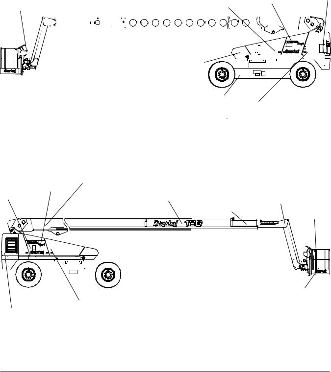
Fuel Tank
Chassis
Steer Wheels
Emergency
Lowering Valve
Right Side
Batteries |
Main Boom |
|
|
Second Intermediate |
|
|
|
Wiring Box |
Boom |
First Intermediate |
Tip Boom |
|
|
||
|
|
Boom |
|
Platform
Jib 
|
|
|
|
|
|
|
|
|
|
|
|
|
|
|
|
|
|
|
|
|
|
|
|
|
|
|
|
|
|
|
|
|
|
|
|
|
|
|
|
|
|
|
|
|
|
|
|
|
|
|
|
|
|
|
|
|
|
|
|
|
|
|
|
|
|
|
|
|
|
|
|
|
|
|
|
|
|
|
|
|
|
|
|
|
|
|
|
|
|
Platform Foot Switch |
|||||||||
|
Steer Wheels |
|
|
|
|
|
|
|
|
|
||||||||||||||
|
|
|
|
|
|
Battery Disconnect |
||||||||||||||||||
Engine |
|
|
|
|
|
Switch |
||||||||||||||||||
|
|
|
|
|
|
|
|
|
|
|
|
|
|
|
Left Side |
|||||||||
TB126J – 0192117EE |
3 |

Chapter 2 – Specifications
Working Envelope
Meters |
|
|
|
|
|
|
|
|
|
|
(Feet) |
|
|
|
|
|
|
|
|
|
|
39.6 |
|
|
|
|
|
|
|
|
|
|
(130) |
|
|
|
|
|
|
|
|
|
|
36.6 |
|
|
|
|
|
|
|
|
|
|
(120) |
|
|
|
|
|
|
|
|
|
|
33.5 |
|
|
|
|
|
|
|
|
|
|
(110) |
|
|
|
|
|
|
|
|
|
|
30.5 |
|
|
|
|
|
|
|
|
|
|
(100) |
|
|
|
|
|
|
|
|
|
|
27.4 |
|
|
|
|
|
|
|
|
|
|
(90) |
|
|
|
|
|
|
|
|
|
|
24.4 |
|
|
|
|
|
|
|
|
|
|
(80) |
|
|
|
|
|
|
|
|
|
|
21.3 |
|
|
|
|
|
|
|
|
|
|
(70) |
|
|
|
|
|
|
|
|
|
|
18.3 |
|
|
|
|
|
|
|
|
|
|
(60) |
|
|
|
|
|
|
|
|
|
|
15.2 |
|
|
|
|
|
|
|
|
|
|
(50) |
|
|
|
|
|
|
|
|
|
|
12.2 |
|
|
|
|
|
|
|
|
|
|
(40) |
|
|
|
|
|
|
|
|
|
|
9.1 |
|
|
|
|
|
|
|
|
|
|
(30) |
|
|
|
|
|
|
|
|
|
|
6.1 |
|
|
|
|
|
|
|
|
|
|
(20) |
|
|
|
|
|
|
|
|
|
|
3 |
|
|
|
|
|
|
|
|
|
|
(10) |
|
|
|
|
|
|
|
|
|
|
0 |
|
|
|
|
|
|
|
|
|
|
3 |
|
|
|
|
|
|
|
|
|
|
(10) |
21.3 |
18.3 |
15.2 |
12.2 |
9.1 |
6.1 |
3.0 |
0 |
3.0 |
6.1 |
|
(70) |
(60) |
(50) |
(40) |
(30) |
(20) |
(10) |
(10) |
(20) |
|
|
|
|||||||||
|
|
|
|
|
|
|
|
|
|
TB126J – 0192117EE |

|
|
|
|
|
|
Chapter 2 – Specifications |
|
General Specifications |
|
|
|
|
|
|
|
Aerial Platform |
|
|
|
Drive System |
|
|
|
Working height |
|
|
40.2 m (132′) |
Standard |
|
|
Four wheel drive |
Maximum platform height |
|
|
38.4 m (126′) |
Gradeability – theoretical |
|
42% |
|
Horizontal reach |
|
|
19.2 m (63′) |
|
|
|
|
Main boom |
|
|
|
Tires |
|
|
|
Articulation |
|
|
-1° to +75° |
Foam filled |
46 cm x 56 cm (18″ x 22″), 18 ply |
||
Extension |
|
|
7.9 m (26′) |
|
|
|
|
Turntable rotation |
|
|
360° continuous |
Electrical System |
|
|
|
Turning radius, inside |
|
|
|
Voltage |
12 V DC negative chassis ground |
||
Axles extended |
|
|
5.8 m (19′) |
Source |
Three - 12 V 550 CCA batteries |
||
Wheelbase |
|
|
3.7 m (12′) |
Fluid recommended |
|
distilled water |
|
Ground clearance |
|
|
33 cm (13″) |
|
|
|
|
Maximum wheel load |
|
|
9571 kg (21,100 lbs) |
Hydraulic System |
|
|
|
Maximum ground pressure |
|
628 kPa (91 psi) |
Maximum pressure |
|
|
|
|
Weight, EVW |
|
|
|
Four wheel drive |
|
19,320 kPa (2,800 psi) |
|
Approximate |
|
19,000 kg (41,800 lbs) |
Reservoir capacity |
|
|
227 l (60 US gal) |
|
Width |
|
|
|
System capacity |
|
|
341 l (90 US gal) |
Axles retracted |
|
|
2.6 m (8′ 6″) |
Maximum operating temperature |
93°C (200°F) |
||
Axles extended |
|
|
3.9 m (12′ 10″) |
Hydraulic fluid recommended |
|
||
Stowed length |
|
|
13.0 m (42′ 9″) |
Above -13°C (10°F) Mobil DTE-13M (ISO VG32) |
|||
Stowed height |
|
|
3.1 m (10′ 4″) |
Below -13°C (10°F) |
Mobil DTE-11M (ISO VG15) |
||
Platform |
|
|
|
Engine |
|
|
|
Dimensions |
|
|
|
Diesel |
|
|
Cummins B3.3 |
Aluminum |
76 cm x 234 cm (30″ x 92″) |
|
|
|
|
||
Rated work load |
|
|
|
Fuel Tank Capacity |
|
|
|
Aluminum 76 cm x 234 cm |
|
272 kg (600 lb) |
Diesel |
|
|
151 l (40 US gal) |
|
Rotation |
|
|
180 degrees |
|
|
|
|
Maximum number of occupants |
2 people |
Ambient Air Temperature Operating Range |
|||||
Optional AC generator |
|
|
220 VAC |
Celsius |
|
|
-18°C to 43°C |
Function Speed |
|
|
|
Fahrenheit |
|
|
0°F to 110°F |
|
|
|
|
|
|
|
|
Turntable rotation |
|
|
|
Maximum Wind Speed |
|
|
|
Booms retracted |
|
165 seconds minimum |
Gust or steady |
|
|
45 km/h (28 mph) |
|
Booms extended |
|
325 seconds minimum |
|
|
|
|
|
Main boom |
|
|
|
Vibration |
|
|
less than 2.5 m/sec2 |
Up |
|
|
|
|
|
|
|
Booms retracted |
|
|
75 to 95 seconds |
Sound Threshold |
|
|
below 97 dB(A) |
Booms extended |
|
|
165 to 180 seconds |
|
|
|
|
Down |
|
|
|
|
|
|
|
Booms retracted |
|
|
75 to 95 seconds |
|
|
|
|
Booms extended |
|
|
165 to 180 seconds |
|
|
|
|
Extend |
|
|
80 to 100 seconds |
|
|
|
|
Retract |
|
|
80 to 100 seconds |
|
|
|
|
Jib Boom |
|
|
|
|
|
|
|
Up |
|
|
8 to 13 seconds |
|
|
|
|
Down |
|
|
10 to 20 seconds |
|
|
|
|
Platform rotation |
|
|
16 to 20 seconds |
|
|
|
|
Drive |
|
|
|
|
|
|
|
Booms down and retracted |
|
|
|
|
|
|
|
High speed, low torque |
|
|
4.8 km/h (3.0 mph) |
|
|
|
|
Mid speed, mid torque |
|
|
2.4 km/h (1.5 mph) |
|
|
|
|
Low speed, high torque |
|
|
1.2 km/h (0.75 mph) |
|
|
|
|
Booms up and/or extended |
|
|
|
|
|
|
|
To mid elevation |
|
|
1.2 km/h (0.75 mph) |
|
|
|
|
Above mid elevation |
|
|
0.06 m/sec (creep) |
|
|
|
|
TB126J – 0192117EE |
5 |
Chapter 2 – Specifications
Engine Specifications
Engine |
Displacement |
Fuel Grade |
Coolant |
Operating |
Oil |
Oil |
|
Temperature |
Capacity |
Grade |
|||||
|
|
|
|
||||
|
|
|
|
|
|
|
|
|
|
Diesel |
|
|
7.5 l (2 gal) |
SAE |
|
|
|
ASTM No. 2D fuel with a |
|
|
|||
Cummins |
3.26 liter |
50% Water |
60°C to 100°C |
15W-403 |
|||
minimum Cetane number of |
total |
|
|||||
B3.3 |
(199 cu. in.) |
40.1 For operating tempera- |
50% Antifreeze2 |
140°F to 212°F |
1.5 l (1.6 qt) |
API: |
|
|
|
tures below 0°C (32°F) use |
|
|
Low to High |
||
|
|
|
|
CH4/SG |
|||
|
|
winterized No. 2D. |
|
|
|
||
|
|
|
|
|
|
||
|
|
|
|
|
|
|
Note 1: Refer to the engine manufacturers manual for specific fuel recommendations and specifications.
Note 2: Ethylene glycol or Propylene glycol may be used. Refer to the Cummins® Operation and Maintenance Manual B3.3 Series Engines for specific coolant recommendations and specifications.
Note 3: Refer to the engine manufacturers manual for specific lubricating oil recommendations and specifications.
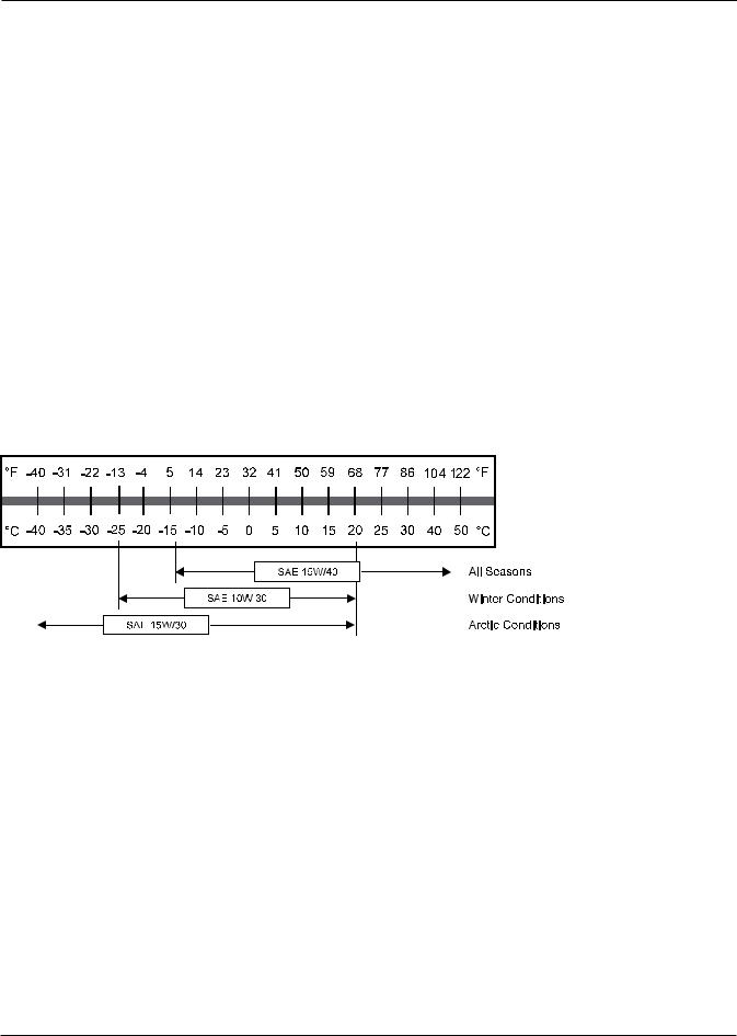
Engine Oil Viscosity
Cummins B3.3
TB126J – 0192117EE
Chapter 3 – Safety
Knowledge of the information in this manual, and proper training, provide a basis for safely operating the aerial platform. Know the location of all controls and how they operate to act quickly and responsibly in an emergency.
Safety devices reduce the likelihood of an accident. Never disable, modify, or ignore any safety device. Safety alerts in this manual indicate situations where accidents may occur.
If any malfunction, hazard or potentially unsafe condition relating to capacity, intended use, or safe operation is suspected, stop aerial platform operation and seek assistance.
The operator bears ultimate responsibility for following all manufacturer’s instructions and warnings, regulations and safety rules of their employer and/or any state or federal law.
Electrocution Hazards
The aerial platform is made of metal components and is not insulated. Regard all conductors as energized. Do not operate outside during a thunderstorm.
Minimum Safe Approach Distance
Minimum safe approach distances to energized power lines and their associated parts must be observed while operating the aerial platform.
ADanger
The aerial platform is not electrically insulated. Death or serious injury can result from contact with, or inadequate clearance from, an energized conductor. Do not go closer than the minimum safe approach distance as defined by ANSI or national safety regulations.
ANSI publications define minimum distances that must be observed when working near bus bars and energized power lines. Table 1 and Figure 3 are reprinted courtesy of Scaffold Industry Association, ANSI/SIA A92.5.
Voltage Range |
Minimum Safe Approach Distance |
|
(Phase to Phase) |
Feet |
Meters |
0 to 300V |
Avoid Contact |
|
Over 300V to 50kV |
10 |
3.05 |
Over 50kV to 200kV |
15 |
4.60 |
Over 200kV to 350Kv |
20 |
6.10 |
Over 350kV to 500kV |
25 |
7.62 |
Over 500kV to 750kV |
35 |
10.67 |
Over 750kV to 1000kV |
45 |
13.72 |
Table 1 – Minimum Safe Approach Distance
Denotes prohibited zone
Figure 3 – Minimum Safe Approach Distance
TB126J – 0192117EE |
7 |

Chapter 3 – Safety
Prestart Inspection
Perform a prestart inspection before each shift as described in Chapter 7. Do not use the aerial platform on the job unless you are trained and authorized to do so.
Always look in the direction of movement. Drive with care and at speeds compatible with the work place conditions. Use caution when driving over rough ground, on slopes and when turning. Do not engage in any form of horseplay or permit riders any place other than in the platform.
Work Place Inspection and Practices
Do not use the aerial platform as a ground connection when welding. The welding ground clamp must be attached to the same structure that is being welded. Electrical current flow can be very intense, causing serious internal damage to some components.
Inspect the area before and during aerial platform use. The following are some potential hazards that may be in the work place.
•Debris
•Slopes
•Drop-offs or holes
•Bumps and floor obstructions
•Overhead obstructions
•Unauthorized persons
•High voltage conductors
•Wind and weather conditions
•Inadequate surface and support to withstand load forces applied by the aerial platform in all operating configurations
Before using the aerial platform in any hazardous (classified) location, make certain it is approved and of the type required for use in that particular location.
Know and understand the job site traffic-flow patterns and obey the flagmen, road signs and signals.
While operating the aerial platform, a good safety practice is to have qualified personnel in the immediate work area to:
•Help in case of an emergency
•Operate emergency controls as required
•Watch for loss of control by platform operator
•Warn the operator of any obstructions or hazards that may not be obvious to them
•Watch for soft terrain, sloping surfaces, drop-offs, etc. where stability could be jeopardized
•Watch for bystanders and never allow anyone to be under, or to reach through the booms while operating the aerial platform
ADanger
Pinch points may exist between moving components. Death or serious injury can result from becoming trapped between components, buildings, structures or other obstacles. Make sure there is sufficientclearancearoundthemachinebeforemoving the chassis, booms, or platform.Allow sufficient room and time to stop movement to avoid contact with structures or other hazards.
Secure all accessories, containers, tools and other materials in the platform to prevent them from accidentally falling or being kicked off the platform. Remove all objects that do not belong in or on the aerial platform.
Never steady the platform by positioning it against another platform.
AWarning
The potential for an accident increases when operating an aerial platform that is damaged or malfunctioning. Death or serious injury can result from such accidents. Do not operate the aerial platform if it is damaged or malfunctioning.
Do not operate the aerial platform if it is damaged or not functioning properly. Qualified maintenance personnel must correct the problem before putting the aerial platform back into service.
Operation
Use three points of support when entering or exiting the platform. For example, use two hands and one foot when climbing into the platform.
Never cover the platform floor grating or otherwise obstruct your view below. Make sure the area below the platform is free of personnel before lowering.
Keep both feet positioned firmly on the platform floor.
Operate the controls slowly and deliberately to avoid jerky and erratic operation. Always stop the controls in neutral before going in the opposite direction.
Do not dismount while the aerial platform is in motion or jump off the platform.
Properly stow the aerial platform and secure it against unauthorized operation at the end of each work day, before transporting, or if it is left unattended.
Tip-Over and Falling Hazards
Operate the aerial platform only on a firm, flat, level surface capable of withstanding all load forces imposed by the aerial platform in all operating conditions. Refer to the General Specifications chart for the maximum wheel load and ground pressure. Raise the booms only when the aerial platform is on level ground.
ADanger
TB126J – 0192117EE

Chapter 3 – Safety
The aerial platform can tip over if it becomes unstable. Death or serious injury can result from a tip-over accident. Do not drive or position the aerial platform for elevated use near any drop-off, hole, slope, soft or uneven ground, or other tip-over hazard. Do not raise the boom in winds above 45 km/h (28 mph).
All platform occupants must wear a fall restraint device connected to a lanyard anchor point.
It is best not to transfer from the platform to another structure or from the structure to the platform, unless that is the safest way to do the job. Judge each situation separately taking the work environment into account. If it is necessary to transfer from the platform to another structure the following guidelines apply:
1.Where possible, place the platform over a roof or walking structure to do the transfer.
2.Transfer your anchorage from one structure to the other before stepping across.
3.Remember that you might be transferring to a structure where personal fall arrest is required.
4.Use the platform entrance, do not climb over or through the guardrails.
Do not operate the aerial platform in windy or gusty conditions. Do not add anything to the aerial platform that will increase the wind loading such as billboards, banners, flags, etc.
Never operate the aerial platform without all parts of the guardrail system in place and the gate closed. Make sure that all protective guards, cowlings, and doors are securely fastened.
Do not exceed the platform capacity as indicated on the platform rating placard on the platform. Do not carry loads that extend beyond the platform guardrails without prior written consent from Snorkel.
Do not operate the aerial platform from trucks, trailers, railway cars, floating vessels, scaffolds, or similar equipment unless the application is approved in writing by Snorkel.
Do not use the aerial platform as a crane, hoist, jack or for any purpose other than to position personnel, tools and materials.
Do not climb on the guardrails or use ladders, planks, or other devices to extend or increase the work position from the platform.
Take care to prevent rope, electrical cords, and hoses, etc., from becoming caught in or on the aerial platform. If the platform or booms becomes caught on an adjacent structure or other obstacle and is prevented from normal motion, reverse the control to free the platform. If control reversal does not free the platform, evacuate the platform before attempting to free it.
Electrical System
Charge the batteries in a well-ventilated area free of flame, sparks, or other hazards that might cause fire or explosion.
Do not operate any of the aerial platform functions while the battery charger is plugged in.
AWarning
Batteries give off hydrogen and oxygen that can combine explosively. Death or serious injury can result from a chemical explosion. Do not smoke or permit open flames or sparks when checking the batteries.
Battery acid can damage the skin and eyes. Serious infection or reaction can result if medical treatment is not given immediately. Wear face and eye protection when working near the batteries.
Batteries contain sulfuric acid that can damage your eyes or skin on contact. Wear a face shield, rubber gloves, and protective clothing when working around batteries.
If acid contacts your eyes, flush immediately with clear water and get medical attention. If acid contacts your skin, wash off immediately with clear water.
Hydraulic System
The hydraulic system contains hoses with hydraulic fluid under pressure.
ADanger
Hydraulic fluid escaping under pressure can have enough force to inject fluid into the flesh. Serious infection or reaction can result if medical treatment is not given immediately. In case of injury by escaping hydraulic fluid, seek medical attention at once.
Do not place your hand or any part of your body in front of escaping hydraulic fluid. Use a piece of cardboard or wood to search for hydraulic leaks.
Engine and Fuel Handling Precautions
Refer to the engine manufacturer’s Operator’s Manual for complete information on safe engine operation, maintenance and specifications.
TB126J – 0192117EE |
9 |

Chapter 3 – Safety
ADanger
Engine exhaust contains carbon monoxide, a poisonous gas that is invisible and odorless. Breathing engine exhaust fumes can cause death or serious illness. Do not run the engine in an enclosed area or indoors without adequate ventilation.
Be careful not to run the diesel fuel tank empty. Bleed the fuel system if air enters the lines between the tank and the injection pump.
Allow the engine to return to idle before shutting the engine off.
Do not smoke or permit open flames while fueling or near fueling operations.
Never remove the fuel cap or fill the fuel tank while the engine is running or hot. Never allow fuel to spill on hot machine components.
Maintain control of the fuel filler nozzle when filling the tank. Spilled fuel is a potential fire hazard.
Do not overfill the fuel tank. Allow room for expansion.
Clean up spilled fuel immediately.
Tighten the fuel tank cap securely. If the fuel cap is lost, replace it with an approved cap from Snorkel. Use of a non-approved cap without proper venting may result in pressurization of the tank.
Never use fuel for cleaning purposes.
For diesel engines, use the correct fuel grade for the operating season.
ACaution
Engine coolant escaping under pressure can cause serious burns. Shut the engine off and let it cool before removing the radiator cap.
Let the engine and radiator cool before adding coolant.
Placards and Decals
The aerial platform is equipped with placards and decals that provide instruction for operation and accident prevention. Do not operate the aerial platform if any placards or decals are missing or not legible.
10 |
TB126J – 0192117EE |

Chapter 4 – Safety Devices
This aerial work platform is manufactured with safety devices, placards, and decals to reduce the likelihood of an accident. For the safety of all personnel, do not disable, modify or ignore any safety device. Safety devices are included in the daily prestart inspection.
AWarning
The potential for an accident increases when safety devices do not function properly. Death or serious injury can result from such accidents. Do not alter, disable, or override any safety device.
If any safety devices are defective, remove the aerial platformfromserviceuntilqualifiedmaintenancepersonnel can make repairs.
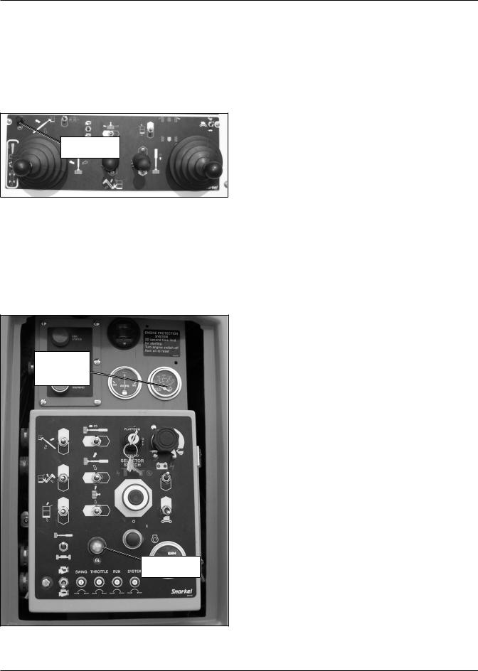
Emergency Stop Controls
There is an emergency stop control at the lower and upper controls.
At the lower controls, the emergency stop is a two-posi- tion push button (refer to Figure 4.1). Push the emergency stop button in to disconnect power to all control circuits. Pull the button out to restore power.
Engine/Emergency
Power Switch
Emergency
Stop Button
Ground
Operation Switch
Figure 4.1 – Lower Controls
Note
The lower controls override the upper controls. If the upper control emergency stop button is engaged, the lower controls can still be used to operate the aerial platform.
At the upper controls, the emergency stop is a two-posi- tion push button (refer to Figure 4.2).
Emergency
Stop Button
Engine/Emergency
Power Switch
Figure 4.2 – Upper Controls
Push the emergency stop button in to disconnect power to the upper control circuits. Pull the button out to restore power.
Emergency Power System
The emergency power system includes a backup pump, motor, and battery. Use this system to operate the boom and turntable functions to lower the platform if the main power system fails due to engine or pump failure.
Hold the emergency power switch (refer to Figures 4.1 and 4.2) down to activate the emergency power system.
The length of time the pump can be operated depends on the capacity of the battery.
Emergency Bleed Down System
The emergency bleed down system may be used to lower the booms if the engine will not start and the emergency power system will not work. The emergency bleed down system is composed of two pairs of toggle switches. (Refer to Figures 4.3 and 4.4) One pair of switches is located on either side of the wiring box. The second pair of switches is located on either side of the upper control box.
Emergency Bleed
Down Switches
Figure 4.3 – Wiring Box
TB126J – 0192117EE |
11 |
Chapter 4 – Safety Devices
Emergency Bleed
Down Switch
Figure 4.4 – Right Side of Upper Controls
Emergency Lowering Knob
The emergency lowering knob may be used to lower the booms if the engine will not start and the emergency power system and bleed down system will not work. The knob is located at the base end of the main boom lift cylinder (refer to Figure 4.5), under the center of the turntable. It is accessible from the underside of the turntable.
Emergency
Lowering Knob
Figure 4.5 – Emergency Lowering Knob
The knob may be turned to open the cylinder bleed down valve for emergency lowering.
Axle/Boom Interlock
The rear axles on the chassis extend to help stabilize the machine when the boom is raised or extended.
The axle/boom interlock prevents the boom from extending and from raising above horizontal if the rear axles are not properly extended and locked in position.
Ground Operation Switch
The ground operation switch (refer to Figure 4.1) prevents boom and platform movement if a control switch on the lower control panel is accidentally moved.
Hold the switch up to operate the machine from the lower controls.
Platform Foot Switch
Stepping down on the platform foot switch (refer to Figure 4.6) activates the upper controls.
|
|
|
|
Top Rail |
|
|
|
|
|
|
|
|
|
Gravity |
|
|
|
|
|
|
Gate |
|
Lanyard |
|
|
|
|
|
Anchors |
|
|
Mid Rail |
||
|
|
|
|
|||
|
|
|
|
|
|
|
Platform Foot
Switch
Toeboard
Figure 4.6 – Platform
The foot switch must be engaged and a control must be moved to operate the boom, drive and/or platform from the upper controls.
Guardrails
The guardrail system includes a top rail, mid rail and toeboards around the sides of the platform (refer to Figure 4.6).
A gravity gate or an optional swinging gate (refer to Figure 4.7) allows for access to the platform.
Figure 4.7 – Optional Swinging Gate
12 |
TB126J – 0192117EE |

Chapter 4 – Safety Devices
The gates close automatically after entering or exiting the platform. The gate is part of the guardrail system and must be securely fastened after entering the platform.
Lanyard Anchors
Two lanyard anchors for fall restraint anchorage are provided below the upper controls at the front of the platform (refer to Figure 4.6).
Note
The lanyard anchors are not for lifting or tying the machine down.
All personnel in the platform must connect their fall restraint device to a lanyard anchor before raising the platform. Do not use the aerial platform for personal fall arrest anchorage.
Envelope Management System
The Envelope Management System (EMS) restricts the movement of the platform to keep it within safe work parameters. There are EMS indicator lights on the upper and lower controls (refer to Figure 4.8).
EMS Indicator |
Green |
Lights |
|
|
White |
|
Red |
Green |
|
White |
EMS Indicator |
|
Lights |
Red |
|
Figure 4.8 – EMS Indicator Lights
A flashing green EMS light indicates the machine is in need of calibration. A Snorkel authorized service provider must be contacted before any further operation. A solid green light indicates system operation is normal.
The white EMS light will begin to flash as the platform approaches the edge of the working envelope. A solid white light indicates the edge of the working envelope has been reached. In the advent of a solid white light, the EMS will restrict one or more types of movement to keep the platform within the working envelope.
The red EMS light/button will only be lit in the case of a malfunction with the EMS system. The red button/light will flash and beep in quick pulses then pause and repeat if the primary envelope has been exceeded. When the red button/light emits a continuous series of beeps and flashes, the primary and backup envelopes have been exceeded. The display of a solid red light, with solid tone, is indicative of system or electrical failures or further extension beyond the backup envelope. If, after resetting the EMS system, the solid red light reoccurs, a Snorkel authorized service provider must be contacted before any further operation.
When the machine is first started or after the EMS has been reset, there will be a 7 to 10 second delay before the EMS system will be operational. During this delay period the green light will not be on and the EMS functions will not be operational.
Height Restriction
The EMS has a height restriction feature which allows the machine owner to limit the maximum height the platform will reach. The maximum height display is located on the wiring box on the left side of the machine (refer to Figure 4.9). If the height has been restricted the word LIMIT will be displayed in the lower right corner.
Limit Indicator
Figure 4.9 – Wiring Box
Tilt Alarm
If the aerial platform chassis is out of level more than 3.5 degrees when the main boom is raised or extended, an alarm will sound. The tilt alarm is located under the upper control panel.
ADanger
The aerial platform can tip over if it becomes unstable. Death or serious injury can result from a tip-over accident. Do not drive or position the aerial platform for elevated use near any drop-off, hole, slope, soft or uneven ground, or other tip-over hazard.
When the tilt alarm sounds, completely retract and lower the main boom and then drive to a level surface. The tilt alarm is for added protection and does not justify operating on anything other than firm, flat, level surfaces.
TB126J – 0192117EE |
13 |
Chapter 4 – Safety Devices
Platform Overload Sensing System
All functions are stopped from the upper and lower controls, when the platform overload limit is exceeded. The horn will sound intermittently and the red overload light (refer to Figure 4.10) will blink until the excess load is removed from the platform. At that time, the machine functions are again operational.
Platform
Overload Light
Figure 4.10 – Upper Controls
If the platform becomes significantly overloaded, or if an upward force on the platform exceeds approximately 445 N (100 lb), the system will enter into error mode, stopping all functions from the upper and lower controls. The horn will then sound constantly and the overload light will stay illuminated at the upper and lower controls (refer to Figures 4.10 and 4.11).
Engine
Temperature
Gauge
Platform
Overload Light
Figure 4.11 – Lower Control Panel
The system will remain in error mode until the excess load is removed from the platform and the emergency stop button or start switch is cycled off and back on, resetting the system. At that time, the machine functions are operational.
ACaution
The emergency power system is for emergency lowering and stowing only. The length of time the pump can be operated depends on the capacity of the battery. Do not use this system for normal operation.
If the platform overload sensing system is tripped while operating the machine or if the system is in error mode and can not be reset, the emergency power system may still be used for emergency machine operation from either the lower or upper controls.
ADanger
The aerial platform can tip over if it becomes unstable. Death or serious injury will result from a tip-over accident. Do not exceed the capacity values indicated on the platform rating placard.
The overload sensing system is not active when the machine is being driven with the booms in the stowed position. This allows the machine to be driven without the system sensing an overload due to rough ground conditions.
To eliminate repeated tripping of the system during machine operation, there is a five second delay in machine functions following:
•starting the engine.
•placing the drive/boom selector switch in the boom position when the main boom is below horizontal and fully retracted.
•removing excess load from the platform.
Engine Protection Systems
A light in the emergency stop button will illuminate to warn against high engine temperature.
The engine will shutdown if the operating temperature exceeds a preset level or if the oil pressure is too low for safe operation. An engine temperature gauge is on the top of the lower control panel (refer to Figure 4.11).
High Engine Temperature Alarm
If the coolant exceeds the engine operating temperature, a light in the emergency stop button will illuminate and the engine will shut off.
Do not restart the engine until the condition that caused the overheating has been corrected.
14 |
TB126J – 0192117EE |
Chapter 4 – Safety Devices
Low Oil Pressure Alarm
The low pressure oil alarm sounds when the engine oil pressure is near the lower limit for safe engine operation. If the alarm sounds, lower the platform to the ground and then turn the engine off. Do not restart the engine until the condition that caused the low oil pressure has been corrected.
If the engine oil pressure falls below a safe operating value the engine will shut off. The engine can be restarted with low oil pressure, but it will only run a few seconds before it shuts off again.
Horn
The horn may be used to warn personnel on the ground. The horn button is on the right side of the upper control panel (refer to Figure 4.12). The horn is operational when the emergency stop button and the start switches are both on at the lower and the upper controls.
Horn Button
Figure 4.12 – Upper Control Panel Front
Drive Motion Alarm
An optional drive motion alarm may be provided on the machine. When the drive/steer control is moved out of neutral the alarm sounds, in short beeps, to warn personnel in the work area to stand clear.
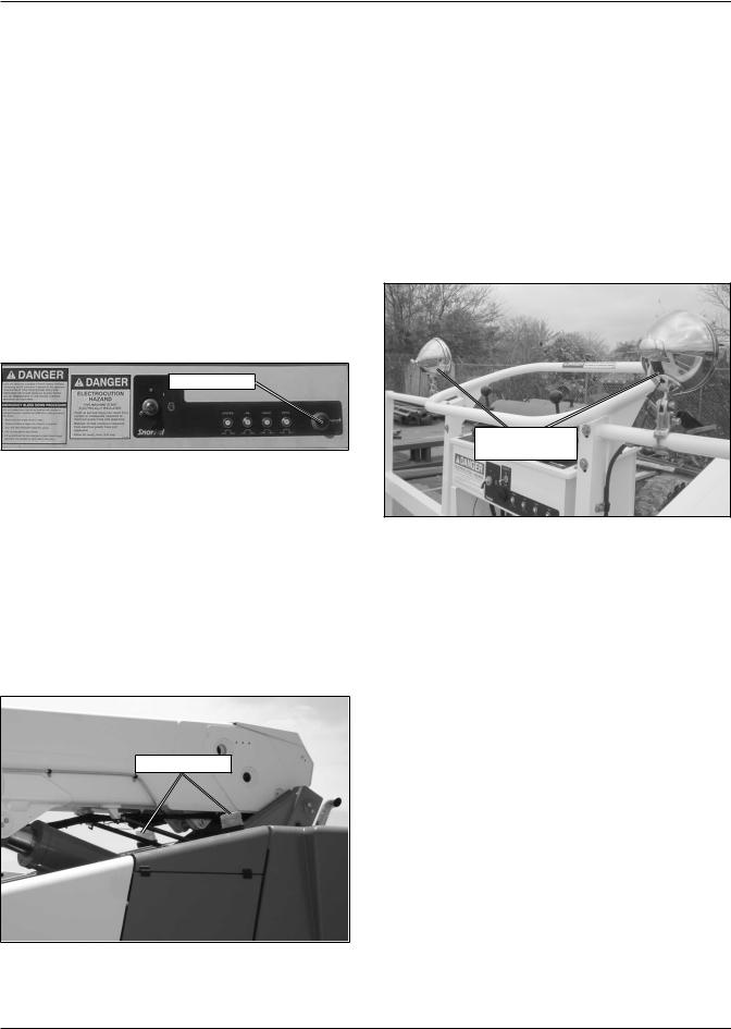
Flashing Light
Optional amber flashing lights may be located on the top rear of the cowling, on either side of the extension cylinder. The flashing lights warn personnel that the aerial platform is in the area.
Driving Lights
Optional headlights and blinking tail lights may be installed on the machine. The headlights are located on the top of the front cowling. The tail lights are mounted on the sides of the rear cowling.
Driving lights help improve visibility while driving the aerial platform and help others see it too. Driving lights are not for driving on public roadways.
Platform Work Lights
Optional platform work lights may be located on the top rail of the platform (refer to Figure 4.14), one on each side of the upper control panel.
Platform Work
Lights
Figure 4.14 – Platform Work Light
Use the platform lights to improve visibility while working aloft in dimly lit areas. Do not use the platform work lights to drive on public roadways.
Flashing Lights
Figure 4.13 – Flashing Lights
The lights flash at about one flash per second when the engine is running.
TB126J – 0192117EE |
15 |

Chapter 4 – Safety Devices
16 |
TB126J – 0192117EE |
Chapter 5 – Gauges and Displays
The aerial platform is equipped with several gauges to monitor the condition of the machine before and during operation.
Hour Meter
The hour meter is located on the lower control panel (refer to Figure 5.1). It measures the accumulated engine operating time.
|
Engine |
|
Temperature |
Ammeter |
Gauge |
|
Hour Meter
Figure 5.1 – Lower Controls
Engine Temperature Gauge
The temperature gauge is located on the lower control panel (refer to Figure 5.1). The gauge displays the temperature of the water and antifreeze mixture in the engine block.
Ammeter
The ammeter is located on the lower control panel (refer to Figure 5.1). The ammeter displays the level of current flow from the alternator to the batteries.
After the engine has been running for a few minutes under normal operating conditions, the ammeter gauge indicator should read approximately “0.”
Engine Air Filter Gauge
The air filter gauge (refer to Figure 5.2) is located above the lower control panel. The gauge measures the air pressure between the intake manifold and the air filter.
Air Filter Gauge
Reset Button
Figure 5.2 – Air Filter Gauge
The yellow indicator disk inside the sight glass stays at its highest level when the engine is turned off.
When the yellow indicator disk reaches the red area, it’s time to change the filter element. After changing the filter, press the reset button to reset the indicator disk to the bottom of the sight glass.
Fuel
The fuel tank is translucent. The amount of fuel in the tank can be gauged by raising the door on the right rear of the machine (refer to Figure 5.3) and looking at the tank.
Fuel Tank
Figure 5.3 – Fuel Tank
Note
Do not run a diesel fuel tank empty. Air in the fuel line makes the engine hard to start.
TB126J – 0192117EE |
17 |
 Loading...