


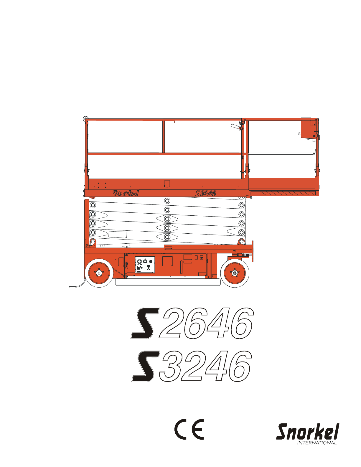
S3246 CE
OperOper
OperOper
Oper
aa
aa
a
tor’tor’
tor’tor’
tor’
ss
ss
s
ManualManual
ManualManual
Manual
Part Number 0410063EE
July, 2005

The aerial platform is not electrically insulated. Death or serious injury will result from con-
tact with, or inadequate clearance from, an energized conductor.
Do not go closer than the minimum safe approach distance as defined by the Minimum Safe
Approach Distance section in Chapter 3 – Safety.
Regard all conductors as energized.
Allow for electrical wire sag and aerial platform sway .
If the platform, scissors structure, or any part of the aerial platform contacts a high-voltage electrical
conductor, the entire machine can become electrically charged.
If that happens, remain on the machine and do not contact any other structure or object. This includes
the ground, adjacent buildings, poles, and any other objects that are not part of the aerial platform.
Such contact could make your body a conductor to the other object, creating an electrical shock
hazard resulting in death or serious injury .
If an aerial platform is in contact with an energized conductor the platform operator must warn ground
personnel in the vicinity to stay away . Their bodies can conduct electricity creating an electrical shock
hazard resulting in death or serious injury .
Do not approach or leave the aerial platform until the electricity has been turned off.
Do not attempt to operate the lower controls when the platform, scissors structure, or any part of the
aerial platform is in contact with a high-voltage electrical conductor or if there is an immediate danger
of such contact.
Personnel on or near an aerial platform must be continuously aware of electrical hazards, recognizing
that death or serious injury can result from contact with an energized conductor .

S2646/3246 – 0410063EE
Table of Contents
Chapter 1 – Introduction
Aerial Platform Features............................................ 1
Options .....................................................................1
Operator’s Manual..................................................... 1
Safety Alerts ............................................................. 1
Operation .................................................................. 1
Maintenance .............................................................2
Owner and User Responsibilities............................... 2
Additional Information ................................................2
Chapter 2 – Specifications
Component Identification ...........................................3
General Specifications S2646....................................4
Aerial Platform ....................................................... 4
Platform ................................................................. 4
Function Speed...................................................... 4
Drive System ......................................................... 4
Drive/Lift Level Sensor Interlock.............................. 4
Tires ...................................................................... 4
Electrical System .................................................. 4
Hydraulic System .................................................. 4
Ambient Air T emperature Operating Range............. 4
Maximum Wind Speed........................................... 4
Vibration ................................................................ 4
Sound Threshold .................................................... 4
General Specifications S3246....................................5
Aerial Platform ....................................................... 5
Platform ................................................................. 5
Function Speed...................................................... 5
Drive System ......................................................... 5
Drive/Lift Level Sensor Interlock.............................. 5
Tires ...................................................................... 5
Electrical System .................................................. 5
Hydraulic System .................................................. 5
Ambient Air T emperature Operating Range............. 5
Maximum Wind Speed........................................... 5
Vibration ................................................................ 5
Sound Threshold .................................................... 5
Chapter 3 – Safety
Electrocu tion Hazards...............................................7
Minimum Safe Approach Distance.............................7
Prestart Inspection ....................................................8
Work Place Inspection and Practices........................8
Operation .................................................................. 8
Tip-Over and Falling Hazards.....................................8
Electrical System ...................................................... 9
Hydraulic System......................................................9
Placards and Decals .................................................9
Chapter 4 – Safety Devices
Emergency Stop Controls ....................................... 11
Drive Motion Alarm .................................................. 11
Pothole Protector Skids .......................................... 1 1
Drive/Lift Pothole Protector Interlock........................ 12
Drive/Lift Level Sensor Interlock ...............................12
Lowering Alarm........................................................ 12
Lowering Interrupt.................................................... 12
Emergency Lowering Handle ...................................12
Safety Prop .............................................................12
Guardrails ............................................................... 13
Horn ........................................................................ 13
Tilt Alarm.................................................................13
Overload Protection .................................................13
Flashing Light ......................................................... 13
Chapter 5 – Gauges and Displays
Hour Meter .............................................................. 15
Ammeter .................................................................15
Battery Condition Indicator ...................................... 15
Chapter 6 – Batteries
General Maintenance .............................................. 17
Charging ................................................................. 17
Chapter 7 – Controls
Battery Disconnect Switch ...................................... 19
Lower Controls ........................................................ 19
Emergency Stop Button....................................... 19
Control Selector Switch ....................................... 19
Platform Raise/Lower Switch ............................... 19
Upper Controls ........................................................ 19
Emergency Stop Button....................................... 20
Drive/Lift Selector Switch ..................................... 20
Joystick ............................................................... 20
Interlock............................................................... 20
Steer Switch ........................................................ 20
Drive Range Switch .............................................. 20
Horn Button ......................................................... 20
Battery Condition Indicator ................................... 20
Chapter 8 – Prestart Inspection
Operator’s Manual................................................... 21
Electrical System .................................................... 21
Battery Fluid Level ............................................... 21
Battery T erminals................................................. 21
Battery Charger.................................................... 21
Safety Prop .............................................................22
Cables and Wiring Harness..................................... 22
Hydraulic System....................................................23
Fluid Level............................................................ 23
Hoses and Fittings............................................... 23
Free-Wheeling V alve ............................................ 23
Tires and Wheels ....................................................24
Ground Strap........................................................... 24
Lower Control Station ..............................................24
Operating Controls ............................................... 24
Emergency Stop .................................................. 24

Table of Contents
S2646/S3246 – 0410063EE
Lowering Alarm and Interrupt ...................................24
Pothole Protector Interlock ......................................24
Emergency Lowering............................................... 25
Structures ............................................................... 25
Weldments .......................................................... 25
Slide Pads ........................................................... 26
Fasteners ............................................................ 26
Upper Control Station ..............................................26
Guardrail System................................................. 26
Platform Extension .............................................. 26
Swing-Down Rails ................................................ 27
Brakes ................................................................. 27
Operating Controls ............................................... 27
Emergency S top .................................................. 27
Horn..................................................................... 27
Lowering Alarm and Interrupt ...................................28
Drive Motion Alarm ..................................................28
Flashing Light ......................................................... 28
Battery Condition Indicator ...................................... 28
Placards and Decals ...............................................28
Prestart Inspection Checklist .................................. 31
Chapter 9 – Operation
Preparing for Operation............................................33
Lower Controls ........................................................ 33
Upper Controls ........................................................ 33
Driving ..................................................................... 34
Drive Range Switch .............................................. 34
Drive S peeds ........................................................ 34
Drive/Lift Level Sensor Interlock............................ 35
Steering...................................................................35
Platform .................................................................. 35
Raising and Lowering ........................................... 35
Lowering Interrupt................................................. 35
Overload Protection.............................................. 35
Extending ............................................................ 36
Swing-Down Rails ................................................ 36
Swing-Out Trays ..................................................... 37
Wallboard Loading .................................................. 37
Chapter 10 – Stowing and Transporting
Stowing ...................................................................39
Transporting ............................................................ 39
Lifting With a Forklift ............................................ 39
Winching ............................................................. 39
Driving.................................................................. 40
Hoisting ............................................................... 41
Securing for Transport.......................................... 42
Chapter 1 1 – Emergency Operation
Emergency Lowering............................................... 43
Towing..................................................................... 43
Chapter 12 – Troubleshooting
Troubleshooting Chart ............................................. 45
Appendix A – Glossary
Limited Warranty

S2646/S3246 – 0410063EE 1
Chapter 1 – Introduction
Aerial Platform Features
The aerial platform is a self-propelled scissors lift that
has been designed to raise personnel, their tools, and
material to the workstation. The S2646 has one hydrau-
lic cylinder to raise and lower the platform and the S3246
has two cylinders. A hydraulic motor on each of the front
wheels provides power to move the aerial platform.
The standard machine includes the following features.
• Proportional drive and lift up control
• Drivable at full height
• Drive motion alarm
• Non-marking tires
• Automatic pothole protection system
• Level sensor with drive/lift interlock
• Hour meter
• Manual lowering valve
• Lockable battery disconnect switch
• Tie-down lugs
• Lifting lugs
• Heavy duty battery charger with ammeter
• Swing-out hydraulic and electrical component trays
• Non-slip metal platform floor
• 0.9 m (3′) platform extension
• Swing-down platform rails
• 125 volt AC electrical outlet with GFCI
• Scissor arm safety support prop
• Lowering alarm
• Removable upper controls
• Horn
• Forklift loadable from three sides
• Rear forklift pockets
• Platform entry gate with gravity gate
• Keyed control selector switch
• Five year limited warranty
The aerial platform has been manufactured to conform to
European Directive 98/37/EC and European Standard
EN280.
Options
The following options may be provided on the machine.
• Flashing light
• Battery condition indicator
Operator’s Manual
This manual provides information for safe and proper op-
eration of the aerial platform. Because it covers more
than one model, some figures may only represent what
is actually on the machine. Read and understand the
information in this Operator’s Manual before operating
the aerial platform on the job.
Additional copies of this manual may be ordered from
Snorkel. Supply the model and manual part number from
the front cover to assure that the correct manual will be
supplied.
All information in this manual is based on the latest prod-
uct information at the time of publication. Snorkel reserves
the right to make product changes at any time without
obligation.
Safety Alerts
A safety alert symbol is used throughout this manual to
indicate danger, warning, and caution instructions. Fol-
low these instructions to reduce the likelihood of per-
sonal injury and property damage. The terms danger,
warning, and caution indicate varying degrees of personal
injury or property damage that can result if the instruc-
tion is not followed.
ADanger
Indicates an imminently hazardous situation which,
if not avoided, will result in death or serious injury .
This signal word is to be used in the most extreme
situations.
AWarning
Indicates a potentially hazardous situation which, if
not avoided, could result in death or serious injury .
ACaution
Indicates a potentially hazardous situation which, if
not avoided, may result in minor or moderate in-
jury. It may also be used to alert against unsafe
practices.
Notes
Notes are used to provide special information or helpful
hints to assist in aerial platform operation, but do not
indicate a hazardous situation.
Operation
The aerial platform has built-in safety features and has
been factory tested for compliance with Snorkel specifi-
cations and industry standards. However , any personnel
lifting aerial platform can be potentially dangerous in the
hands of untrained or careless operators.
AWarning
The potential for an accident increases when the
aerial platform is operated by personnel who are
not trained and authorized. Death or serious injury
can result from such accidents. Read and under-
stand the information in this manual and on the plac-
ards and decals on the machine before operating
the aerial platform on the job.
Training is essential and must be performed by a quali-
fied person. Become proficient in knowledge and actual
operation before using the aerial platform on the job. Y ou
must be trained and authorized to perform any functions
of the aerial platform. Operation of the aerial platform must
be within the scope of the machine specifications.

Chapter 1 – Introduction
2 S2646/S3246 – 0410063EE
The operator bears ultimate responsibility for following all
manufacturer’s instructions and warnings, regulations and
safety rules of their employer and/or any state or federal
law.
Maintenance
Every person who maintains, inspects, tests, or repairs
the aerial platform must be qualified to do so. Following
the daily prestart inspection in this Operator’s Manual
will help keep the aerial platform in optimum working con-
dition. Other maintenance functions must be performed
by maintenance personnel who are qualified to work on
the aerial platform.
Do not modify this aerial platform without prior written
consent of the Snorkel Engineering Department. Modifi-
cation may void the warranty, adversely af fect stability , or
affect the operational characteristics of the aerial plat-
form.
Owner and User Responsibilities
All owners and users of the aerial platform must read,
understand, and comply with all applicable regulations.
Ultimate compliance to national safety regulations is the
responsibility of the user and their employer.
Additional Information
For additional information contact your local dealer or
Snorkel at:
Snorkel International
P.O. Box 1160
St. Joseph, MO 64502-1160 USA
785-989-3000
http://www.snorkelusa.com
S2646/S3246 – 0410063EE 3
Chapter 2 – Specifications
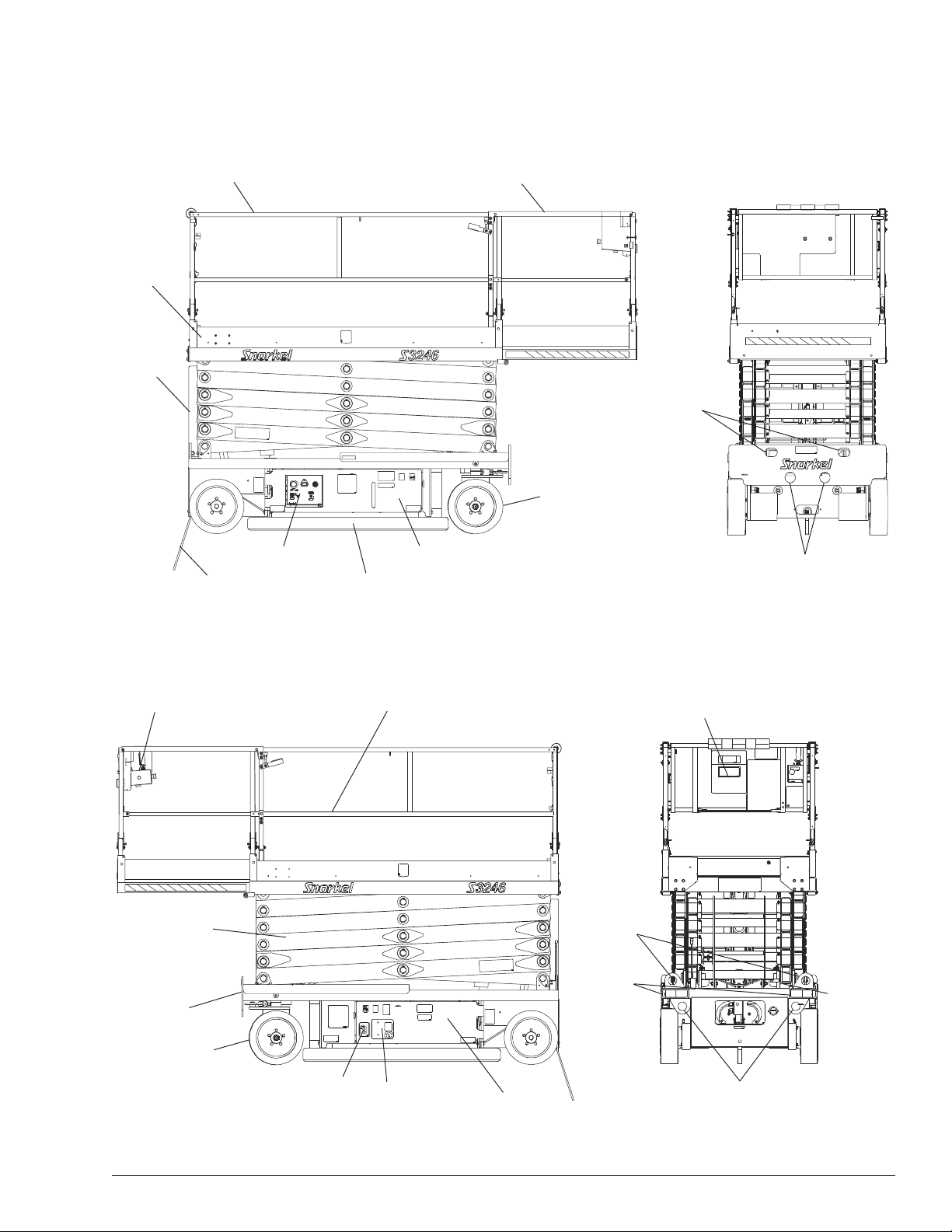
Component Identification
Chassis
Battery Charger
Upper Controls
Platform
Platform Extension Deck
Left Side
Battery Tray
Battery Disconnect
Switch
Pothole Protector Skid
Operator’s
Manual
Scissors
Structure
Guardrails
Toeboards
Entry Step
Ground Strap
Right Side
Rear
Front
Lower Controls
Hydraulic Tray
Lifting Lugs
Tie-down Lugs
Drive and Steer
Wheels
Drive and Steer
Wheels
Forklift
Pockets
Lifting Lugs
Emergency
Lowering
Handle
Tie-down Lugs

Chapter 2 – Specifications
4 S2646/S3246 – 0410063EE
General Specifications S2646
Aerial Platform
Working height 9.75 m (32′)
Maximum platform height 7.9 m (26′)
Turning radius
Inside 25.4 cm (10″)
Outside 2.5 m (101″)
Wheelbase 1.9 m (75″)
Ground clearance
Pothole protector raised 10.1 cm (4″)
Pothole protector lowered 2.5 cm (1″)
Maximum wheel load 1 125 kg (2,480 lbs)
Maximum ground pressure 11.7 kg/cm² (166 p si)
Weight, GVW
Approximate 2359 kg (5,200 lbs)
Stowed wid th 1 16.8 cm (46″)
Stowed length 254 cm (100″)
Stowed height
Guardrails raised 236.2 cm (93″)
Guardrails lowered 167.6 cm (66″)
Platform
Dimensions
Main 1 14.3 cm x 238.7 cm (45″ x 94″)
Extension 104.1 cm x 91.4 cm (41″ x 36″)
Total length with extension 330.2 cm (130″)
Rated work load
Total 453.5 kg (1,000 lb)
Extension 113.3 kg (250 lb)
Maximum number of occupants
Outside 1 person
Inside 3 people
Function Speed
Platform raise 25 to 35 seconds
Platform lower 50 to 60 seconds
High drive
Platform lower than 2.1 to 2.4 m (7 to 8 feet)
3.2 km/h (0 to 2 mph)
Low drive
Platform higher than 2.1 to 2.4 m (7 to 8 feet)
0.8 km/h (0 to 0.5 mph)
Drive System
St andard Two wheel drive
Gradeability 25%
Maximum drive height 10.9 m (26′)
Drive/Lift Level Sensor Interlock
Side-to-side 2 degrees
Front-to-rear 4 degrees
Tires
Nonmarking solid rubber 40.6 cm x 12.7 cm (16″ x 5″)
Electrical System
V olta ge 24 V DC negative chassis ground
Source Four - 6 V 240 amp hour batteries
Fluid recommended distilled water
Charger 40 amp
Hydraulic System
Maximum pressure 21,373.75 kPa (3,100 psi)
Reservoir capacity 34 l (9 US gal)
System capacity 35 l (9.25 US gal)
Maximum operating temperature 71°C (160°F)
Hydraulic fluid recommended
Above -13°C (10°F) Mobil DTE-13M (ISO VG32)
Below -13°C (10°F) Mobil DTE-11M (ISO VG15)
Ambient Air Temperature Operating Range
Celsius -18°C to 43°C
Fahrenheit 0°F to 1 10°F
Maximum Wind Speed
Gust or steady 12.5 m/s (28 mph)
Vibration less than 2.5 m/sec
2
Sound Threshold below 70 dB(A)

Chapter 2 – Specifications
S2646/S3246 – 0410063EE 5
General Specifications S3246
Aerial Platform
Working height 1 1.58 m (38′)
Maximum platform height 9.75 m (32′)
Turning radius
Inside 25.4 cm (10″)
Outside 2.5 m (101″)
Wheel base 1.9 m (75″)
Ground clearance
Pothole protector raised 10.1 cm (4″)
Pothole protector lowered 2.5 cm (1″)
Maximum wheel load 1328 kg (2,928 lbs)
Maximum ground pressure 13.8 kg/cm² (196 psi)
Weight, GVW
Approximate 3003 kg (6,620 lbs)
Stowed wid th 1 16.8 cm (46″)
Stowed length 254 cm (100″)
Stowed height
Guardrails raised 251.4 cm (99″)
Guardrails lowered 182.8 cm (72″)
Platform
Dimensions
Main 45″ x 94″ (1 14.3 cm x 238.7 cm)
Extension 41″ x 36″ (104.1 cm x 91.4 cm)
Total length with extension 130″ (330.2 cm)
Rated work load
T otal 317.5 kg (700 lb)
Extension 113.3 kg (250 lb)
Maximum number of occupants
Outside 1 person
Inside 2 people
Function Speed
Platform raise 40 to 50 seconds
Platform lower 50 to 60 seconds
High drive
Platform lower than 2.1 to 2.4 m (7 to 8 feet)
3.2 km/h (0 to 2 mph)
Low drive
Platform higher than 2.1 to 2.4 m (7 to 8 feet)
0.8 km/h (0 to 0.5 mph)
Drive System
Standard Two wheel drive
Gradeability 25%
Maximum drive height 9.75 m (32′)
Drive/Lift Level Sensor Interlock
Side-to-side 2 degrees
Front-to-rear 4 degrees
Tires
Nonmarking solid rubber 40.6 cm x 12.7 cm (16″ x 5″)
Electrical System
Vo ltage 24 V DC negative chassis ground
Source Four - 6 V 240 amp hour batteries
Fluid recommended distilled water
Charger 40 amp
Hydraulic System
Maximum pressure 21,373.75 kPa (3,100 psi)
Reservoir capacity 34 l (9 US gal)
System capacity 35 l (9.25 US gal)
Maximum operating temperature 71°C (160°F)
Hydraulic fluid recommended
Above -13°C (10°F) Mobil DTE-13M (ISO VG32)
Below -13°C (10°F) Mobil DTE-11M (ISO VG15)
Ambient Air Temperature Operating Range
Celsius -18°C to 43°C
Fahrenheit 0°F to 110°F
Maximum Wind Speed
Gust or steady 12.5 m/s (28 mph)
Vibration less than 2.5 m/sec
2
Sound Threshold below 70 dB(A)

Chapter 2 – Specifications
6 S2646/S3246 – 0410063EE
S2646/S3246 – 0410063EE 7
Chapter 3 – Safety
Knowledge of the information in this manual, and proper
training, provide a basis for safely operating the aerial
platform. Know the location of all controls and how they
operate to act quickly and responsibly in an emergency .
Safety devices reduce the likelihood of an accident. Never
disable, modify, or ignore any safety device. Safety alert s
in this manual indicate situations where accidents may
occur.
If any malfunction, hazard or potentially unsafe condition
relating to capacity, intended use, or safe operation is
suspected, stop aerial platform operation and seek as-
sistance.
The operator bears ultimate responsibility for following all
manufacturer’s instructions and warnings, regulations and
safety rules of their employer and/or any state or federal
law.
Electrocution Hazards
The aerial platform is made of metal components and is
not insulated. Regard all conductors as energized. Do
not operate outside during a thunderstorm.
Minimum Safe Approach Dist ance
Minimum safe approach distances to energized power
lines and their associated parts must be observed while
operating the aerial platform.
ADanger
The aerial platform is not electrically insulated.
Death or serious injury will result from contact with,
or inadequate clearance from, an energized con-
ductor. Do not go closer than the minimum safe
approach distance as defined by ANSI or national
safety regulations.
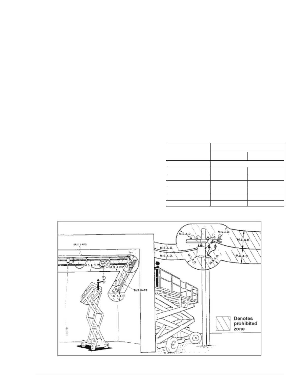
ANSI publications define minimum distances that must
be observed when working near bus bars and energized
power lines. T able 1 and Figure 4 are reprinted courtesy
of Scaffold Industry Association, ANSI/SIA A92.6.
Table 1 – Minimum Safe Approach Distance
Figure 4 – Minimum Safe Approach Distance
Minimum Safe Approach Distance
V oltage Range
(Phase to Phase)
0 to 300V
Over 300V to 50kV
Over 50kV to 200kV
Over 200kV to 350kV
Over 350kV to 500kV
Over 500kV to 750kV
Over 750kV to 1000kV
Feet Meters
Avoid Contact
10
15
25
20
35
45
3.05
4.60
6.10
7.62
10.67
13.72

Chapter 3 – Safety
8 S2646/S3246 – 0410063EE
Prestart Inspection
Perform a prestart inspection before each shift as de-
scribed in Chapter 8. Do not use the aerial platform on
the job unless you are trained and authorized to do so.
Work Place Inspection and Practices
Do not use the aerial platform as a ground connection
when welding. The welding ground clamp must be at-
tached to the same structure that is being welded. Elec-
trical current flow can be very intense, causing serious
internal damage to some components.
Inspect the area before and during aerial platform use.
The following are some potential hazards that may be in
the work place.
• Debris
• Slopes
• Drop-offs or holes
• Bumps and floor obstructions
• Overhead obstructions
• Unauthorized persons
• High voltage conductors
• Wind and weather conditions
• Inadequate surface and support to withstand load
forces applied by the aerial platform in all operating
configurations
Before using the aerial platform in any hazardous (classi-
fied) location, make certain it is approved and of the type
required by ANSI/NFPA 505 for use in that particular lo-
cation.
Know and understand the job site traffic-flow patterns and
obey the flagmen, road signs, and signals.
While operating the aerial platform, a good safety prac-
tice is to have qualified personnel in the immediate work
area to:
• Help in case of an emergency.
• Operate emergency controls as required.
• Watch for loss of control by platform operator.
• Warn the operator of any obstructions or hazards
that may not be obvious to them.
• Watch for soft terrain, sloping surfaces, drop-offs, etc.
where stability could be jeopardized.
• Watch for bystanders and never allow anyone to be
under the platform, or to reach through the scissor
arms while operating the aerial platform.
ADanger
Pinch points may exist between moving compo-
nents. Death or serious injury will result from be-
coming trapped between components, buildings,
structures, or other obstacles. Make sure there is suf-
ficient clearance around the machine before mov-
ing the chassis or platform. Allow sufficient room
and time to stop movement to avoid contact with
structures or other hazards.
Always look in the direction of movement. Drive with care
and at speeds compatible with the work place conditions.
Use caution when driving over rough ground, on slopes,
and when turning. Do not engage in any form of horse-
play or permit riders any place other than in the platform.
Secure all accessories, containers, tools, and other ma-
terials in the platform to prevent them from accidentally
falling or being kicked off the platform. Remove all ob-
jects that do not belong in or on the aerial platform.
Never steady the platform by positioning it against an-
other platform.
Do not operate the aerial platform if it is damaged or not
functioning properly. Qualified maintenance personnel must
correct the problem before putting the aerial platform back
into service.
Operation
Use three points of support when entering or exiting the
platform. For example, use two hands and one foot when
climbing into the platform.
Make sure the area below the platform is free of person-
nel before lowering.
Keep both feet positioned firmly on the platform floor.
Operate the controls slowly and deliberately to avoid jerky
and erratic operation. Always stop the controls in neutral
before going in the opposite direction.
Do not dismount while the aerial platform is in motion or
jump off the platform.
Properly stow the aerial platform and secure it against
unauthorized operation at the end of each work day , be-
fore transporting, or if it is left unattended.
Tip-Over and Falling Hazards
Operate the aerial platform only on a firm, flat, level sur-
face capable of withstanding all load forces imposed by
the aerial platform in all operating conditions. Refer to the
General Specifications chart for the maximum wheel load,
maximum floor pressure, and drive/lift level sensor inter-
lock information. Raise the platform only when the aerial
platform is on level ground.
ADanger
The aerial platform can tip over if it becomes un-
stable. Death or serious injury will result from a tip-
over accident. Do not drive or position the aerial
platform for elevated use near any drop-off, hole,
slope, soft or uneven ground, or other tip-over haz-
ard. Do not raise the platform in wind speeds above
12.5 m/s (28 mph).
Do not operate the aerial platform within 1.2 m (4′) of any
drop-off or hole.

Chapter 3 – Safety
S2646/S3246 – 0410063EE 9
Do not raise the platform in winds above 12.5 m/s (28
mph).
Do not add anything to the aerial platform that will in-
crease the wind loading such as billboards, banners, flags,
etc.
Never operate the aerial platform without all parts of the
guardrail system in place. Make sure the platform gate
and the gravity gate are closed. Make sure that all pro-
tective guards, cowlings, and doors are securely fastened.
Do not exceed the platform capacity as indicated on the
platform rating placard on the platform. Do not carry loads
that extend beyond the platform guardrails without prior
written consent from Snorkel.
Do not operate the aerial platform from trucks, trailers,
railway cars, floating vessels, scaffolds, or similar equip-
ment unless the application is approved in writing by
Snorkel.
Do not use the aerial platform as a crane, hoist, jack, or
for any purpose other than to position personnel, tools,
and materials.
Do not climb on the guardrails or use ladders, planks, or
other devices to extend or increase the work position
from the platform.
Take care to prevent rope, electrical cords, and hoses,
etc., from becoming caught in or on the aerial platform. If
the platform or scissors structure becomes caught on an
adjacent structure or other obstacle and is prevented from
normal motion, reverse the control to free the platform. If
control reversal does not free the platform, evacuate the
platform before attempting to free it.
It is best not to transfer from the platform to another struc-
ture or from the structure to the platform, unless that is
the safest way to do the job. Judge each situation sepa-
rately taking the work environment into account. If it is
necessary to transfer from the platform to another struc-
ture the following guidelines apply:
1. If you are using a fall restraint, transfer your anchor-
age from one structure to the other before stepping
across.
2. Remember that you might be transferring to a struc-
ture where personal fall arrest is required.
3. Use the platform entrance, do not climb over or
through the guardrails.
Electrical System
Charge the batteries in a well-ventilated area free of flame,
sparks, or other hazards that might cause fire or explo-
sion.
Do not operate any of the aerial platform functions while
the battery charger is plugged in.
AWarning
Batteries give off hydrogen and oxygen that can
combine explosively . Death or serious injury could
result from a chemical explosion. Do not smoke or
permit open flames or sparks when checking the
batteries.
Battery acid can damage the skin and eyes. Seri-
ous infection or reaction can result if medical treat-
ment is not given immediately. Wear face and eye
protection when working near the batteries.
Batteries contain sulfuric acid that can damage your eyes
or skin on contact. Wear a face shield, rubber gloves,
and protective clothing when working around batteries. If
acid contacts your eyes, flush immediately with clear
water and get medical attention. If acid contacts your
skin, wash off immediately with clear water .
Hydraulic System
The hydraulic system contains hoses with hydraulic fluid
under pressure.
ADanger
Hydraulic fluid escaping under pressure can have
enough force to inject fluid into the flesh. Serious
infection or reaction will result if medical treatment
is not given immediately . In case of injury by escap-
ing hydraulic fluid, seek medical attention at once.
Do not place your hand or any part of your body in front of
escaping hydraulic fluid. Use a piece of cardboard or wood
to search for hydraulic leaks.
Placards and Decals
The aerial platform is equipped with placards and decals
that provide instruction for operation and accident pre-
vention. Do not operate the aerial platform if any placards
or decals are missing or not legible.

Chapter 3 – Safety
10 S2646/S3246 – 0410063EE
S2646/S3246 – 0410063EE 11
Chapter 4 – Safety Devices
This aerial work platform is manufactured with safety de-
vices, placards, and decals to reduce the likelihood of an
accident. For the safety of all personnel, do not disable,
modify , or ignore any safety device. Safety devices are
included in the daily prestart inspection.
AWarning
The potential for an accident increases when safety
devices do not function properly. Death or serious
injury can result from such accidents. Do not alter ,
disable, or override any safety device.
If any safety devices are defective, remove the aerial plat-
form from service until qualified maintenance personnel
can make repairs.
Emergency Stop Controls
There is an emergency stop control at the lower and up-
per controls.
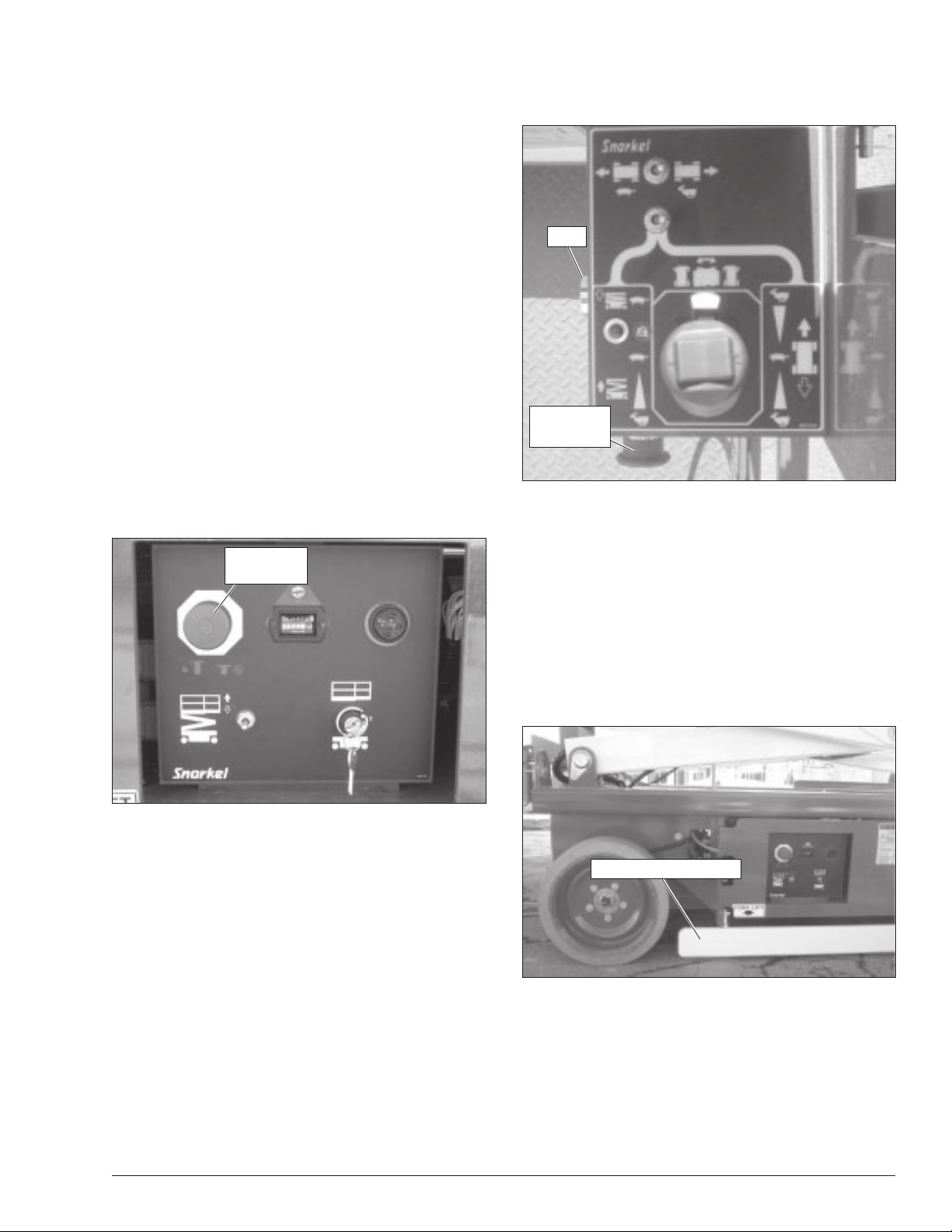
At the lower controls, the emergency stop is a two-posi-
tion push button (refer to Figure 4.1).
Figure 4.1 – Lower Controls
Push the emergency stop button in to disconnect power
to all control circuits. Pull the button out to restore power.
Note
The lower controls override the upper controls. If the up-
per control emergency stop button is engaged, the lower
controls can still be used to operate the aerial platform.
At the upper controls, the emergency stop is a two-posi-
tion push button (refer to Figure 4.2).
Push the emergency stop button in to disconnect power
to the upper control circuits. Pull the button out to re-
store power.
Figure 4.2 – Upper Controls
Drive Motion Alarm
When the joystick is moved out of neutral to drive the
aerial platform, the alarm emits a loud beeping sound to
warn personnel in the work area to stand clear .
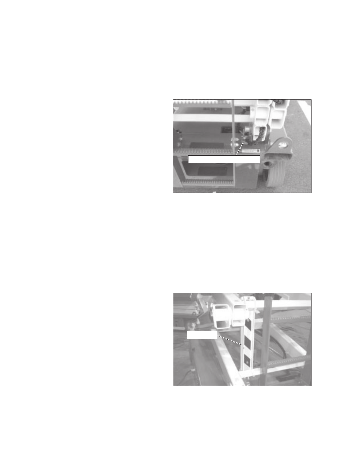
Pothole Protector Skids
The pothole protector skids automatically lower when the
platform is elevated approximately 61 cm (24″). Ground
clearance is reduced from 10.1 cm (4″) to 2.5 cm (1″)
when the skids lock into position (refer to Figure 4.3).
Figure 4.3 – Pothole Protector Skids
ADanger
The aerial platform can tip over if it becomes un-
stable. Death or serious injury will result from a tip-
over accident. Do not drive or position the aerial
platform for elevated use within 1.2 m (4
′′
′′
′) of any
drop-off, hole, or other tip-over hazard.
Pothole Protector Skid
Emergency
Stop Button
Emergency
Stop Button
Horn
Chapter 4 – Safety Devices
12 S2646/3246 – 0410063EE
Center the control in neutral to reset the lowering func-
tion, then continue to lower the platform.
Emergency Lowering Handle
The emergency lowering handle may be used to lower
the platform if there is a malfunction in the hydraulic or
electrical system. The handle is mounted at the rear of
the aerial platform (refer to Figure 4.4).
Figure 4.4 – Emergency Lowering Handle
The emergency lowering handle may be used to lower
the scissors arms onto the safety prop before inspecting
the machine. Pull the handle outward to lower the plat-
form. Push the handle all the way back in after lowering
the platform.
Safety Prop
The safety prop (refer to Figure 4.5) is used to support
the scissors structure when access to the scissors arm
components or the chassis is required. Always use the
safety prop when the platform is raised during inspection
and maintenance.
Figure 4.5 – Safety Prop
This protection system limits the tilt angle if a wheel is
driven into a drop-off or hole. This greatly reduces the
likelihood of the aerial platform tipping over .
The pothole protection system is for added protection
and does not justify operating near drop-offs or holes.
Drive/Lift Pothole Protector Interlock
The aerial platform drive and lift functions are interlocked
through a limit switch that senses whether or not the
pothole protection linkage is locked into position. The
drive/lift pothole interlock operates when the platform is
elevated approximately 2.1 to 2.4 m (7 to 8 feet).
If an obstruction under the skids, or some other impair-
ment prevents the skids from locking into position, the
drive and lift functions will not operate and an alarm will
sound.
Lower the platform and remove the obstruction when the
drive/lift pothole protector interlock alarm sounds.
Drive/Lift Level Sensor Interlock
The aerial platform drive and lift functions are interlocked
through a level sensor system. The drive/lift level sensor
interlock operates when the platform is elevated approxi-
mately 2.1 to 2.4 m (7 to 8 feet).
If the chassis is tilted more than two degrees side-to-
side or four degrees front-to-rear, the drive and lif t func-
tions will not operate and an alarm will sound.
Lower the platform and drive to a level surface when the
drive/lift level sensor alarm sounds.
The drive/lift level sensor system is for added protection
and does not justify operating on anything other than firm,
flat, level surfaces.
Lowering Alarm
When the joystick is moved out of neutral to lower the
platform, the alarm emits a loud beeping sound to warn
personnel in the work area to stand clear .
ADanger
Pinch points exist on the scissors structure. Death
or serious injury will result if the scissors structure
lowers onto personnel within the scissors arms or
under the raised platform. Stand clear while rais-
ing and lowering the platform.
Be careful when lowering the platform. Keep hands and
fingers away from the scissors structures components.
Lowering Interrupt
When the platform is lowered to about 1.5 m (5′) lowering
stops. The platform will not lower for five seconds regard-
less of the control position to allow personnel to clear the
area of the scissors before the platform completely low-
ers.
Safety Prop
Emergency Lowering Handle
Chapter 4 – Safety Devices
S2646/3246 – 0410063EE 13
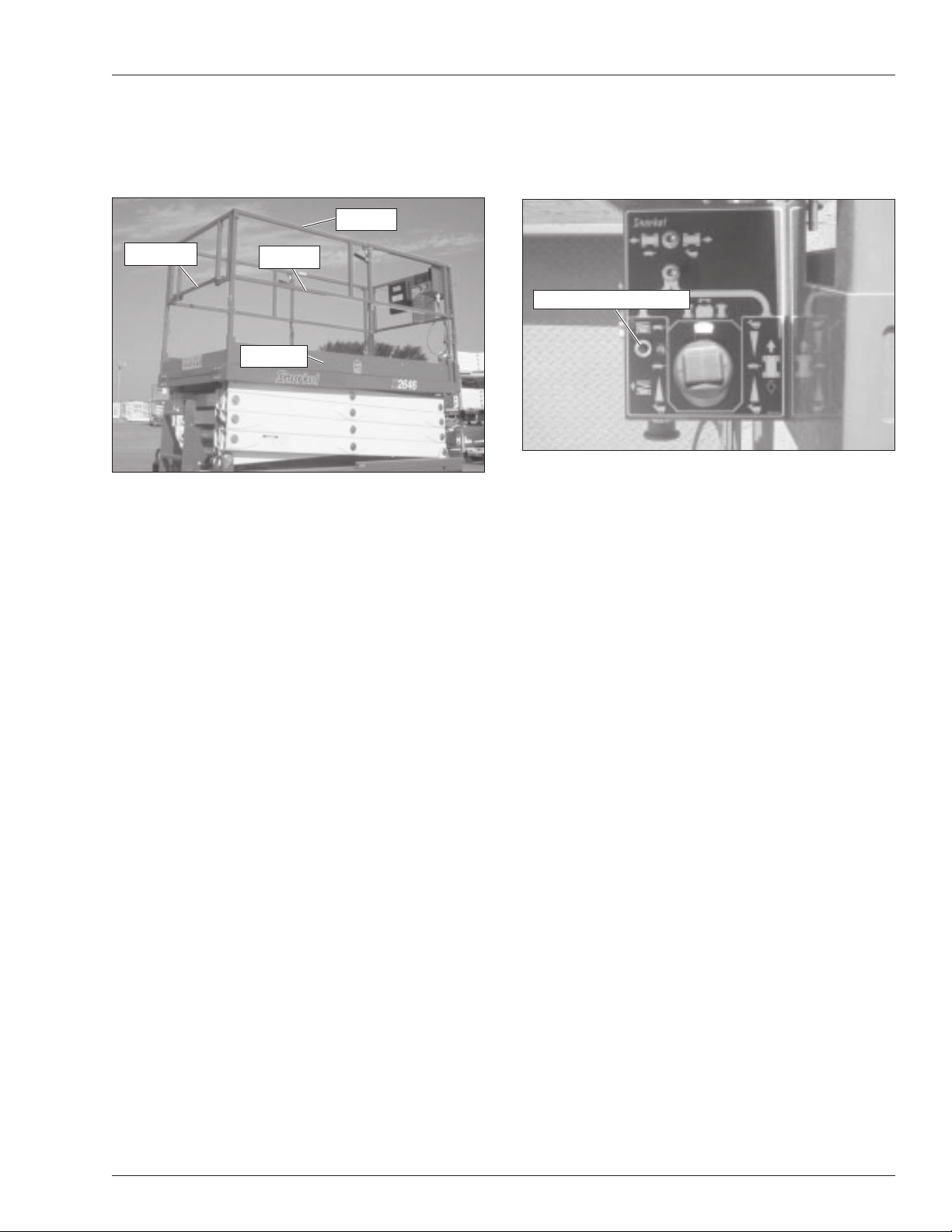
Guardrails
The guardrail system includes a top rail, mid rail, and
toeboards around the sides of the platform (refer to Fig-
ure 4.6).
Figure 4.6 – Platform
An entry gate allows for access to the platform for load-
ing work materials. The gate is part of the guardrail sys-
tem and must be securely fastened after loading and
entering the platform.
Horn
The horn may be used to warn personnel on the ground.
The horn is operational when the machine is set up for
operation from the upper controls.
Tilt Alarm
An alarm will sound if the aerial platform chassis is out of
level more than two degrees side-to-side or four degrees
front-to-rear when the platform is raised.
ADanger
The aerial platform can tip over if it becomes un-
stable. Death or serious injury will result from a tip-
over accident. Do not drive or position the aerial
platform for elevated use near any drop-off, hole,
slope, soft or uneven ground, or other tip-over haz-
ard.
Completely lower the platform and then drive to a level
surface when the tilt alarm sounds.
The tilt alarm is for added protection and does not justify
operating on anything other than firm, flat, level surfaces.
Overload Protection
When the load in the platform is near or at rated capac-
ity, an alarm will sound and the red light on the upper
controls (refer to Figure 4.7) will flash.
Figure 4.7 – Upper Controls
The alarm and light warn the operator that the platform is
close to becoming overloaded. All functions remain fully
operational.
ADanger
The aerial platform can tip over if it becomes un-
stable. Death or serious injury will result from a tip-
over accident. Do not exceed the capacity values
indicated on the platform rating placard.
If the platform is fully lowered and is overloaded, when it
is elevated just past 1.8 m (6′), a control module will stop
the lift and drive functions and the alarm will sound and
the warning light will flash. The platform can still be low-
ered to remove the excess load.
If the platform is elevated just past 1.8 m (6′) and material
is added to the platform overloading it, a control module
will stop the lift, drive and lower functions and the alarm
will sound and the warning light will flash. In this case,
remove the load in excess of rated capacity and cycle
the emergency stop button at the upper controls to re-
turn to normal operation.
Flashing Light
An optional red or amber flashing light may be located at
the rear of the aerial platform. The flashing light warns
personnel that the aerial platform is in the area.
The light flashes at about one flash per second when the
machine is set up for operation from the upper controls.
Toeboard
Top Rail
Mid Rail
Entry Gate
Overload Warning Light

Chapter 4 – Safety Devices
14 S2646/3246 – 0410063EE
 Loading...