


PARTS & SERVICE
Part number 514252-200 March 2014


 006001 +
SERVICE & PARTS
MANUAL
A38E
Aerial Work Platform
Nameplate
The Serial Number of the Work
Platform is also stamped on the inside of the Chassis, close to the
Steering Cylinder.
When contacting Snorkel for service or parts information, sure to include the MODEL and SERIAL NUMBERS from the equipment nameplate.
The A38E work platform meets and exceeds the requirements of both:
En280:2001 and ANSI A92.5 (1992)
A38E Work Platform |
i |
WARNING
All personnel shall carefully read, understand and follow all safety rules and operating instructions before operating or performing maintenance on any Snorkel aerial work platform.
Safety Rules
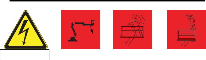
Electrocution Hazard |
Tip Over Hazard |
|
Collision Hazard |
Fall Hazard |
|||||
|
|
|
|
|
|
|
|
|
|
|
|
|
|
|
|
|
|
|
|
THIS MACHINE IS NOT
INSULATED!
8 3 B A
t h g i pR U
NEVER elevate the platform or drive |
NEVER position the platform |
the machine while elevated unless |
without first checking for overhead |
the machine is on a firm, level |
obstructions or other hazards. |
surface. |
|
NEVER climb, stand, or sit on platform guardrails or midrail.
USE OF THE AERIAL WORK PLATFORM: This aerial work platform is intended to lift persons and his tools as well as the material used for the job. It is designed for repair and assembly jobs and assignments at overhead workplaces (ceilings, cranes, roof structures, buildings etc.). All other uses of the aerial work platform are prohibited!
THIS AERIAL WORK PLATFORM IS NOT INSULATED! For this reason it is imperative to keep a safe distance from live parts of electrical equipment!
NEVER get closer than the minimum distance recommended by your National Regulations.
Exceeding the specified permissible maximum load is prohibited! See “Platform Capacity” for details. The use and operation of the aerial work platform as a lifting tool or a crane is prohibited!
NEVER exceed the manual force allowed for this machine. See “Manual Force” for details. DISTRIBUTE all platform loads evenly on the platform.
NEVER operate the machine without first surveying the work area for surface hazards such as holes, drop-offs, bumps, curbs, or debris; and avoiding them.
OPERATE machine only on surfaces capable of supporting wheel loads.
NEVER operate the machine when wind speeds exceed this machine’s wind rating. “Beaufort Scale” for details. IN CASE OF EMERGENCY push EMERGENCY STOP switch to deactivate all powered functions.
IF ALARM SOUNDS while platform is elevated, STOP, carefully lower platform. Move machine to a firm, level surface.
Climbing up the railing of the platform, standing on or stepping from the platform onto buildings, steel or prefab concrete structures, etc., is prohibited!
Dismantling the entry gate or other railing components is prohibited! Always make certain that the entry gate is closed and securely locked!
It is prohibited to keep the entry gate in an open position when the platform is raised!
To extend the height or the range by placing of ladders, scaffolds or similar devices on the platform is prohibited! NEVER perform service on machine while platform is elevated without blocking elevating assembly.
INSPECT the machine thoroughly for cracked welds, loose or missing hardware, hydraulic leaks, loose wire connections, and damaged cables or hoses before using.
VERIFY that all labels are in place and legible before using.
NEVER use a machine that is damaged, not functioning properly, or has damaged or missing labels.
To bypass any safety equipment is prohibited and presents a danger for the persons on the aerial work platform and in its working range.
NEVER charge batteries near sparks or open flame. Charging batteries emit explosive hydrogen gas. Modifications to the aerial work platform are prohibited or permissible only at the approval by Snorkel . AFTER USE, secure the work platform from unauthorized use by turning the keyswitch off and removing key. The driving of MEWP’s on the public highway is subject to regulations made under the Road Traffic Acts.
ALWAYS use a full body harness, prior to raising the platform, as recommended by the Health and Safety Executive (H1/05/05)
ii |
A38E Work Platform |
Safety Rules
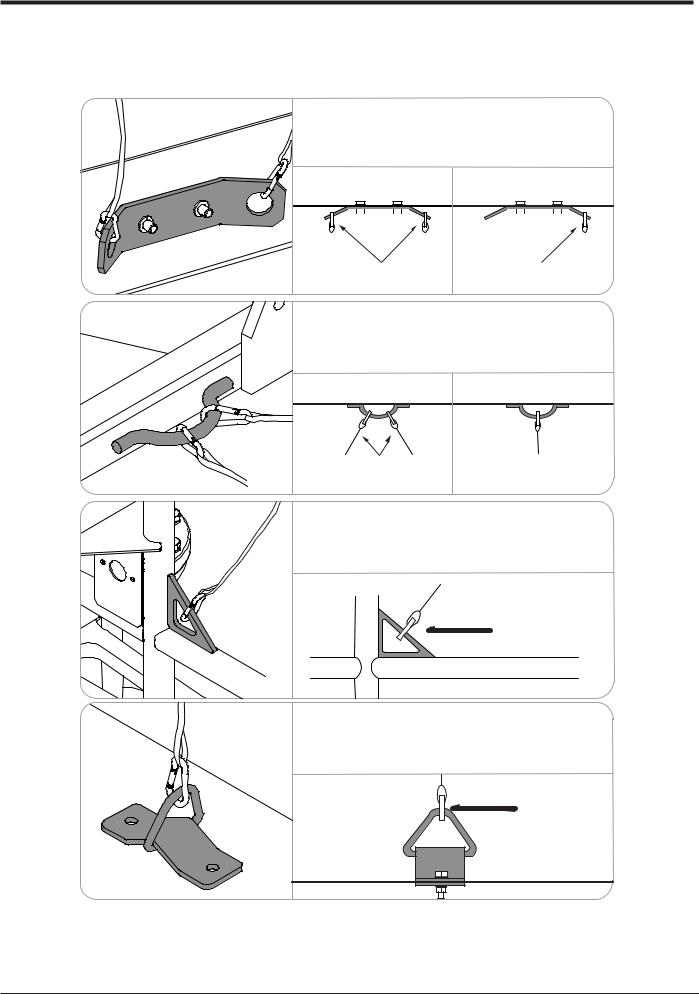
Harness attachment points are provided in the platform and the manufacturer recommends the usage of a fall restraint harness, especially where required by national safety regulations.
All harness attachment points on SNORKEL vehicles have been tested with a force of 3,650 lbs (16.3 KN) per person.
See below examples of harness attachment points used on SNORKEL vehicles with their corrosponding rating;
Harness attachment point Type 1. is rated for one lanyard attachment per loop as shown in the
 illustrations depending upon platform occupancy rating
 (see operators manual & decals).
Top View |
|
Top View |
|||||||||||
|
|
|
|
|
|
|
|
|
|
|
|
|
|
|
|
|
|
|
|
|
|
|
|
|
|
|
|
|
|
|
2 lanyard |
|
1 lanyard |
|
|
Type 1. |
|
attachments |
|
attachment |
|
|
|
|
|
|
|||||
|
|
Harness attachment point Type 2. is rated for two |
|||||
|
|
lanyard attachments per loop as shown in the |
|||||
|
|
illustrations depending upon platform occupancy rating |
|||||
|
|
(see operators manual & decals). |
|
|
|
||
|
|
|
Top View |
Top View |
|||
|
|
|
|||||
|
2 lanyard |
1 lanyard |
Type 2. |
attachments |
attachment |
|
|
|
|
Harness attachment point Type 3. is rated for one |
|
|
lanyard attachment per loop as shown in the |
|
|
illustrations depending upon platform occupancy rating |
|
|
(see operators manual & decals). |
|
|
Front View |
|
|
|
1 lanyard |
|
|
attachment |
Type 3. |
|
|
|
Harness attachment point Type 4. is rated for one |
|
|
lanyard attachment per loop as shown in the |
|
|
illustrations depending upon platform occupancy rating |
|
|
(see operators manual & decals). |
|
|
|
1 lanyard |
|
|
attachment |
Type 4.
NOTE: There can be more harness attachment points per machine than the maximum number of occupants allowed in a platform. Refer to
the platform decal & specifications table listed in the operators manual for the correct occupancy rating before use.
A38E Work Platform |
iii |
NOTES:
iv |
A38E Work Platform |

Foreword
Introduction
HOW TO USE THIS MANUAL
This manual is divided into 7 Sections,
The right hand pages of each Section is marked with a black
section number printed at the top corner of each page which can be used as a quick guide.
SPECIAL INFORMATION
D A N G E R
Indicates an imminently hazardous situation which, if not avoided, will result in severe injury or death.
W A R N I N G
Indicates a potentially hazardous situation which, if not avoided, could result in severe injury or death.
C A U T I O N
Indicates a potentially hazardous sit uation which, if not avoided, may result in minor or moderate injury.
WORKSHOP PROCEDURES
C A U T I O N
Detailed descriptions of standard workshop procedures, safety principles and service operations
are not included. Please note that this manual does contain warnings and cautions against some specific
service methods which could cause personal injury, or could damage a machine and make it unsafe. Please understand that these warnings cannot cover
all conceivable ways in which service, whether or not
recommended by Snorkel, can be done, or the possible hazardous consequences of each conceivable way,
nor could Snorkel investigate all ways. Anyone using service procedures or tools, whether or not recom-
mended by Snorkel, must satisfy themselves thoroughly that neither personal safety nor machine
safety will be jeopardised.
Notes: Give helpful information.
All information contained in this manual is based on the latest product information available at the time of printing. We reserve the right to make changes at any time without notice. No part of this publication may be reproduced, stored in retrieval system, or transmitted, in any form by any means, electronic, mechanical, photocopying, recording, or otherwise, without prior written permission of the publisher. This includes text, figures and tables.
A38E Work Platform

Foreword
NOTES:
vi |
A38E Work Platform |

Contents
Section
i
Table of Contents
Section |
Page |
No. |
No. |
1.0Introduction & Specifications
1.0 |
Introduction ........................................................ |
1-1 |
|
Purpose .......................................................... |
1-1 |
|
Scope .............................................................. |
1-1 |
1.1 |
General Information .......................................... |
1-1 |
|
Platform .......................................................... |
1-1 |
|
Control Box .................................................... |
1-1 |
|
Elevating Assembly ..................................... |
1-1 |
|
Rotation Gear ................................................ |
1-1 |
|
Drive & Steer Systems ................................. |
1-2 |
|
Power System ................................................ |
1-2 |
|
Control System ............................................. |
1-2 |
|
Chassis ........................................................... |
1-2 |
|
A38E Purpose & Limitations ...................... |
1-2 |
1.2 |
Specifications ..................................................... |
1-3 |
1.3 |
Notes ..................................................................... |
1-4 |
2.0Machine Preparation
2.1 |
Preparation For Use ......................................... |
2-1 |
2.2 |
Preparation For Shipment ............................... |
2-1 |
2.3 |
Forklifting The Work Platform ........................ |
2-1 |
2.4 |
Lifting The Work Platform ................................ |
2-1 |
2.5 |
Transport by Truck ............................................. |
2-1 |
2.6 |
Manual Brake Release ...................................... |
2-2 |
2.7 |
Storage ................................................................. |
2-2 |
2.8 |
Notes ..................................................................... |
2-3 |
3.0Operation
3.0 |
Introduction ........................................................ |
3-1 |
|
General Functioning ..................................... |
3-1 |
|
Driving ........................................................... |
3-1 |
|
Steering .......................................................... |
3-1 |
|
Operating the Booms ................................... |
3-1 |
|
Design Features ............................................ |
3-2 |
3.1 |
Safety Rules & Precautions ............................. |
3-3 |
3.2 |
Controls & Indicators ....................................... |
3-4 |
3.3 |
Pre-Operation Inspection ................................. |
3-6 |
|
System Function Inspection ....................... |
3-6 |
3.4 |
Opertaion ............................................................ |
3-7 |
|
Elevating & Lowering The |
|
|
A38E Work Platform ................................. |
3-7 |
|
Travel With The Work Platform |
|
|
Lowered ..................................................... |
3-7 |
|
Travel With The Work Platform |
|
|
Elevated ..................................................... |
3-8 |
|
Levelling ........................................................ |
3-8 |
|
Emergency Situations & |
|
|
Emergency Override ................................. |
3-8 |
|
Emergency Lowering ...................... |
3-8 |
|
Control From Ground Level ........................ |
3-9 |
|
After Use Each Day ..................................... |
3-9 |
|
Manual Rotation ........................................... |
3-9 |
|
Manual Telescopic Retraction .................... |
3-9 |
3.5 |
Notes ..................................................................... |
3-11 |
Section |
Page |
No. |
No. |
4.0Maintenance
4.0 |
Introduction ........................................................ |
4-1 |
|
Tools Required .............................................. |
4-1 |
4.1 |
Preventative Maintenance ............................... |
4-1 |
|
Preventative Maintenance |
|
|
Table Key .................................................... |
4-2 |
|
Preventative Maintenance |
|
|
Report .......................................................... |
4-2 |
4.2 |
Battery Maintenance ......................................... |
4-3 |
|
Battery Inspection & Cleaning ................... |
4-3 |
|
Battery Charging .......................................... |
4-3 |
|
Battery Cell Equalization ............................. |
4-4 |
4.3Temperature Correction For
|
Electrolyte Readings ...................................... |
4-4 |
4.4 |
Lubrication ......................................................... |
4-5 |
|
Grease Fittings .............................................. |
4-5 |
|
Slew Ring ....................................................... |
4-5 |
|
Pivot Pins ....................................................... |
4-5 |
|
Hydraulic Oil Tank & Filter ......................... |
4-5 |
4.5 |
Setting Hydraulic Pressures ............................ |
4-6 |
|
Main Relief Valve .......................................... |
4-6 |
|
Slew Cross-Line Relief Valve ...................... |
4-7 |
4.6 |
Maintenance on Elevating Assembly ............. |
4-7 |
|
Installation of Elevating Assembly |
4-7 |
|
Support ....................................................... |
|
|
Removal of Elevating Assembly |
|
|
Support ....................................................... |
4-7 |
4.7 |
Switch Adjustments ............................................ |
4-8 |
|
Tilt Sensor ..................................................... |
4-8 |
|
Boom Rest Limit Switch ... ........................... |
4-8 |
4.8 |
Hydraulic Manifold ........................................... |
4-10 |
|
Removal ......................................................... |
4-10 |
|
Disassembly .................................................. |
4-10 |
|
Cleaning & Inspection ................................. |
4-10 |
|
Assembly ....................................................... |
4-10 |
|
Installation ..................................................... |
4-10 |
4.9 |
Hydraulic Pump ................................................. |
4-12 |
|
Removal ......................................................... |
4-12 |
|
Installation ..................................................... |
4-12 |
4.10 |
Traction Motor Maintenance .......................... |
4-12 |
|
Inspecting the Drive Motor ........................ |
4-12 |
4.11 |
Electric Motor .................................................... |
4-14 |
|
Troubleshooting ........................................... |
4-14 |
|
Disassembley ................................................ |
4-14 |
|
Inspection ...................................................... |
4-14 |
|
Reassembley ................................................. |
4-14 |
|
Maintenance Intervals & Procedures ....... |
4-15 |
4.12 |
Drive Reduction Gearbox ................................. |
4-17 |
|
Changing the Oil ........................................... |
4-18 |
4.13 |
Torque Specifications ........................................ |
4-18 |
4.14 |
Lower Lift Cylinder ............................................ |
4-19 |
|
Removal ......................................................... |
4-19 |
|
Disassembly .................................................. |
4-19 |
|
Cleaning & Inspection ................................. |
4-19 |
|
Reassembly/Seal Replacement ................... |
4-20 |
A38E Work Platform |
I |

Section
i
Contents
Table of Contents
Section |
|
Page |
No. |
|
No. |
|
Installation ..................................................... |
4-20 |
4.15 |
Upper Lift Cylinder ............................................ |
4-21 |
|
Removal ......................................................... |
4-21 |
|
Disassembly .................................................. |
4-21 |
|
Cleaning & Inspection ................................. |
4-21 |
|
Reassembly/Seal Replacement ................... |
4-21 |
|
Installation ..................................................... |
4-22 |
4.16 |
Telescopic Cylinder ........................................... |
4-22 |
|
Removal ......................................................... |
4-22 |
|
Disassembly .................................................. |
4-23 |
|
Cleaning & Inspection ................................. |
4-23 |
|
Reassembly/Seal Replacement ................... |
4-23 |
|
Installation ..................................................... |
4-23 |
4.17 |
Steering Cylinder ............................................... |
4-23 |
|
Removal ......................................................... |
4-23 |
|
Disassembly .................................................. |
4-23 |
|
Cleaning & Inspection ................................. |
4-24 |
|
Reassembly/Seal Replacement ................... |
4-24 |
|
Installation ..................................................... |
4-24 |
4.18 |
Master Levelling Cylinder ............................... |
4-25 |
|
Removal ......................................................... |
4-25 |
|
Disassembly .................................................. |
4-25 |
|
Cleaning & Inspection ................................. |
4-25 |
|
Reassembly/Seal Replacement ................... |
4-25 |
|
Installation ..................................................... |
4-25 |
4.19 |
Slave Levelling Cylinder .................................. |
4-26 |
|
Removal ......................................................... |
4-26 |
|
Disassembly .................................................. |
4-26 |
|
Cleaning & Inspection ................................. |
4-26 |
|
Reassembly/Seal Replacement ................... |
4-26 |
|
Installation ..................................................... |
4-27 |
|
Bleeding the Master/Slave |
|
|
Levelling Circuit ........................................ |
4-27 |
4.20 Adjustment Of Overcentre Valves .................... |
4-28 |
|
4.21 Replacing GP400 control module .................... |
4-29 |
|
4.22 Calibration of load cell ................................... |
4-30 |
|
5.0Troubleshooting
5.0 |
Introduction ........................................................ |
5-1 |
|
General Procedure ........................................ |
5-1 |
|
Special Tools ................................................ |
5-2 |
|
Adjustment Procedures .......... ..................... |
5-2 |
|
Checking Pump Preasure............................... |
5-2 |
|
Diagnostics using Ezcal display................... |
5-2 |
5.1 |
I/O Matrix ..................................................... |
5-3 |
Troubleshooting Guides ....... .................... |
5-4 |
|
5.2 |
Replacing the GP400 Control module ....... |
5-6 |
|
GP400 I/O Allocations............................... |
5-7 |
|
Notes ........................................................ |
5-8 |
6.0Schematics
6.0 |
Introduction ........................................................ |
6-1 |
6.1 |
Electrical Schematics ........................................ |
6-3 |
6.2 |
Hydraulic Schematics ....................................... |
6-6 |
Section |
Page |
No. |
No. |
7.0Illustrated Parts Breakdown
7.0 |
Introduction ........................................................ |
7-1 |
7.1 |
Index ..................................................................... |
7-1 |
7.2 |
Illustrated Parts Breakdown .......................... |
7-2 |
Final Assembly A38E ................. ................................ |
7-2 |
Chassis Assembly .......................................................... |
7-4 |
A38 PG Parts Assembly ................................ ............... |
7-6 |
Booms and Posts Assembly ........................... ............... |
7-8 |
Cage and Cradle Assembly.................................................... |
7-10 |
Cage and Cradle Assembly (Rotator) ................................... |
7-12 |
Wheel Hub Assembly .......................................................... |
7-14 |
Drive Reduction Gear box Assembly .................................. |
7-16 |
Traction Motor Assembly (514274-000)............................. |
7-18 |
Traction Motor Assembly (512944-000)............................. |
7-20 |
Motor / Pump Assembly.................................................. |
7-22 |
Re ar & Front Wheel Kit ................................................. |
7-24 |
Worm Drive Unit & Slew Bearing....................................... |
7-26 |
Manifold Block Assembly ............................................... |
7-28 |
Lower Lift Cylinde r Assembly............................................. |
7-30 |
Upper Lift Cylinder Assembly ............................................ |
7-32 |
Telescopic Cylinder Assembly............................................. |
7-34 |
Steeri ng Cylinder Assembly................................................ |
7-36 |
Master / Slave Cylinder Assembly...................................... |
7-38 |
Lower Control Box Assembly ............................................ |
7-40 |
Upper Control Box Assembly (CE)..................................... |
7-42 |
Upper Control Box Assembly (ANSI)................................. |
7-44 |
Cables & Electrical Components.......................................... |
7-46 |
Hose Assembly................................................................... |
7-48 |
Decal Kit - ANSI Version ............................................... |
7-50 |
Decal Kit - CE Version .................................................... |
7-52 |
Options List .......................................................................... |
7-54 |
II |
A38E Work Platform |
Contents
NOTES:
Section
i
A38E Work Platform |
III |

Section
i
Contents
NOTES:
IV |
A38E Work Platform |

Introduction & Specifications
Section
1.0
1.0 Introduction
PURPOSE
The purpose of this Service & Parts Manual is to
provide instructions and illustrations for the operation and maintenance of the A38E Work Platform
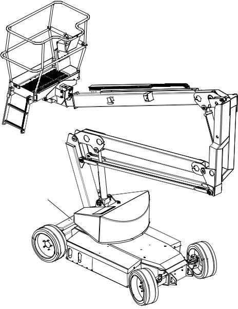
manufactured by Snorkel. (See Figure 1-1).
SCOPE
The manual includes the procedures and
responsibilities which must be strictly adhered to for proper operation, maintenance, adjustment, and
repair of this product. The Maintenance Section
further covers preventative maintenance and trouble shooting.
1.1 General Information
The A38E is a quickly deployable self propelled aerial work platform, designed to raise a specified number of operators with hand tools to a work height of up
to 13.45 m (44.12ft.) i.e. a platform floor height of 11.45 m (37.56 ft.). It is designed to provide mobility with the Platform in the raised or lowered position, although travel with the Platform raised is limited to a low speed. The boom assembly and telescope functions are operated by a hydraulic pump driven by a DC electric motor. Two DC electric traction motors coupled to two braked gearboxes regulate the drive function.
PLATFORM
The platform is large enough for a specified number of operators and has a free-draining perforated floor with 150 mm (5.9inches) toe boards. Hand rails are constructed from steel tubing and a safety drop-bar is
provided at the entrance. Safety harness anchor points are also fitted in the floor of the platform. The primary Control Box is fitted permanently within this platform.
 W A R N I N G
DO NOT begin using the machine until the platform entrance drop bar is in the fully lowered position.
CONTROL BOX
The control box is permanently fitted at the front
centre of the platform. It features a Joystick which will provide proportional control for raising or
lowering either of the two booms, extending or retracting the Telescopic Boom, rotating (slewing)
the entire Booms & Posts Assembly or driving.
A safety feature which is incorporated into the Joystick’s operation is the Interlock Switch. This
must be activated at all times while operation is required. This allows for one-handed operation. A
complete explanation of control functions can be found in Section 3.
ELEVATING ASSEMBLY
The platform is raised and lowered by a combination
of two steel lift booms and one telescopic boom, each of which is operated by a hydraulic cylinder
which in turn is actuated by hydraulic power from the
motor driven pump. Solenoid operated valves control to which cylinder the hydraulic oil is directed. Each
cylinder features an integral holding valve to prevent uncontrolled descent in the case of a hose burst.
ROTATION GEAR
The Booms & Posts Assembly can be rotated to
provide up to 5.6 m (18.4 ft.) of side outreach, measured from the centreline of rotation to the front
of the Platform. This is done by means of an integral hydraulic motor driving a Worm Drive Unit, around a
large diameter Slew Gear.
|
1. |
|
6. |
|
|
2. |
|
|
|
|
|
|
7. |
|
|
|
|
|
5. |
1. |
Platform |
|
|
2. |
Elevating Assembly |
|
|
3. |
Chassis |
4. |
3. |
4. |
Power Module |
||
5. |
Control Module |
|
|
6. |
Platform Control Box |
|
|
7. |
Lower Control Box |
|
|
|
Figure 1-1: A38E Work Platform |
||
A38E Work Platform |
1-1 |

Section
1.1
Introduction & Specifications
DRIVE & STEER SYSTEMS
The A38E Work Platform is restricted to low speed
drive when the Platform is raised above the Boom Rest Limit Switch. The Traction controller controls the
application of drive from the Joystick by means of two Traction Motors, which are assembled to the drive
wheels via a Drive Reduction Gearbox.
Steering of the A38E Work Platform is controlled by a double acting cylinder. An Operator can Steer left or right by depressing the Rocker Switches on top of the Joystick, while activating the Interlock Switch.
POWER SYSTEM
The power system incorporates eight 6V batteries
driving the drive traction motors, or the 4kW (5.4HP) electric motor which in turn drives the hydraulic
pump. The application of this hydraulic pressure is performed by the Control System.
CONTROL SYSTEM
The machine is provided with fully proportional controls by means of the interaction between a
P600, electronic motor controller and a proportional
joystick. The P600 and motor controller regulate the drive motor/pump speed and hence the flow of oil
reaching the cylinders, the Worm Drive Unit or the Drive Reduction Gearbox. It regulates the direction of
flow of the hydraulic oil via the solenoid valves located
on the manifold block, and it also monitors the operation of all switches on the machine via the machine
harness system.
The motor control units are located, in the left hand chassis module. The manifold block is located on the
hydraulic tank. This is accessible by removing the main cover.
CHASSIS
The chassis is a structural frame designed to support all the components of the A38E Work Platform.
1-2
A38E PURPOSE & LIMITATIONS
The purpose of the A38E work platform is to provide a quickly deployable variable height work platform. It is capable of lifting a specified number of people with work tools up to an upper limit of 215 kg (ANSI 475 lbs) in total. The unit will provide the ability to reach over obstacles but must be used on firm level ground.
See Specification table on page 1-3.
The platform must only be used on firm level or slightly uneven ground capable of supporting the maximum load generated under the four wheels. Do not use on soft or severely sloping ground.
DANGER
NOTE: It should be recognised that if the tilt switch senses a degree of slope greater than 3º the elevating circuits will lockout and sound a warning alarm. The Emergency Override should then be used, to lower the Elevating Assembly.
A38E Work Platform

Introduction & Specifications
Section
1.2
1.2 Specifications
Table 1-1: Specifications
ITEM |
METRIC |
IMPERIAL (ANSI) |
|
Duty Cycle |
45% of 8 hour shift |
45% of 8 hour shift |
|
Platform Size |
0.58 m x 1.3 m (inside gaurdrails) |
1.77 ft x 4.3 ft (inside gaurdrails) |
|
Max. Platform Capacity |
215 kg |
475 lbs |
|
Indoors |
2 People |
2 People |
|
Outdoors |
1 People |
2 People |
|
Maximum Working Height |
13.45 m |
44.12 ft |
|
Maximum Platform Height |
11.45 m |
37.56 ft |
|
Min. Platform Floor Height |
0.65 m |
2.13ft |
|
Max. Working Outreach |
6.10 m |
20.00 ft |
|
Platform Height At |
5.40 m |
17.72 ft |
|
Maximum Outreach |
|||
|
|
||
Stowed Dimensions |
|
|
|
Length |
4.04 m |
13.25 ft |
|
Width |
1.50 m |
4.92 ft |
|
Height |
2.00 m |
6.56 ft |
|
Ground Clearance |
0.12 m |
0.39 ft |
|
|
|
|
|
Wheel Base x Gauge |
2.00 m x 1.27 m |
6.56 ft x 4.16 ft |
|
Rotation |
362 degrees non-continuous |
362 degrees non-continuous |
|
Unloaded Weight |
3,770 kg |
7,826 lbs |
|
With Load/ Max Weight |
3,985kg |
8,840 lbs |
|
Drive Speed Stowed |
0 - 4 km/h |
0 - 2.49 mph |
|
Drive Speed Elevated |
0 - 0.4 km/h |
0 - 0.25 mph |
|
Maximum Gradeability |
36% |
36% |
|
|
|
|
|
Inside Turning Radius |
0.40 m |
1.31 ft |
|
Outside Turning Radius |
2.40 m |
7.87 ft |
|
Power Source |
48V DC 4kW, 8 X 6V 210Ah Batteries |
48V DC 5.4HP, 8 X 6V 210Ah Batteries |
|
System Voltage Control |
12V |
12V |
|
Battery Charger |
Auto Dual AC input 100-240V ~ 50/60Hz 18A |
Auto Dual AC input 100-240V ~ 50/60Hz 18A |
|
|
Output 48V, 25A |
Output 48V, 25A |
|
Hydraulic Oil Tank Capacity |
25 Litres |
6.5 Gallons US |
|
Max. Hydraulic Pressure |
145 bar |
2105 psi |
|
Hydraulic Oil Grade |
ISO #46 |
ISO #46 |
|
Cylinder Types |
2 Double Acting Lift Cylinders With |
2 Double Acting Lift Cylinders With |
|
Lock Valves And Manual Emergency |
Lock Valves And Manual Emergency |
||
|
Lowering Facility. |
Lowering Facility. |
|
|
1 Double ActingTelescopic Cylinder |
1 Double ActingTelescopic Cylinder |
|
|
Refer to Section 5 of the Service & |
Refer to Section 5 of the Service & |
|
|
Parts Manual |
Parts Manual |
|
Control System |
One handed Proportional Joystick |
One handed Proportional Joystick |
|
Operating Energy Efficient Motor |
Operating Energy Efficient Motor |
||
|
Control System |
Control System |
|
Wheels/Tyres |
400 mm Diameter Steel Disc Wheel |
15.75 inch Diameter Steel Disc Wheel |
|
With Solid All Surface Tyres |
With Solid All Surface Tyres |
||
|
|||
Braking |
Automatic Spring Applied |
Automatic Spring Applied |
|
Hydraulic Release |
Hydraulic Release |
||
|
|||
Max Noise Level |
69.5 dB(A) |
69.5 dB(A) |
|
|
|
|
A38E Work Platform |
1-3 |

Section
1.3
Introduction & Specifications
NOTES:
1-4 |
A38E Work Platform |
Machine Preparation
Section
2.1
2.1 Preparation for use
CAUTION
Read, understand and follow all operating instructions before attempting to operate the machine.
2.2 Preparation for Shipment
1.Lubricate machine per lubrication instructions in Section 4.4, Maintenance.
2.Fully lower the platform and make sure the machine is stowed securely.
3.Check that the hydraulic oil level is adequate
and that it is not over filled.
Check that the batteries are charged and disconnect
the batteries using the Battery Disconnect Plug. This prevents excessive power drain prior to next
using the machine.
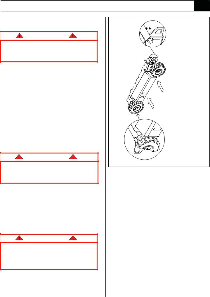
2.3 Forklifting the Work Platform
CAUTION
The A38E is not designed to be consistently forklifted. This operation can be used for very short distances only.
Forklift from the side by lifting under the chassis modules as per Figure 2-1. When lifting the A38E
with a forklift, great care should be taken not to damage the right or left hand modules as these
contain sensitive equipment.
2.4 Lifting the Work Platform
CAUTION
See specifications (Section 1.2) for the weight of the work platform and be certain that lifting apparatus is of adequate capacity to lift the platform.
The A38E may be lifted by an overhead hoist/crane in the following manner:
Four lifting straps capable of safely supporting the total weight of the A38E ( (3,770 Kg /7,430 lbs CE
Front Lifting / Tie-down Lug |
FORKLIFT HERE |
Rear Lifting / Tie-down Lug |
Figure 2-1: Forklifting & Lifting the A38E
Version & 4,010 Kg /8,840 lbs ANSI Version) and at
least 250 cm (8 ft.) long are required. This minimum length is important to ensure the correct lifting angle.
The straps should be positioned at the Lifting/Tie
Down Lugs as shown in Figure 2-1. Great care must be taken to avoid damage to any of the components
of the machine.
2.5 Transport by Truck
The A38E is normally carried upon a suitably rated transportation vehicle. Because of the high
gradeability of the A38E it will be capable of driving directly on to most vehicles. If however the loading
slope is greater than the gradeability or the batteries have been depleted sufficiently a winch should be
used. The procedure when using a winch is to
disengage the gearbox from the drive wheels using the Allen key release, and then winch the machine on
to the vehicle in its freewheel state.
Refer to Section 2.6 which follows.
A38E Work Platform |
2-1 |

Section
2.6
Machine Preparation
When the A38E is on the Truck it should then be made secure.
1.Chock the wheels of the A38E.
2.Secure the work platform to the transport
vehicle with chains or straps of adequate load capacity attached to the lifting lugs on the chassis.
CAUTION
Overtightening of the chains or straps through tiedown lugs may result in damage to the Work Platform.
2.6 Manual Brake Release
CAUTION
Perform this operation only when the machine will not operate under its own power and it is necessary to move the machine, or for winching onto a trailer for transportation. Ensure the machine is on level ground before commencing this operation and use wheel chocks as appropriate to prevent the machine from rolling inadvertently.
Do not exceed 3 mph. Faster speeds will damage drive components and void warranty.
1.Ensure that the Platform is fully lowered and
that the Elevating Assembly is slewed (rotated) such that the platform is stowed above the drive wheels. Turn the Upper Control Box to the OFF position and remove the key.
2.Attach a chain/cable of sufficient capacity for
towing the machine to the front or rear lifting/tie down lugs. Take up the slack in the chain/cable.
3.Locate the Allen head socket screws located in the centre of the two drive (rear) wheels and using a 6 mm Allen key, turn each one
clockwise to its full extent. The machine is now in freewheel mode.
WARNING
DO NOT leave the machine unattended or attempt to operate the A38E Work Platform until the Brake Release Screws have been re-engaged.
4.When towing is completed, turn both Allen head socket screws in a counter clockwise direction until they rest firmly against the locking circlip.
Figure 2-2 : Manual Brake Release
2.7 Storage
No preparation is required for storage when the Work Platform is in regular use. Regular maintenance per
Table 4-1 should be performed.
If the work platform is to be placed in long term storage (dead storage) use the following preservation procedure.
PRESERVATION
1.Clean painted surfaces. If the painted surface is damaged, repaint.
2.Fill the hydraulic tank to operating level with the platform fully lowered. Fluid should be visible
on the Dip Stick. It is not recommended that the hydraulic fluid be drained.
3.Coat exposed portions of cylinder rods with a
preservative such as multipurpose grease and wrap with barrier material.
4.Coat all exposed unpainted metal surfaces with preservative.
BATTERIES
1.Disconnect the batteries.
2.Disconnect the battery leads and secure to the chassis.
WARNING
Care should be taken, while disconnecting the
battery leads, that a short circuit does not occur. i.e. grounding to the chassis with a spanner.
3.Remove the batteries and place in alternate
service. Battery efficiencies are best realised when used consistently.
2-2 |
A38E Work Platform |

Machine Preparation
NOTES:
Section
2.7
A38E Work Platform |
2-3 |

Section
2.7
Machine Preparation
NOTES:
2-4 |
A38E Work Platform |
Operation
Section
3.0
3.0 Introduction
GENERAL FUNCTIONING
WARNING
Before beginning to operate the machine it is a mandatory requirement to read, fully understand and follow the Operators Manual.
The A38E Lift and Steer functions are operated by utilising a battery powered electric motor which drives a hydraulic pump. The pump supplies oil under pressure to the various platform functions.
electrically activated solenoid valves (the control of which solenoid valve activates and the rate at
electrical circuit, and its components).
The Drive function is operated by utilising two drive motors which are controlled by a Electronic Traction Motor Controller.
NOTE:
An Interlock Trigger Switch is an integral part of the Joystick. This must be depressed for the functions to operate. This will energise the Line Contactor and enable electrical control. (This safety feature prevents inadvertent activation of all powered functions, in the case of accidental movement of the Joystick.)
DRIVING
Platform controls provide variable speeds for the drive function through the use of a Joystick. This is
achieved using a motor control unit which varies the speed of the two DC electric traction motors. To drive
the A38E there are a number of steps which need be
taken. First the operator should ensure that neither of the Emergency Stop Buttons are pressed, then the
Keyswitch on the ground control panel should be
turned to the ‘PLATFORM CONTROL’ position.
Momentarily operate the drivefunction switch and
the A38E will be able to drive.
The machine will then drive at a speed proportional to the angle of the Joystick from the neutral (centre)
position, while the Joystick Interlock Switch is depressed. The speed range within which the machine will drive is deter-mined by whether or not the booms are raised.
If a boom is raised off the Boom Rest Limit Switch the current to the drive motors will be reduced leading to a significantly slower drive speed. This is a safety feature. The drive wheels are driven by two DC electric traction motors coupled to two braked gearboxes. When the Joystick is in the neutral position the brake chamber is free of oil and the internal spring within the gearbox maintains the braking pressure. Upon moving the Joystick the brake chambers will receive a flow of pressurised
oil which will release the brakes.
STEERING
Platform controls also provide a steering function through the use of ‘Rocker’ activated Steering
Switches in the Joystick. This is achieved by using the P600 which varies the hydraulic flow by altering
the voltage to the pump. To steer the A38E there are
a number of steps which need be taken.
First the operator should ensure that neither of the Emergency Stop Buttons are pressed, then the
Keyswitch ground control Panel should be turned to the ‘PLATFORM CONTROL’ position.
Momentarily operate the drive function switch to drive and the A38E will also be able to steer. To steer the machine the Rocker should be pushed to the left or the right, while the Joystick Interlock Switch is depressed. Steering left or right will energise the steering coils and allow oil to enter the full bore side or annular side of the steering cylinder, there by turning the wheels in the chosen direction. The orientation of the Platform to the Chassis will determine the direction the machine will travel when the Joystick is engaged.
NOTE:
Steering is not self-centring. The wheels must be returned to the straight ahead position by operating the Steering Switch.
OPERATING THE BOOMS
Boom functions, including the telescopic and slewing functions, can be operated either from the Platform
Controls or the Chassis Controls.
The Platform controls provide variable speeds for the
boom functions through the use of a Joystick. This is achieved using an P600 which varies the speed
of the motor/pump unit and increases or decreases
the flow of oil to the different functions. This control unit receives a control signal from the Joystick on the
upper controls, the speed of the motor will increase as the Joystick is pushed further away from the
neutral (centre) position.
A38E Work Platform |
3-1 |

Section
3.0
Operation
It will be noticed that on the Upper Control Box a set of switches are used to alternate functions. Each
function will have it’s corresponding graphicand lamp. This selector switch indicates to the Controller which
function is required and by using the Joystick the speed of this selected function can be adjusted.
The boom functions on the chassis controls provide proportional control for each function by way of an
analog rocker switch, the desired function can be
activated by holding on one of four switches on the controls and and operating the analog rocker, the
the four switchs act as both selector & enable switches.
The use of these functions is further explained throughout this Section.
DESIGN FEATURES
The A38E Series Work Platform has the following features:
The drive speed is limited to a ‘creep speed’ when operating the Work Platform while the machine is elevated.
The energy-efficient motor control units provides long battery life and smooth proportional control of the boom and drive functions.
All cylinders are fitted with hydraulic hose-burst protection interlocks.
The on-board charger is fully automatic and charges the batteries efficiently and economically. If the work platform starts to become unstable and
the Tilt Sensor is activated an alarm will sound in the upper control box. In this situation power is
partially cut to the upper controls to prevent any boom movements (i.e. UP, TELE OUT) that might
increase instability. An emergency override switch
is fitted to allow the booms to be lowered at a controlled speed to bring the machine back to a
stable position.
In the event of a power loss the two Boom Lift
Cylinders are fitted with emergency lowering valves which allow the booms to be lowered at a
controlled speed by an operator on the ground.
A Master Cylinder/Slave Cylinder levelling system ensures that the Platform remains level throughout the entire working cycle of the machine.
A manual rotation facility is fitted to allow rotation of the Elevating Assembly in the event of power loss.
HOUR METER & BATTERY CHARGE INDICATOR.
The A38E Series Work Platform is equiped with a display in the chassis control panel which displays total hours run & an Indication of remaining battery charge.
LOAD SENSI NG
The A38E is fitted with a load sensing system designed to comply with the requirements of :
BS EN 280 : 2001
If a load equivelent to 99% of safe working load is lifted an overload lamp will illuminate on the platform
control box.
If a load which is greater than the safe working load by
10% is present in the basket all machine functions will cease to operateand an acoustic warning will sound.
In order to returnto normal operation a load equal to or less than the safe working load must be present in the
basket andthe power must be re-cycled, power can be re-cycled by pushing the emergency stop button and releasing it again.
3-2 |
A38E Work Platform |

Operation
Section
3.1
3.1 Safety Rules and Precautions
WARNING
Before using the A38E Work Platform it is imperative to read, understand and follow the following Safety Rules and Precautions.
NEVER operate the machine unless you have been
fully trained in its safe use, are medically fit and have read and fully understood these instructions.
NEVER leave the A38E unattended with the Platform in the raised position.
ALWAYS position the machine on firm level ground
with a minimum bearing capacity of 78 kg /cm2 (1109 psi).
CHECK that no overhead obstructions exist within the machines range of movement.
DO NOT work within 3 metres (10 feet) of live overhead cables. Set up warning tape barrier at the
safe distance.
(THIS MACHINE IS NOT INSULATED).
DO NOT exceed the safe working load of 215 kg, (ANSI 475 lbs)
CE=max. 1 persons Outdoor + Tools 135Kg 2 person Indoor + Tools 55Kg
(ANSI=max. 2 person Indoor/Outdoor) See specification table on page 1-3 .
NEVER sit, stand or climb on guard rail or midrail of the platform.
NEVER use ladders or scaffolding on the platform.
DO NOT use the machine as a crane or for any other application involving additional loads or forces. The maximum side force must not exceed 200N
Outdoors / 400N Indoors, (ANSI = 90 ft. lbs).
DO NOT increase wind loadings by fitting items such as sign boards, flags etc. to the cage or boom.
DISTRIBUTE all loads evenly on the platform. See Table 1-1 for maximum platform load.
NEVER use damaged equipment. (Contact Snorkel Ltd. for instructions).
NEVER attach overhanging loads or increase the size of the working platform.
DO NOT use in winds exceeding 12.5 m/s (28 mph - Beaufort Force 6)
NEVER change or modify operating or safety systems.
INSPECT the machine thoroughly for cracked welds,
loose hardware, hydraulic leaks, damaged control cable, loose wire connections and wheel bolts.
NEVER climb down an elevating assembly with platform elevated.
NEVER perform service on or in the elevating assembly while the platform is elevated without first blocking the elevating assembly.
NEVER recharge batteries near sparks or open flame; batteries under charge emit highly explosive
hydrogen gas.
SECURE the work platform against unauthorised use
by turning Keyswitch off and removing key from switch.
NEVER replace any component or part with anything other than original Snorkel replacement parts without
Snorkel’s consent.
NEVER leave the machine unattended while the Gearbox Drive is disengaged.
A38E Work Platform |
3-3 |

Section
3.2
Operation
3.2 Controls and Indicators
The controls and indicators for operation of the A38E
Work Platform are shown in Figures 3-1 & 3-2. The name and function of each control and indicator are
listed in Tables 3-1. The index numbers in the figure correspond to the index numbers in the table. The operator should know the location of each
control and indicator and have a thorough knowledge of the function and operation of each
before attempting to operate the unit.
|
|
Table 3-1: Controls and Indicators |
Platform Controller* |
|
|
|
|
|
INDEX NO. |
NAME |
FUNCTION |
1 |
Emergency Stop |
Cuts all Platform control functions when pushed, twist to release. |
2 |
Platform Level |
Operate switch and hold while using joystick to level the platform. |
|
|
Note: Platform Cylinders will keep the platform level during normal operation, if the |
|
|
Platform goes out of level over time this function will return the platform to level. |
|
|
|
3 |
Upper Boom |
Operate switch to engage Upper Boom lift functions (Up & Down) |
4 |
Low Boom |
Operate switch to engage Lower Boom lift functions (Up & Down) |
5 |
Drive |
Operate switch to engage Drive functions (Forward & Reverse) |
6 |
Horn |
Operate switch and hold to sound the horn. |
|
|
|
7 |
Slew (Rotate) |
Operate switch to engage Slew functions (Clockwise & Counter Clockwise) |
8 |
Warning Lamp |
Low battery warning lamp. Machine must be charged. |
9 |
Telescope |
Operate switch to engage Telescope functions (Extend & Retract) |
10 |
Joystick |
Depress deadman switch and select joystick forward or reverse to enable a selected |
|
|
function. |
|
|
|
11 |
Warning Lamp |
Overload warning lamp |
Chassis Control |
|
|
|
|
|
INDEX NO. |
NAME |
FUNCTION |
|
|
|
1 |
Emergency Stop |
Cuts all machine functions |
2 |
Upper Boom |
Operate switch and hold to engage and enable Upper Boom lift functions (up & down) |
3 |
Lower Boom |
Operate switch and hold to engage and enable Lower Boom lift functions (up & down) |
4 |
Slew (Rotate) |
Operate switch and hold to engage and enable Slew functions (clockwise & counter |
|
|
Clockwise. |
5 |
Telescope |
Operate switch and hold to engage and enable Telescope functions (extend & retract) |
6 |
Key Switch |
Turns the machine OFF/ON and selects Platform or Chassis controls |
7 |
Rocker Switch |
Use with “enable” switches to activate the selected function |
8 |
Display |
In normal operation displays battery life and hour run. Can also be used to display |
|
|
diagnostics. |
Note: |
|
|
Yellow and Blue direction arrows are included on the Control Panel to show the operator which way each function will move when the joystick is moved in a particular direction.
3-4 |
A38E Work Platform |

|
|
|
|
|
|
|
|
|
Operation |
|
|
|
|
|
Section |
|
|
|
|
|
|
|
|
|
|
|
|
|
|
|
3.2 |
||
|
(CE) |
|
|
1 |
|
6 |
11 |
8 |
1 |
6 |
|
|
8 |
|
(ANSI) |
|
|
|
|
|
|
|
|
|
|
|
|
512937-000 |
|
|
|
|
|
4 |
3 |
9 |
7 |
|
2 |
5 |
|
10 |
|
4 |
3 |
9 |
7 |
2 |
5 |
10 |
|
|
|
|
|
|
|
|
|
|
|
||||||
|
|
|
|
|
|
|
6 |
|
|
|
|
|
|
|
|
|
|
|
1 |
|
|
|
|
|
|
|
|
|
|
|
|
|
|
|
|
|
|
|
|
|
CUTOUT |
0 |
|
|
|
|
|
|
|
|
|
|
|
|
|
|
|
|
|
|
|
|
|
|
|
|
|
|
|
|
CUTOUT |
CUTOUT |
CUTOUT |
CUTOUT |
|
CUTOUT |
|
|
8 |
|
|
|
|
|
|
|
|
|
|
|
|
|
|
|
|
|
|
|
|||
|
|
|
|
|
|
|
|
|
|
|
|
|
|
|
|
|
|
3 |
|
|
|
|
|
|
|
|
512940-000 |
|
|
|
|
|
|
|
|
|
2 |
|
|
5 |
|
4 |
|
7 |
|
|
|
|
|
|
|
|
|
|
|
|
|
Figure 3-1: Controls & Indicators |
|
|
|
|
|||||
A38E Work Platform |
3-5 |
Section
3.3
Operation
3.3 Pre-Operation Inspection
W A R N I N G
Carefully read, understand and follow all safety rules and operating instructions. Perform the following steps each day before use. DO NOT perform service on Work Platform with the platform elevated unless the elevating assembly is properly supported.
1.Remove module covers and inspect for damage, oil leaks or missing parts.
2.Check the level of the hydraulic oil with the
platform fully lowered and the Telescopic Boom fully retracted. Oil should be visible on the filler
cap dip stick. If necessary top-up using ISO No. 46 hydraulic oil.
3.Check that the electrolyte level in the batteries is correct. (Battery Maintenance, Section 4.3)
4.Verify batteries are charged.
5.Check that the A.C. extension cord has been disconnected from charger.
6.Carefully inspect the entire machine for
damage such as cracked welds or structural members, loose or missing parts, oil leaks,
damaged cables or hoses, loose connections and tyre damage.
7.Move machine, if necessary, to unobstructed area where machine can be fully elevated.
8.Visually inspect the cylinders, hoses and cables for damage. Check for missing or loose parts.
SYSTEM FUNCTION INSPECTION
9.Turn both Chassis and Platform Emergency Stop switches ON (rotate clockwise).
10.Turn Keyswitch on the Lower Control box to the ‘LOWER CONTROL SELECTION’.
11.Using the chassis control switches, fully ELEVATE Booms no. 1 & 2 and EXTEND the Telescope.
12.SLEW the Elevating Assembly through 180 degrees in both directions.
13.Visually inspect the elevating assembly and
cage mounting/structure, lift cylinders, cables and hoses for leaks, damage or erratic operation. Check for missing or loose parts such as nuts, bolts and circlips.
14.Test that the Emergency Lowering Valves on
each of the Lift Cylinders is operating correctly as detailed in Section 3.4. PUSH the Emergency Stop Button to identify that functions will indeed cease when depressed.
15.Operate the manual telescopic retraction system using the Handpump to test that it will work. (Not required on ANSI machines).
16.LOWER each boom until the Elevating Assembly is fully stowed. Turn Keyswitch on the Lower
Control box to the ‘LOWER CONTROL SELECTION’. Climb into the Platform and check that the
Platform is level.
If not adjust as shown in the Platform Levelling
Section of this manual. Repeat all the above tests from the Platform Controls. Push the Emergency Stop Button to identify that
functions will indeed cease when depressed. Bring the machine back to the stowed position and retract the Telescopic Cylinder.
17.PRESS the Service Horn to see that it is operational. Select the DRIVE function. While
pressing the Joystick Interlock Switch slowly PUSH the Joystick to DRIVE FORWARD, and then PULL to DRIVE REVERSE, to check for speed and proportional control. The farther you push or pull the Joystick the faster the machine will travel.
18.PUSH the Steering Switch RIGHT and then LEFT to check for steering control.
19.RAISE the Elevating Assembly until the Boom Rest Limit Switch is no longer activated and
then repeat the Drive Function test. Only low speed (‘CREEP SPEED’) should be available.
The System Function Inspection is then complete.
W A R N I N G
If there are any concerns about the safe use or operation of the A38E following this Pre-Operation Inspection DO NOT USE
THE A38E WORK PLATFORM. Contact your supplier or Snorkel’s Product Support Department.
3-6 |
A38E Work Platform |
Operation
Section
3.4
3.4 Operation
NOTE: Before operating the A38E Work Platform
it is imperative that the Pre-Operation Inspection (Section 3.3) has been completed and any
deficiencies have been corrected. The operator must also understand the functions of all the
controls before operating the machine.
ELEVATING & LOWERING THE A38E WORK PLATFORM
Before beginning any operation involving the Elevating Assembly the following checks should be carried out.
When the A38E has been thoroughly inspected the elevating assembly can then be used.
W A R N I N G
LOOK up and around for obstructions before performing the lift function.
ENSURE that the Elevating Assembly is clear of the Chassis before engaging the Slew operation.
DO NOT overload the platform
DO NOT operate within 3 metres (10 feet) of any electrical power cables. THIS WORK PLATFORM IS NOT INSULATED.
Cordon off the area within the platform’s working area to keep passers-by clear of the booms.
NOTE: Chassis controls are for service use only.
1.Ensure the ‘CONTROL SELECTION KEYSWITCH’ is selected to ‘UPPER CONTROL’ and both emergency stop buttons are released (twisted clockwise).
2. Enter Platform through the entrance at the side of the A38E and ensure that the drop bar is in
the lowered position. Lock the Entry Step in the raised position.
3.Before using the machine all local Safety Regulations involving helmets and restraining devices should be observed. Safety harness lanyards, not exceeding 1 m (3 ft.) in length,
should be attached to anchor points in cage floor.
4.Select “ LOWER BOOM ” on function selector switch.Check for overhead obstructions and when
when satisfied squeeze the Joystick Interlock control on.
Slowly move the Joystick forwardto ELEVATE the lower boom.
The further the joystick is moved, the faster.
the boom will move. Pressure must be applied
to the Interlock at all times while operation is required.
5.Select “UPPER BOOM”, “TELESCOPE” or “ROTATE” as required using the ‘Function
Selector Switches’ and operate as described above. For boom functions the controls will again be forward for UP and backward for
DOWN.
6.To rotate (SLEW) RIGHT the Controller
Joystick should be moved forward. Conversely to rotate (SLEW) LEFT move the Controller Joystick backward.
7.To ”TELESCOPE” IN the Controller Joystick should be moved forward. Conversely to ”TELESCOPE” OUT move the Controller Joystick backward.
8.Before lowering, check beneath the cage floor
for obstructions, operate as described above, moving the Joystick back to lower the Booms.
TRAVEL WITH WORK PLATFORM LOWERED
1.Verify that the chassis Emergency Stop Button is in the ‘ON’ position (turn clockwise)
and that the Keyswitch is turned to the
‘UPPER CONTROL’position.
2.Climb into the Platform and check that the Platform Emergency Stop Button is in the ‘ON’
position, and that the Drive function button is depressed. Ensure that the drop bar is in the lowered position.
3.Check that the route is clear of persons, obstructions, pot holes or ledges and is capable
of supporting the wheel loads. Also, check that the clearances above, below and to the side of the Work Platform are sufficient.
4.Grasp the Joystick so that the Interlock Switch is depressed (releasing this Interlock Switch will
cut power to the Joystick). Slowly push or pull the Joystick to FORWARD or REVERSE to travel in the desired direction. The farther you
push or pull the Joystick from the centre the faster the machine will travel.
A38E Work Platform |
3-7 |

Section
3.4
Operation
5.To “STEER” the A38E activate the Interlock Switch while pushing the Steering Switch LEFT
or RIGHT to turn the wheels. Observe the tyres while manoeuvring to ensure proper direction.
NOTE:
Steering is not self-centring. The wheels must be returned to the straight ahead position by operating
the Steering Switch.
TRAVEL WITH WORK PLATFORM ELEVATED
 W A R N I N G
Travel with platform elevated ONLY on firm
and level surfaces. Platform motion is exaggerated while travelling on uneven
surfaces.
NOTE:
The Work Platform will travel at reduced speed when in the elevated position.
1.Check that the route is clear of persons,
obstructions, pot holes or ledges and is capable of supporting the wheel loads. Also, check that the clearances above, below and to the side of the Work Platform are sufficient.
2.Operate the Drive function switch.
3.Grasp the Joystick so that the Interlock Switch is depressed (releasing this Interlock Switch will cut power to the Joystick). Slowly push or pull the Joystick to FORWARD or REVERSE to travel in the desired direction. The farther you push or pull the Joystick from the center the faster the machine will travel.
C A U T I O N
If the machine comes to a halt and the Tilt Alarm sounds, immediately lower the Platform and move the machine to a level location before re-elevating the Platform.
PLATFORM LEVELLING
NOTE:
The Levelling function will only work when the Boom Rest Limit Switch has been activated i.e. when the Booms are stowed.
The platform can be levelled from the Upper controls using the levelling function, operate and hold the
levelling switchon the upper control box (see fig3-1) while moving the joystick forward or back to level the
platform. The switch should be operated in short bursts to level the platform slowly.
EMERGENCY SITUATIONS & EMERGENCY OVERRIDE
In any emergency situation, the first action to be taken
should be to hit the red “Emergency Stop”
button for instant cutout of all functions. It will then be required to twist the button clockwise, this releases
the cutout and the machine can be operated again. If the audible Tilt warning alarm sounds, normal
control functions will cease to operate. This will be due to the following problem ;
the machine is out of level i.e. Tilt Sensor has been activated.
In this situation the only machine functions that will operate are descent functions, descend to the ground
in a controlled manner and cycle the power (push and release the emergency stop) to restore all functions,
move the machine to a level surface and continue with normal operation.
Note that during emergency operation, controls
will operate at a fixed, slow speed and will not allow the raising or extending of the Booms.
The Booms can be lowered or retracted.
EMERGENCY LOWERING
C A U T I O N
When operating this function, extreme care must betaken to ensure that the person carrying out the task does not become trapped by the structure. DO NOT climb down the Elevating Assembly to operate these valves.
Should the machine become inoperable when elevated, request a person on the ground to lower the
platform using the emergency lowering valves. These are red knobs (push type) mounted at the
base of the 2 Main Hydraulic Lift Cylinders (See
Figure 3-2).
Operate the lower boom first by pushing slowly.
The boom will descend slowly. The speed of descent is controlled by retaining pressure on the valve -
3-8 |
A38E Work Platform |
Operation
Section
3.4
ensure a slow controlled rate of descent at all times. Descent can be halted at any time by removing
pressure from the red knob.
Repeat the operation if necessary for the upper boom when cylinder is in reach of the ground.
With both main booms lowered fully it should then be possible to leave the platform safely.
Before operating the Emergency
Lowering Valves the surrounding area should first be cleared of any
potential obstructions. It is also important that when the valve is pushed, it is initially done slowly.
This is so that sudden movement will not occur in the Elevating
Assembly, leading to a potentially unstable machine.
Figure 3-2: Emergency Lowering
CONTROL FROM GROUND LEVEL
1.Chassis Controls are fitted at the base of the Elevating Assembly. These should be used when no operator is in the platform (for
maintenance/ service or inspection purposes), or if the operator has become incapacitated. For further information see Table 3-1.
2.Use the appropriate switch to raise or lower Boom 1, Boom 2, Telescope or rotate as required.
AFTER USE EACH DAY
1.Ensure that the platform is fully lowered.
2.Park the machine on level ground, preferably undercover, secure against vandals, children or unauthorised operation.
3.Turn key switch to OFF and remove key to prevent unauthorised operation.
4.Recharge batteries in accordance with the instructions in section 4.2.
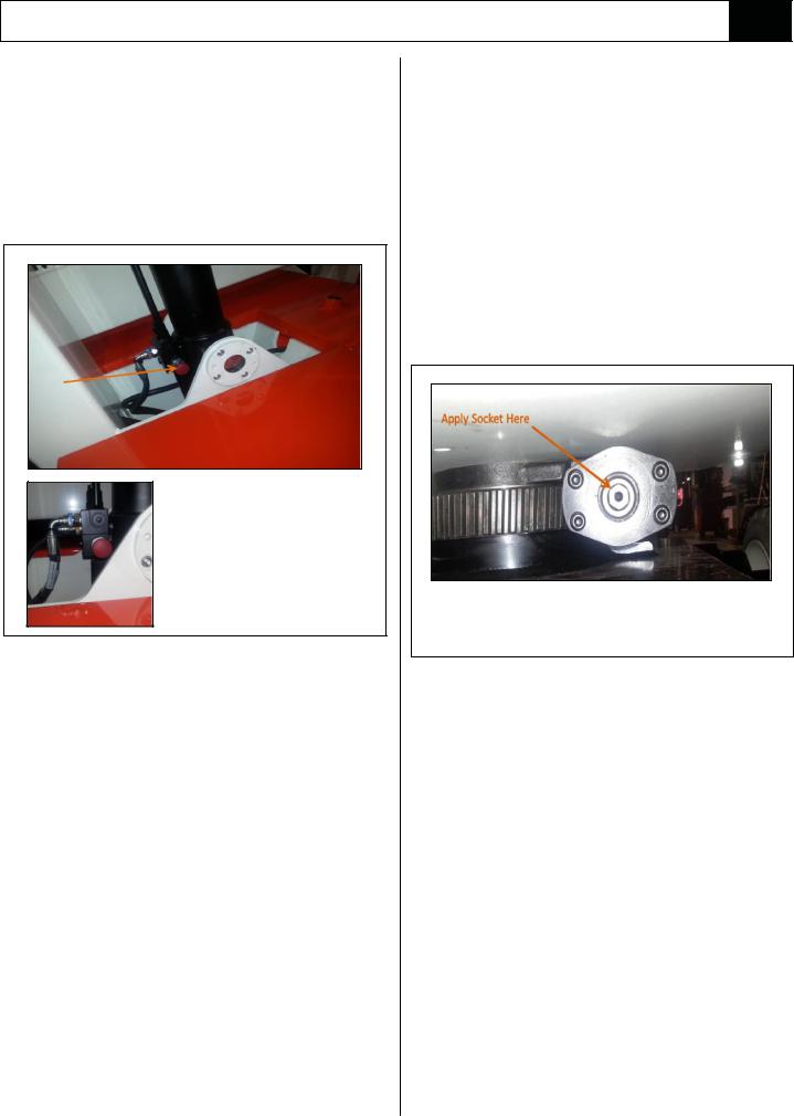
MANUAL ROTATION
1.Ensure booms are lowered as far as possible
using the emergency lowering valves, and that the Emergency Stop Button is pressed to prevent any accidental powered operation.
2.Apply a 7/8” socket wrench to shaft and turn to rotate elevating assembly.
3.Remove wrench.
To rotate the Elevating Assembly first apply a 7/8” socket wrench to the shaft and turn to rotate the Elevating Assembly. When finished remove the wrench.
Figure 3-3: Manual Rotation
MANUAL TELESCOPIC RETRACTION (SEE FIGURE 3-4)
NOTE:
Manual Tele Retraction is not required, and hence is not provided for ANSI machines.
In the event of loss of electrical power the Telescopic Cylinder can be retracted as follows:
1.Remove the cover from the chassis body.
2.The Handpump is attached to the Main Manifold
Block. Remove the Handpump Handle from the clips on the side of the Chassis and insert into the Handpump Valve as shown in Figure 3-4.
3.Operate handpump to retract the tele cylinder.
4.After use replace the Handpump Handle in the clips provided.
5.Reposition the cover on Chassis.
A38E Work Platform |
3-9 |

Section |
Operation |
|
3.4 |
|
|
|
Hand Pump |
Hydraulic |
|
Valve |
|
|
Tank |
|
|
|
|
|
|
Valve Block |
|
|
Hand Pump |
|
|
Handle |
Figure 3-4: Manual Telescopic Retraction
3-10 |
A38E Work Platform |
 Loading...