


Safety Rules and Operating Instructions

Operator Manual
UL25, UL32 & UL40
SERIAL NUMBERS 15001 TO CURRENT
WARNING
All personnel shall carefully read, understand and follow all safety rules, operating instructions and the Scaffold Industry Association's MANUAL OF RESPONSIBILITIES before performing maintenance on or operating any UpRight aerial work platform.
SAFETY RULES
NEVER elevate |
NEVER attempt to |
platform unless all |
move the UpRight |
four (4) outriggers |
Lift with people or |
have been properly |
materials on the |
installed. All |
platform or with |
outrigger screwjack |
the platform |
pads must be in solid |
elevated. |
contact with a firm |
|
surface before the |
|
platform is elevated. |
|
NEVER operate the machine |
NEVER sit, climb, or stand on the |
NEVER elevate platform without |
within ten feet of power lines. |
platform guardrails or midrail. |
first leveling the base. |
THIS MACHINE IS NOT |
|
|
INSULATED. |
|
|
NEVER use ladders, planks or other devices to increase the height of the platform. NEVER attach overhanging loads to the platform or increase the platform size.
NEVER elevate the platform if it contains more than one person or more than the rated load (see specifications on back page).
LOOK up, down and around for overhead obstructions and electrical conductors. NEVER change operating or safety systems.
NEVER use outriggers from one model on another model. CLOSE and secure cage after entering platform.
INSPECT the machine thoroughly for cracked welds, loose or missing hardware, hydraulic leaks, damaged control or power cables and loose wire connections.
NEVER use the machine as a freight or personnel elevator.
NEVER recharge battery near sparks or open flame; batteries that are being charged emit highly explosive hydrogen gas.
AFTER USE secure the work platform against unauthorized use by turning key switch off and removing key. NEVER replace any component or part with anything other than original UpRight replacement parts without
the manufacturer's consent. |
1 |
Instructions Operating and Rules Safety
Outrigger Installation |
|
Operation |
|
|
|
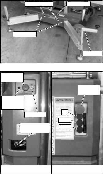
1.Remove the outriggers from storage locations on sides of mast.
2.Insert into outrigger socket in base (Figure 1).
3.Push in until locking pin engages hole in end of outrigger. Pull outward on outrigger to ensure engagement.
4.Repeat the above steps for all other outriggers. Make sure all four (4) locking pins are engaged.
5.Level the base, centering the bubble in the orbit level on the base by adjusting the screwjacks at the end of each outrigger (Figure 1). DO NOT release the tension on an outrigger, by turning counterclockwise, to level base.
6.All four (4) screwjack pads must be in solid contact with a firm surface and each outrigger indicator light must be lit before the platform is elevated.
Indicator Light |
Bubble Level |
Locking Pin |
|
|
Screwjack |
Figure 1: Installing outriggers
Emergency |
|
|
Stop Button |
|
|
|
Emergency |
|
|
Stop Button |
|
Optional |
|
|
Emergency |
|
|
Down LED |
|
|
Key Switch |
Up |
|
|
||
|
Power |
|
Emergency |
Down |
|
Lowering Valve |
||
|
||
Base Controls |
Platform Controls |
Figure 2: Controls
2
Before operating UL Lift insure that: the operator has been thoroughly trained on this machine, the operator has read, fully understands and follows this Operator Manual and the Scaffold Industry Association's MANUAL OF RESPONSIBILITIES, the unit has been properly set up with all four (4) outriggers properly installed and the base leveled, and the machine has passed the Safety Interlock Test.
Note: Platform will not elevate unless all four outriggers are properly installed with screwjack pads firmly in contact with floor and each outrigger indicator lamp lit.
1.Check for external damage to the mast.
2.For AC units connect power unit plug to extension cord (12 ga. (1.5 mm²) conductor minimum and 50 ft. (15 m) in length maximum).
Connect extension cord to properly grounded outlet of proper voltage and frequency.
3.Turn Key to ON, Key Switch is located on the left side of the mast (Figure 2).
4.Pull out on Lower Emergency Stop Button, located on the left side of the mast (Figure 2), to turn switch ON. In the event of an emergency push the button in to cut power to all controls.
5.Enter the platform by pulling out on the locking pin and lifting up on the upper half of the cage.
6.Lower upper half of the cage after entering platform making sure locking pin is engaged.
7.Check that the area above the platform is clear before elevating the platform.
8.Pull out on Emergency Stop Button, located on platform control panel (Figure 2). In the event of an emergency push the button in to cut power to all controls.
9.Push both the middle and top buttons (POWER and UP), on the Control Box (Figure 2), at the same time to elevate the platform. Release the buttons to stop.
10.Check that the area below the platform is clear before lowering the platform.
11.Push both the middle and bottom buttons (POWER and DOWN) at the same time to lower the platform. Release the buttons to stop.
12.After use, secure unit from unauthorized use by turning Key Switch to OFF and remove key.
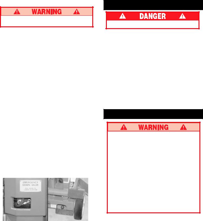
EMERGENCY LOWERING
If the platform should fail to lower, NEVER climb down the mast.
Ask a person on the ground to open the Emergency Lowering Valve to lower the platform.
Serial Number 15001 - 21690
This valve is located through a cutout in the power unit cover on the left side of the mast (Figure 3).
1.Pull the knob out and turn 1/4 turn to open the Emergency Lowering Valve.
2.To close the Emergency Lowering Valve, turn the knob until it snaps back in.
Serial Number 21691 - Current
The Emergency Control Valve Knob is located at the rear of the machine. (Figure 3).
1.Open the valve by pulling and holding the knob.
2.To close the Emergency Lowering Valve, release the knob.
Once the platform is fully lowered, be certain that the Emergency Lowering Valve is closed again. The platform will not elevate if the Emergency Lowering Valve is open.
NOTE: Optional auxiliary platform lowering circuit allows operator to lower platform when power source is interrupted. A warning light on chassis controls shines when batteries for auxiliary platform lowering circuit are low (Figure 3). Batteries for warning light are located inside chassis control box.
S/N 15001 - 21690 |
S/N 21691 - current |
Figure 3: Emergency Lowering
AFTER USE EACH DAY
1.Ensure that the platform is fully lowered.
2.Park the machine on level ground, preferably under cover.
3.Secure against vandals, children or unauthorized operation by turning the Key Switch to OFF and remove the key.
Safety Interlock Test
NEVER perform this test from the platform.
1.Properly install all four (4) outriggers and level base.
2.Release the tension on one (1) outrigger by turning the screwjack counterclockwise, until the indicator lamp is no longer lit.
3.While standing on the ground activate the control panel to elevate the platform. Platform should not elevate.
4.Re-level the base with all four (4) outriggers then repeat step 2 with another outrigger.
5.Repeat steps 2 , 3 & 4 until all four (4) outriggers have been tested.
DO NOT use a machine that elevates when the tension has been released on an outrigger. Machine must be repaired before using.
Battery Maintenance
Hazard of explosive gas mixture. Keep sparks, flame and smoking materials away from battery.
Always wear safety glasses when working with batteries.
Battery fluid is highly corrosive. Rinse away any spilled fluid thoroughly with clean water.
Always replace battery with UpRight battery or manufacturer approved replacement weighing at least 52 lbs. (23.6 kg) each.
Check battery fluid level daily, especially if work platform is being used in a warm, dry climate.
If electrolyte level is less than 3/8 in. (10 mm) above plates add distilled water only. DO NOT use tap water with high mineral content, it will shorten battery life.
Keep terminals and tops of batteries clean.
Refer to the Service Manual to extend battery life and for complete service instructions.
3
 Loading...