

Page 1
kÉï=~ë=çÑW=
MPKOMNS
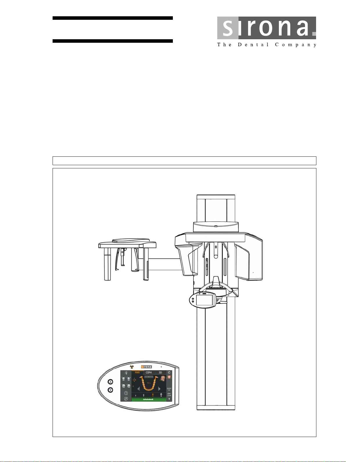
loqelmelp=pi=Oa=L=loqelmelp=pi=Oa=`ÉéÜ=
loqelmelp=pi=Pa=L=loqelmelp=pi=Pa=`ÉéÜ
fелн~дд~нбзе=oЙимбкЙгЙенл
bеЦдблЬ
bеЦдблЬ
Title page
=
Page 2

Page 3

Sirona Dental Systems GmbH Table of contents
Installation Requirements ORTHOPHOS SL 2D / 3D
Table of contents
1
2
3
General data............................................................................................................. 5
1.1 Notes on the installation prerequisites .......................................................... 5
1.2 Structure of the document............................................................................. 6
1.2.1 Identification of the danger levels..................................................... 6
1.2.2 Formats and symbols used .............................................................. 6
Safety instructions .................................................................................................... 7
2.1 Product safety ............................................................................................... 7
2.2 Combination with other units......................................................................... 7
2.3 Shielding of room .......................................................................................... 7
2.4 Radiotelephones ........................................................................................... 7
2.5 Electromagnetic compatibility........................................................................ 7
2.6 Electrical installation...................................................................................... 7
Checklist of installation prerequisites ....................................................................... 8
3.1 Purpose of the checklist ................................................................................ 8
3.2 Persons or companies performing inspection ............................................... 9
3.3 Construction requirements ............................................................................ 11
bеЦдблЬ
3.4 IT Hardware .................................................................................................. 14
3.5 Network ......................................................................................................... 18
3.6 Data processing ............................................................................................ 19
3.7 List of measures............................................................................................ 22
4
Preparations ............................................................................................................. 23
4.1 Installation options ........................................................................................ 23
4.2 Mounting options........................................................................................... 25
4.3 On-site installation: Schematic diagram........................................................ 26
4.4 Emergency stop switch (if legally required)................................................... 28
4.5 On-site installation for PC/networks .............................................................. 30
4.6 For USA and Canada.................................................................................... 32
4.6.1 Emergency Stop for Canada............................................................ 33
64 95 183 D3632
D3632.021.01.03.02 03.2016
3
Page 4

Table of contents Sirona Dental Systems GmbH
Installation Requirements ORTHOPHOS SL 2D / 3D
5
Dimensions, technical data ...................................................................................... 34
5.1 Dimensions 1:20 ORTHOPHOS SL.............................................................. 34
5.1.1 Top view........................................................................................... 34
5.1.2 Front view......................................................................................... 35
5.1.3 Top view with floor stand.................................................................. 36
5.1.4 Front view with floor stand ............................................................... 37
5.1.5 Top view with Ceph left .................................................................... 38
5.1.6 Front view with Ceph left.................................................................. 39
5.1.7 Top view with Ceph right.................................................................. 40
5.1.8 Front view with Ceph right................................................................ 41
5.2 Technical data............................................................................................... 42
5.2.1 Unit data........................................................................................... 42
5.2.2 Operating and transport conditions .................................................. 42
5.2.3 Weight and packaging...................................................................... 42
5.2.4 Certification and registration ............................................................ 43
6
Electromagnetic compatibility................................................................................... 44
6.1 Accessories................................................................................................... 44
6.2 Electromagnetic emission ............................................................................. 44
6.3 Interference immunity.................................................................................... 45
6.4 Working clearances....................................................................................... 47
4 D3632.021.01.03.02 03.2016
64 95 183 D3632
Page 5

Sirona Dental Systems GmbH 1General data
Installation Requirements ORTHOPHOS SL 2D / 3D 1.1Notes on the installation prerequisites
General data
1
1.1
Notes on the installation prerequisites
This document describes the installation conditions for the X-ray units
ORTHOPHOS SL 2D,
ORTHOPHOS SL 2D Ceph,
ORTHOPHOS SL 3D,
ORTHOPHOS SL 3D Ceph
Subsequent installation is described in the
ORTHOPHOS SL Installation Instructions (REF 64 95 142).
bеЦдблЬ
64 95 183 D3632
D3632.021.01.03.02 03.2016
5
Page 6
1General data Sirona Dental Systems GmbH
1.2Structure of the document Installation Requirements ORTHOPHOS SL 2D / 3D
1.2
Structure of the document
1.2.1 Identification of the danger levels
To prevent personal injury and material damage, please observe the
warning and safety information provided in the present operating
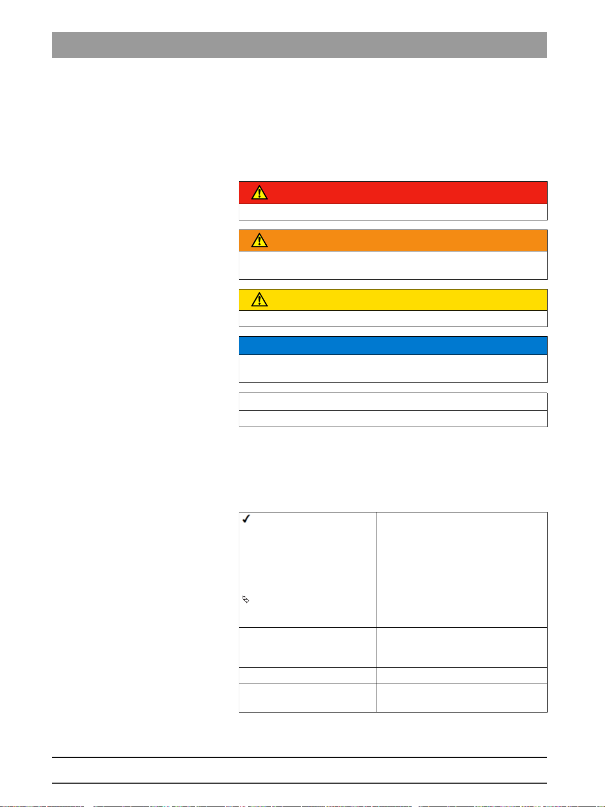
instructions. Such information is highlighted as follows:
DANGER
An imminent danger that could result in serious bodily injury or death.
WARNING
A possibly dangerous situation that could result in serious bodily injury
or death.
CAUTION
A possibly dangerous situation that could result in slight bodily injury.
NOTICE
A possibly harmful situation which could lead to damage of the product
or an object in its environment.
IMPORTANT
Application instructions and other important information.
Tip: Information on making work easier.
1.2.2 Formats and symbols used
The formats and symbols used in this document have the following
meaning:
Prerequisite
1. First action step
2. Second action step
or
➢ Alternative action
Result
➢ Individual action step
See "Formats and symbols
used [ → 6]"
● List Designates a list.
"Command / menu item" Indicates commands, menu items or
Requests you to do something.
Identifies a reference to another text
passage and specifies its page
number.
quotations.
6 D3632.021.01.03.02 03.2016
64 95 183 D3632
Page 7
Sirona Dental Systems GmbH 2Safety instructions
Installation Requirements ORTHOPHOS SL 2D / 3D 2.1Product safety
Safety instructions
2
2.1
2.2
Product safety
Product safety
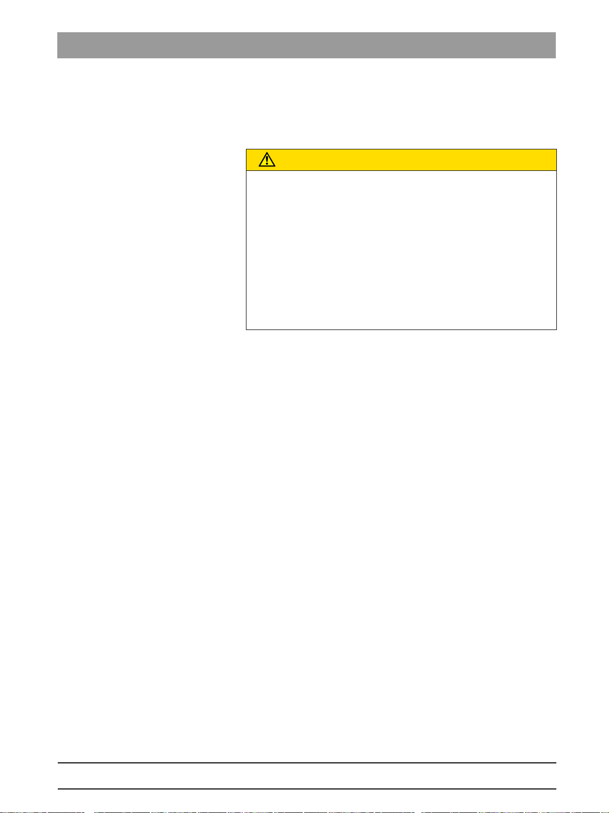
CAUTION
Risk to product safety
For reasons of product safety, this product may be operated only with
original Sirona accessories or third-party accessories expressly
approved by Sirona.
The user assumes the risk of using non-approved accessories.
Recommendation If any equipment not approved by Sirona is
connected, it should comply with the applicable standards:
- IEC 60950 for information technology equipment (e.g. PC)
- IEC 60601-1 for medical electrical equipment.
In case of doubt, contact the manufacturer of the system components.
Combination with other units
Combination with other un its in accordance with IEC 60601-1 -1
Putting together or altering a medical electrical system by combining with
other devices in accordance with IEC 60601-1 (safety requirements for
medical electrical systems) is subject to the obligation to ensure
compliance with the requirements of this provision for patient safety, the
operator and the environment.
bеЦдблЬ
2.3
2.4
2.5
2.6
Shielding of room
Panoramic X-ray
When using the ORTHOPHOS SL X-ray unit, proper shielding of the
room and operator position is essential.
It is the installer's responsibility to ensure that all local radiation
regulations and safety measures are met.
Radiotelephones
Mobile RF communications equipment can affect electro-medical
equipment. Therefore, the use of mobile wireless phones in medical office
or hospital environments must be prohibited.
Electromagnetic compatibility
The unit should not be operated in the immediate vicinity of other devices.
If this proves to be unavoidable, the unit should be monitored to ensure
that it is operating properly.
Electrical installation
The electrical installation must be made in compliance with DIN VDE
0100-710.
64 95 183 D3632
D3632.021.01.03.02 03.2016
7
Page 8

3Checklist of installation prerequisites Sirona Dental Systems GmbH
3.1Purpose of the checklist Installation Requirements ORTHOPHOS SL 2D / 3D
Checklist of installation prerequisites
3
3.1
We recommend performing an inspection of the circumstances on location 4 weeks prior to installation.
This can help ensure a smooth procedure on the day that the ORTHOPHOS SL device is actually installed. The
checklist of this document contains the most important items to take into consideration.
An installed and executable version of the SIDEXIS 4 X-ray software must be installed as a prerequisite to operating
the ORTHOPHOS SL unit.
DANGER! It cannot be used with the SIDEXIS XG version.
Purpose of the checklist
8 D3632.021.01.03.02 03.2016
64 95 183 D3632
Page 9

Sirona Dental Systems GmbH 3Checklist of installation prerequisites
Installation Requirements ORTHOPHOS SL 2D / 3D 3.2Persons or companies performing inspection
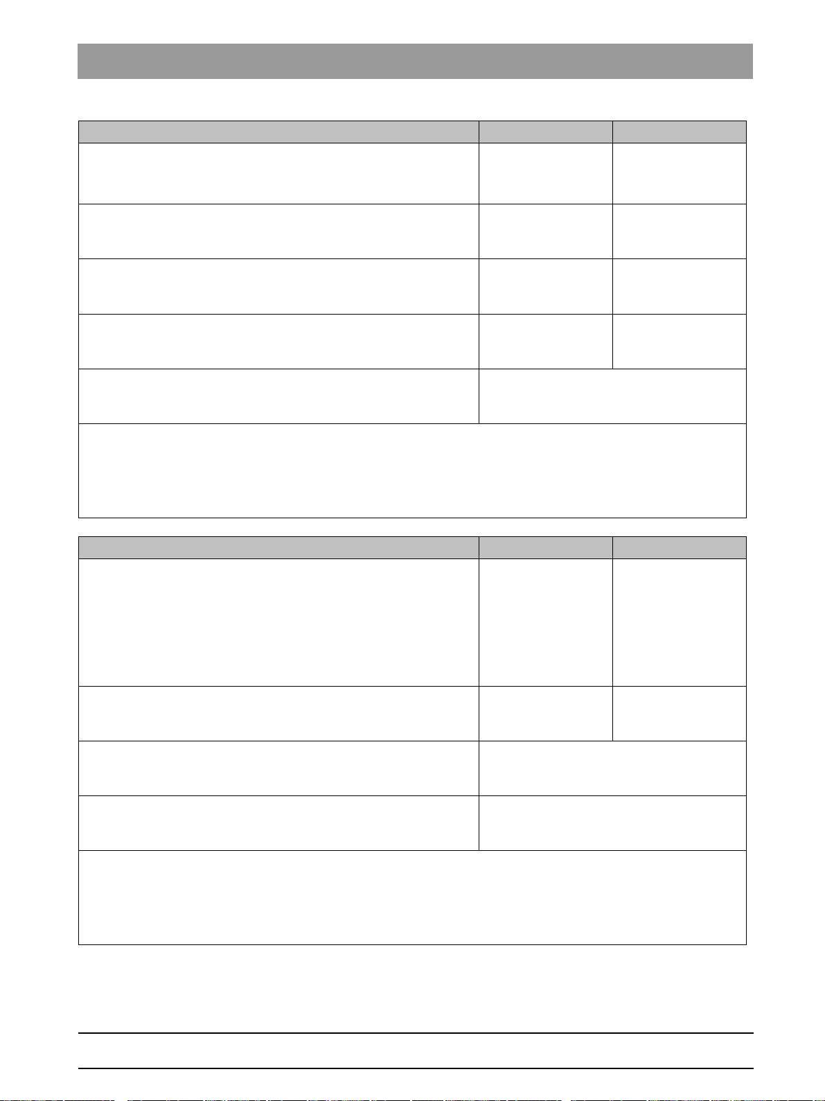
3.2
List of the persons/companies performing inspection on location:
Specialized dealers:
Date of the inspection:
Present/company:
Present/company:
Present/company:
Installation site / practice / clinic:
Last name, first name:
Persons or companies performing inspection
bеЦдблЬ
Street:
Postal code / city:
Phone:
E-mail:
Special field of system owner:
@
64 95 183 D3632
D3632.021.01.03.02 03.2016
9
Page 10

3Checklist of installation prerequisites Sirona Dental Systems GmbH
3.2Persons or companies performing inspection Installation Requirements ORTHOPHOS SL 2D / 3D
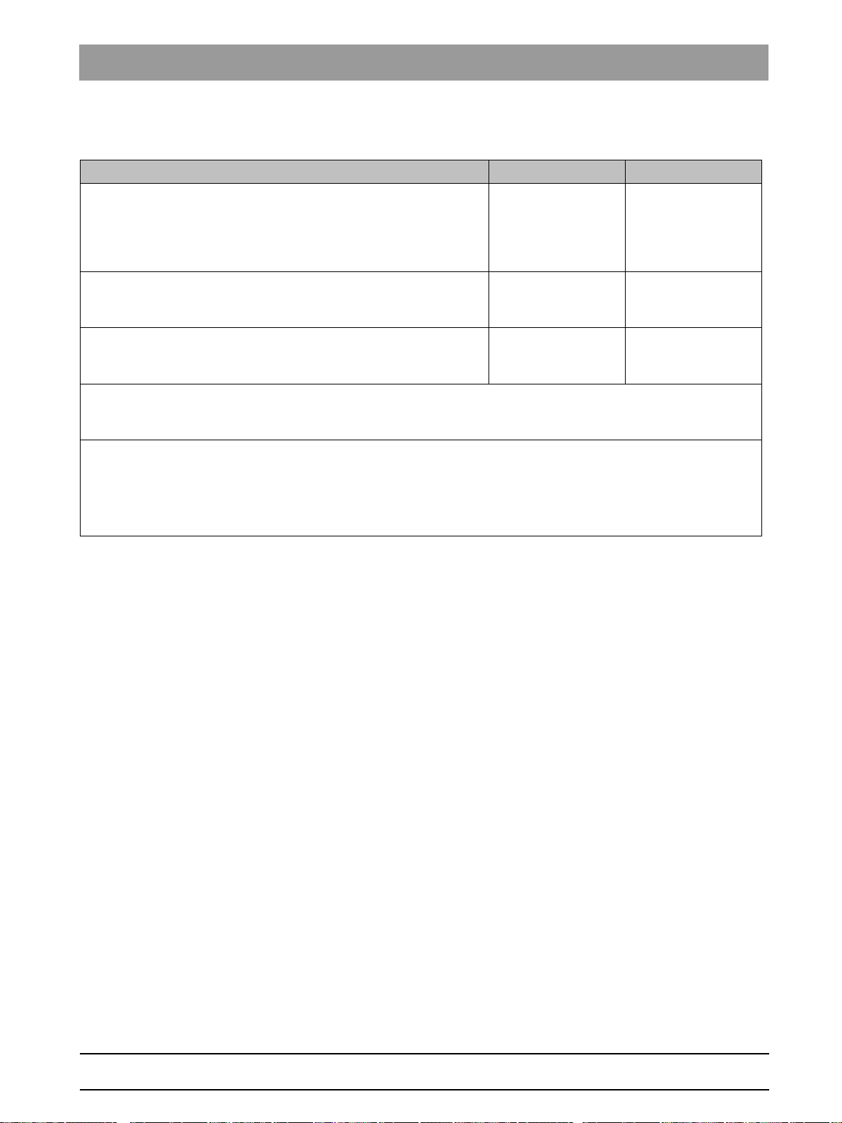
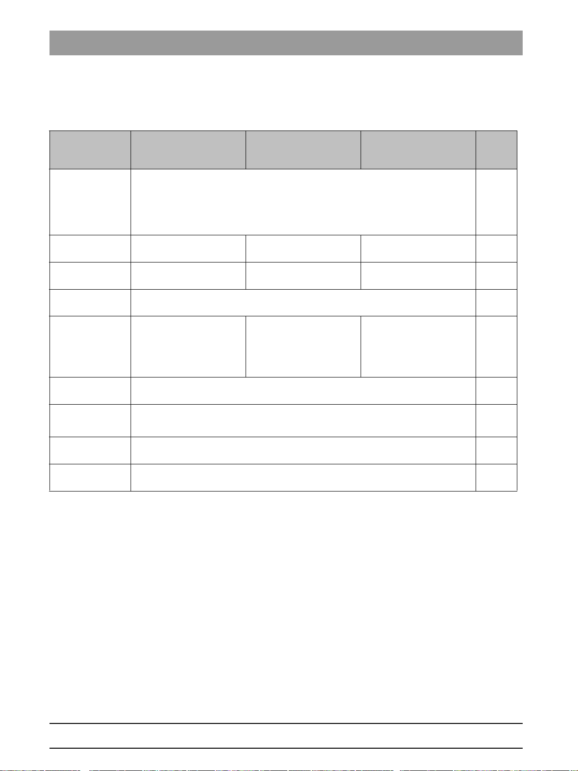
List of contact persons on-site:
Function First name/Last
Phone Cell phone E-mail
name:
Service engineer
IT specialist
Specialist advisors
Administrator
Expert
Clinic engineer
Professor
Dentist
Day/date of planned installation:
Time:
Installation postponement to
day/date (if applicable):
Time
10 D3632.021.01.03.02 03.2016
64 95 183 D3632
Page 11
Sirona Dental Systems GmbH 3Checklist of installation prerequisites
Installation Requirements ORTHOPHOS SL 2D / 3D 3.3Construction requirements
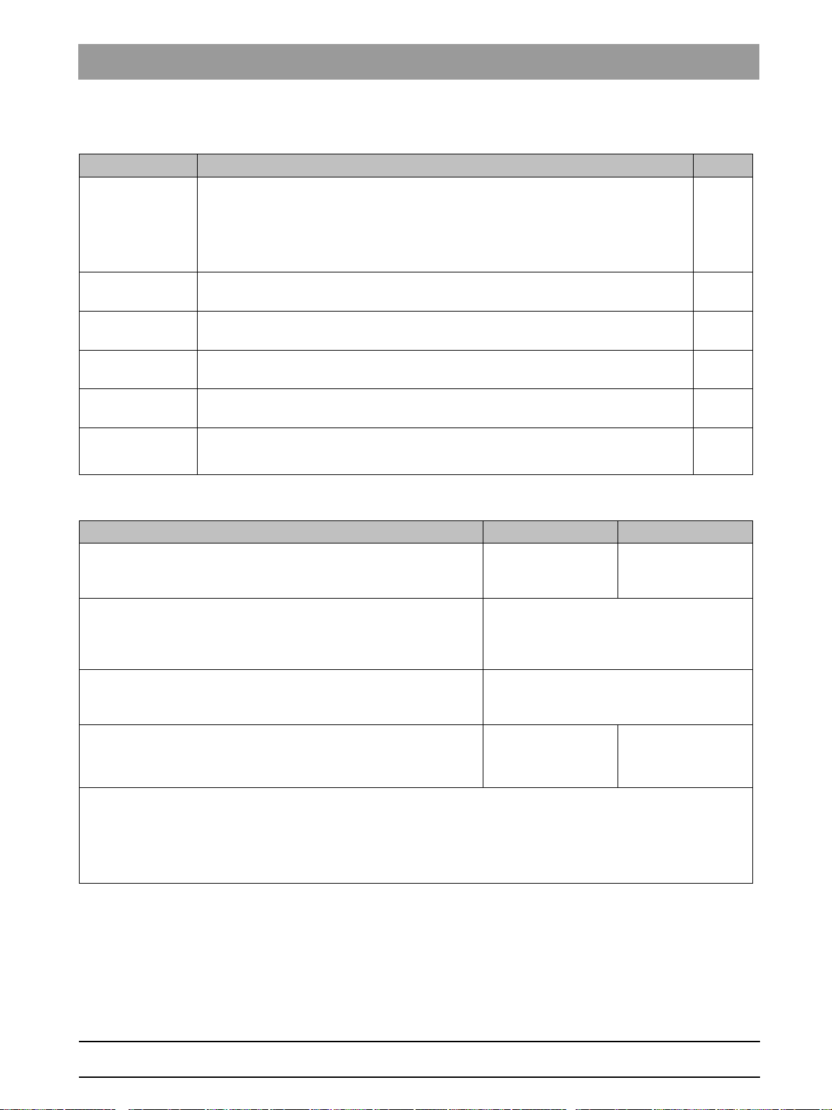
3.3
Transport paths ☑
● Clarify and/or walk along unit transport path from delivery
location to installation site, measuring doorways and
passageways
(For dimensions/weight, see Weight and packaging [ → 42])
Transport path OK?
● Elevator available and large enough for transporting the unit?
● Appropriate transport personnel provided.
● Person responsible:
● Remarks/Tasks:
Construction requirements
☐ Yes ☐ No
☐ Yes ☐ No
☐ Yes ☐ No
bеЦдблЬ
64 95 183 D3632
D3632.021.01.03.02 03.2016
11
Page 12

3Checklist of installation prerequisites Sirona Dental Systems GmbH
3.3Construction requirements Installation Requirements ORTHOPHOS SL 2D / 3D
Installation site ☑
● Installation location:
Unit location:
Building number:
Room name/number:
● Is the room large enough?
(see Dimensions 1:20 ORTHOPHOS SL [ → 34]
)
☐ Yes ☐ No
● Radiation protection plan available?
☐ Yes ☐ No
ATTENTION!
If the room height is less than 2.27 m (89 3/8") or 2.30 m (90 1/2") for
installation with the floor stand, the maximum travel must be limited.
● Room height measures at least 2100 mm (82 3/4")?
Maximum unit height without floor stand 2249 mm (88 1/2")
Maximum unit height with floor stand 2279 mm (89 1/4")
☐ Yes ☐ No
● Underfloor heating available?
If yes, use 2 wall brackets.
☐ Yes ☐ No
● Is there carpet at the unit's installation location?
If yes, remove carpet from under the unit.
● Information about the characteristics/material of the wall
available?
If possible perform test drilling!
● Required extraction forces ensured?
(for wall plugs, see Installation options [ → 23])
ATTENTION!
If the condition of the wall is not sufficient, a floor stand can be used.
The upper wall fastening for immobilizing the unit is absolutely
essential when installing it on the floor stand!
● Installation on the wall with or without floor stand
(see Mounting options [ → 25])?
● Temporary storage facilities for the styrofoam parts available?
The unit should be brought to the installation location with the
styrofoam parts; one of the installation aids should also be
available. These should be temporarily stored until collection.
● Remarks/Tasks:
☐ Yes ☐ No
☐ Yes ☐ No
☐ Yes ☐ No
☐ with ☐ without
☐ Yes ☐ No
12 D3632.021.01.03.02 03.2016
64 95 183 D3632
Page 13
Sirona Dental Systems GmbH 3Checklist of installation prerequisites
Installation Requirements ORTHOPHOS SL 2D / 3D 3.3Construction requirements
Electrical connection: ☑
● Fusing of the unit termination 3x2.5mm2 (14 AWG) 230/ B25A,
2
for 3x1.5mm
may be connected.
● Checked internal line resistance? (Max. 0.8 ohms)
● Connection option available for second protective ground wire?
If no connection option is available, one must be retrofitted!
● Other large electrical units (e.g. air conditioning systems, fan
motors) in the vicinity?
If yes, which (EMC influences)?
● Clearance of the large electrical units to ORTHOPHOS SL?
● Remarks/Tasks:
(16AWG) B16A/B20A only the ORTHOPHOS SL
☐ Yes ☐ No
☐ Yes ☐ No
☐ Yes ☐ No
☐ Yes ☐ No
__________________m
Type of remote control installation: ☑
● Type of remote control required (see Installation options [ → 23]):
– In the room
– Outside without coiled cable
– Outside with coiled cable
● Ductwork available?
● Diameter of the ductwork?
(Min. diameter 10mm (3/8"))
● Removal? (Length of the special control cable supplied 15m
(590 1/2"))
● Remarks/Tasks:
☐ Yes
☐ Yes
☐ Yes
☐ Yes ☐ No
__________________mm
__________________m
☐ No
☐ No
☐ No
bеЦдблЬ
64 95 183 D3632
D3632.021.01.03.02 03.2016
13
Page 14
3Checklist of installation prerequisites Sirona Dental Systems GmbH
3.4IT Hardware Installation Requirements ORTHOPHOS SL 2D / 3D
3.4
IT Hardware
Requirements for workstation PCs, service engineer
Requirements on workstation PCs when using a separate RCU
Requirements
for 2D workstation
Operating system: ● Windows 7 Professional/Ultimate (64 bit)
● Windows 8.1 Professional (64 bit)
● Windows 10
IMPORTANT: An Internet connection is required from Windows 8.
Processor ≥ 2.3 GHz DualCore
with SSE3 support
Main memory ≥ 4 GB ≥ 8 GB ≥ 8 GB
Hard disk ≥ 500 GB free hard disk space
Graphics card DirectX 9.0c graphics card
(512 MB RAM dedicated or
Intel Onboard graphics)
Graphics settings Minimum 1280x1024 pixels
Recommended 1600x1200 pixels ☐
Drive ● DVD ROM
● DVD RAM (to use Wrap & Go)
Screen Suitable for diagnosis applications
Software ● Acrobat Reader 8.0, contained on DVD
(required for the PDF test report function) ☐
Requirements
for 3D workstation
≥ 2.3 GHz QuadCore
with SSE3 support
DirectX 10 graphics card
(1GB RAM dedicated or
Intel Onboard graphics)
with WDDM driver 1.0 or
higher
Requirements for
2D/3D workstation with
panorama editor
≥ 2.3 GHz QuadCore
with SSE3 support ☐
(16 GB recommended) ☐
DirectX 10 graphics card
(1GB RAM dedicated or
Intel Onboard graphics)
with WDDM driver 1.0 or
higher
Fulfilled
☐
☐
☐
☐
☐
14 D3632.021.01.03.02 03.2016
64 95 183 D3632
Page 15
Sirona Dental Systems GmbH 3Checklist of installation prerequisites
Installation Requirements ORTHOPHOS SL 2D / 3D 3.4IT Hardware
Requirements on RCU hardware, service engineer
Requirements on RCU hardware
Requirements Fulfilled
Operating system: ● Windows 7 Professional/Ultimate (64 bit)
● Windows 8.1 Professional (64 bit)
● Windows 10
IMPORTANT: An Internet connection is required from Windows 8.
Processor ≥ 2.3 GHz QuadCore with SSE3 support, only intel ≥ i73xx
Main memory ≥ 16 GB
Hard disk ≥ 2 TB of free hard disk space
Graphics card Only for combined use as workstation on one PC, see above.
Drive ● DVD ROM
● DVD RAM (to use Wrap & Go)
☐
☐
☐
☐
☐
☐
bеЦдблЬ
Workstations/RCU ☑
● Is a diagnostic monitor available?
At least one diagnostic monitor must be available in the practice.
● Number of planned workstations
It is advisable to locate a workstation PC near the ORTHOPHOS
SL for the purpose of readying the unit for exposure.
● Plan/determine location of RCU (room)
● Is a switch available? ☐ Yes
● Remarks/Tasks:
☐ Yes ☐ No
__________________workstations
☐ 1 GBit
☐ No
64 95 183 D3632
D3632.021.01.03.02 03.2016
15
Page 16

3Checklist of installation prerequisites Sirona Dental Systems GmbH
3.4IT Hardware Installation Requirements ORTHOPHOS SL 2D / 3D
SQL/Fileserver ☑
● Are SIDEXIS databases already installed?
☐ Yes ☐ No
● If yes, which version of the SIDEXIS database?
(Patients.paf, Pdata.mdb, SQL-Express or SQL)
___________________________________
● Is migration necessary?
☐ Yes ☐ No
● SQL server available?
Microsoft SQL-Express is included in the scope of supply!
– SQL-Server version
– SQL-Server name
● File server installed (separate server for image database only)?
– Windows release with full access
– Operating system/version
– Name of computer
– IP address
– Processor performance (clock frequency)
– Available RAM?
– Available hard disk storage?
● Number of exposures planned. (Approx. 1GB per volume
exposure are currently stored in the database!
3D: Approx. 100 - 650 MB database; data container 500 MB 2300 MB
2D: Database approx. 1000 MB; data container 1700 MB
☐ Yes
☐ No
________________
________________
☐ Yes
☐ Yes
☐ No
☐ No
________________
________________
_____ . _____ . _____ . _____
________________
________________ GB
________________ GB
________________
– Per month?
– Volume per month x 12 = volume per year
– Approx. memory required
– Depending on this, is a backup system available?
– Is a backup system planned?
________________
________________
______________GB
☐ Yes
☐ Yes
☐ No
☐ No
64 95 183 D3632
16 D3632.021.01.03.02 03.2016
Page 17

Sirona Dental Systems GmbH 3Checklist of installation prerequisites
Installation Requirements ORTHOPHOS SL 2D / 3D 3.4IT Hardware
SQL/Fileserver ☑
ATTENTION!
Network Attached Storage (NAS) units
The use of LINUX based Network Attached Storage (NAS) units for
PDATA can cause problems.
● Remarks/Tasks:
bеЦдблЬ
64 95 183 D3632
D3632.021.01.03.02 03.2016
17
Page 18

3Checklist of installation prerequisites Sirona Dental Systems GmbH
3.5Network Installation Requirements ORTHOPHOS SL 2D / 3D
3.5
Network ☑
● The entire network must be equipped with 1 GBit Ethernet!
–Cat 5e/Cat 6 ☐ 1 GBit/sec
● Network connection for ORTHOPHOS SL available?
● Network connection available at all workstations?
● Network connection for RCU available?
IMPORTANT!
It is advisable to locate a workstation PC near the ORTHOPHOS SL
for the purpose of readying the unit for exposure.
● Network configuration plan available?
Network
☐ Yes ☐ No
☐ Yes ☐ No
☐ Yes ☐ No
☐ Yes ☐ No
☐ Yes ☐ No
● Have the network jacks been certified?
● Network certificate present?
● Network installation company?
● Remarks/Tasks:
☐ Yes ☐ No
☐ Yes ☐ No
18 D3632.021.01.03.02 03.2016
64 95 183 D3632
Page 19

Sirona Dental Systems GmbH 3Checklist of installation prerequisites
Installation Requirements ORTHOPHOS SL 2D / 3D 3.6Data processing
3.6
IP addresses/Firewall ☑
● TCP/IP address range
● Subnet mask
● Are addresses already defined/present?
● Is there a DCHP server (dynamic TCP/IP address assignment)?
ATTENTION!
A static address is required for the ORTHOPHOS SL and the RCU!
It must not lie in the dynamic address range!
● ORTHOPHOS SL
● RCU:
Data processing
______ . ______ . ______ . ______ - ______ . ______ . ______ . ______
______ . ______ . ______ . ______
☐ Yes ☐ No
☐ Yes ☐ No
bеЦдблЬ
______ . ______ . ______ . ______
● Workstation PCs:
● Standard gateway:
● Antivirus software available?
● Is a firewall installed?
– Software or hardware firewall?
● Remarks/Tasks:
______ . ______ . ______ . ______
______ . ______ . ______ . ______ - ______ . ______ . ______ . ______
______ . ______ . ______ . ______
☐ Yes ☐ No
☐ Yes
☐ SW
☐ HW
☐ No
64 95 183 D3632
D3632.021.01.03.02 03.2016
19
Page 20

3Checklist of installation prerequisites Sirona Dental Systems GmbH
3.6Data processing Installation Requirements ORTHOPHOS SL 2D / 3D
IP addresses/Firewall ☑
● The following ports must be open for configuration and operation!
● ORTHOPHOS SL 12835
12836
12837
12838
12839
12935
12936
12937
12938
443
● RCU 52837
● SIDEXIS 4 Server 42916
42927
42928
● Remarks/Tasks:
Practice administration programs ☑
● Are connections to the practice administration programs, etc.
installed?
☐ Yes ☐ No
● If yes, which system (manufacturer + name)?
● Remarks/Tasks:
20 D3632.021.01.03.02 03.2016
64 95 183 D3632
Page 21

Sirona Dental Systems GmbH 3Checklist of installation prerequisites
Installation Requirements ORTHOPHOS SL 2D / 3D 3.6Data processing
DICOM ☑
● Is a DICOM installation already present?
☐ Yes
☐ No
– Which version?
– Configuration?
● Is a DICOM connection required?
● If yes, what is required?
– SIDICOM WLS or QR
Which functionalities should be supported?
In this case, the DICOM questionnaire must be completed!
– DICOM Removable Media (included in delivery)
● Remarks/Tasks:
________________
________________
☐ Yes ☐ No
☐ Yes
☐ Yes
☐ No
☐ No
bеЦдблЬ
64 95 183 D3632
D3632.021.01.03.02 03.2016
21
Page 22

3Checklist of installation prerequisites Sirona Dental Systems GmbH
3.7List of measures Installation Requirements ORTHOPHOS SL 2D / 3D
3.7
What Who When
List of measures
Inspection of installation requirements performed on:
from: Depot: Name: Signature:
Customer: Name: Signature:
64 95 183 D3632
22 D3632.021.01.03.02 03.2016
Page 23

Sirona Dental Systems GmbH 4Preparations
Installation Requirements ORTHOPHOS SL 2D / 3D 4.1Installation options
Preparations
4
4.1
Installation options
bеЦдблЬ
64 95 183 D3632
D3632.021.01.03.02 03.2016
A Standard installation
without remote control with release button on the coiled cable
Unit
in the treatment room.
B Installation version 1
Unit
with remote control
button on the coiled cable
Length of the special control cable supplied 15m (590 1/2").
C Installation version 2
Unit
with remote control
button on the coiled cable
outside the X-ray room
.
outside the X-ray room
.
without release
with release
23
Page 24

4Preparations Sirona Dental Systems GmbH
4.1Installation options Installation Requirements ORTHOPHOS SL 2D / 3D
CAUTION
Wall plugs!
Each wall plug used to attach the unit must withstand an extraction force
of 700 N.
● Depending on the given wall construction, buy the corresponding
special wall plugs from a specialized dealer or make an anchor plate.
● With remote control: When using a door contact: Run shielded 2-wire
2
cable (0.22mm
When using X-ray warning lamp is used: Run a 3-wire cable
2
(1.5mm
) (16AWG) to the warning lamp.
DANGER!
A maximum load of 50 W is permissible and no additional circuit may
be connected.
/ 24 AWG) to remote control.
24 D3632.021.01.03.02 03.2016
64 95 183 D3632
Page 25

Sirona Dental Systems GmbH 4Preparations
C
B
A
Installation Requirements ORTHOPHOS SL 2D / 3D 4.2Mounting options
4.2
Mounting options
bеЦдблЬ
A Standard version
Wall-mounted installation with 1 wall holder
fastening if both wall and floor installation are possible on-site.
B Option 1: with second wall holder
Wall-mounted installation with 2 wall holders
fastening) if only wall installation is possible on-site.
C Option 2: with floor stand and wall holder
Installation using a floor stand and 1 wall holder
possible to mount the unit on the wall and on the floor on-site and
x-rays are often taken while the patient is seated on a chair →
better positioning of seated patient.
(short) and floor
(short) (and no floor
(long) if it is
64 95 183 D3632
D3632.021.01.03.02 03.2016
25
Page 26

4Preparations Sirona Dental Systems GmbH
4.3On-site installation: Schematic diagram Installation Requirements ORTHOPHOS SL 2D / 3D
4.3
On-site installation: Schematic diagram
A Minimum room height 2100 mm
B Mounting bracket
C Unit center of column
D Minimum clearance Ceph left
E Minimum clearance Ceph right
F USA/Canada: Wooden beam
G Remote control
H Cable bushing
DANGER
Fixed connection!
The installation of a power plug instead of the prescribed fixed (hardwired) connection violates international medical regulations and is
prohibited.
In case of a fault, you would thus endanger the life and limb of the
patient, the operator or other persons.
26 D3632.021.01.03.02 03.2016
64 95 183 D3632
Page 27

Sirona Dental Systems GmbH 4Preparations
Installation Requirements ORTHOPHOS SL 2D / 3D 4.3On-site installation: Schematic diagram
NOTICE
Only the control cable supplied may be used. It is installed during
installation of the unit.
1. Conduit for remote control
If the shielded control cable (supplied, length 15m (590 1/2")) is flushmounted, a conduit must be used! ∅ int. min. 10mm, maximum
permissible length 13m (512")!
2. Distributor box for remote control.
A distributor box with strain relief option must be provided near/
behind the unit column.
3. Distributor box with power cable and terminal strip Recommendation:
2
A 3-wire power cable (N, L, PE, at least 3x2.5 mm
AWG or 12 AWG)) must be connected to the central distributor of the
building installation. Circuit breaker LS B25A.
– For a building inst allat ion wi th 3 x 1 .5 mm
/ 14 AWG) and a circuit breaker LS B16A/B20A, only the
ORTHOPHOS SL or devices which do not create a hazard for the
patient when the circuit breaker is tripped and no data processing
systems whatsoever may be connected.
or 3x4 mm2 (14
2
/ 3 x 2.5mm2 (16 AWG
bеЦдблЬ
4. Install distributor box for second protective ground wire.
WARNING
Install connection option for second protective ground wire. Second
protective ground wire is prefabricated with 5 - 2.5 DIN 46234 cable lug.
The cable lug can be removed when the cable is connected to a
terminal.
64 95 183 D3632
D3632.021.01.03.02 03.2016
27
Page 28

4Preparations Sirona Dental Systems GmbH
4.4Emergency stop switch (if legally required) Installation Requirements ORTHOPHOS SL 2D / 3D
4.4
Emergency stop switch (if legally required)
A Remote control
B Emergency stop switch;
ATTENTION In Japan, the emergency stop switch is a legal
requirement
For Canada, see section Emergency Stop for Canada [ → 33]
C Unit center of column
D Power cable
E Second protective ground wire
1. Install emergency stop switch in the power cable. Attach switch so
that it is easily accessible, but cannot be switched accidentally.
2. Distributor box with power cable and terminal strip
Recommendation: A 3-wire power cable (N, L, PE, at least 3x2.5
2
or 3x4 mm2 (14 AWG or 12 AWG)) must be connected to the
mm
central distributor of the building installation.
Circuit breaker LS B25A.
28 D3632.021.01.03.02 03.2016
64 95 183 D3632
Page 29

Sirona Dental Systems GmbH 4Preparations
Installation Requirements ORTHOPHOS SL 2D / 3D 4.4Emergency stop switch (if legally required)
3. The cable to the emergency stop switch must have at least the same
diameter as the power cable.
2
– For a building inst allat ion wi th 3 x 1 .5 mm
/ 14 AWG) and a circuit breaker LS B16A/B20A, only the
ORTHOPHOS SL or devices which do not create a hazard for the
patient when the circuit breaker is tripped and no data processing
systems whatsoever may be connected.
4. Install distributor box for second protective ground wire.
/ 3 x 2.5mm2 (16 AWG
WARNING
Install connection option for second protective ground wire. Second
protective ground wire is prefabricated with 5 - 2.5 DIN 46234 cable lug.
The cable lug can be removed when the cable is connected to a
terminal.
bеЦдблЬ
64 95 183 D3632
D3632.021.01.03.02 03.2016
29
Page 30

4Preparations Sirona Dental Systems GmbH
4.5On-site installation for PC/networks Installation Requirements ORTHOPHOS SL 2D / 3D
4.5
On-site installation for PC/networks
A Network
B Fiber-optic cable SC → Ethernet cable RJ45
* The media converted is required if there is no fiber-optic
cable with SC connector available.
1. Length of the patch cable supplied with the media converter: 5m
(197")
Space available for media converter either behind the column are at
the PC. A power socket is required for the media converter.
2. If the Ethernet cable is flush-mounted, a conduit must be used ∅ int.
min. 21mm (7/8") (sufficient bending radius for 4cm (1 1/2")
connector).
Strain relief provided!
– Recommendation: To avoid malfunctions, do not lay the cable
with other cables.
3. At least five permanently installed Schuko plugs are required for RCU
server, workstation PC, monitors, switches etc. (not included in scope
of supply).
4. Network: 1 GBit Ethernet recommended.
Communication connection: RJ45 for LAN cable.
30 D3632.021.01.03.02 03.2016
64 95 183 D3632
Page 31

Sirona Dental Systems GmbH 4Preparations
Installation Requirements ORTHOPHOS SL 2D / 3D 4.5On-site installation for PC/networks
5. For PCs which are connected to an X-ray unit and are in the same
room as the unit, an additional protective ground wire is required
2
with cable lug 4 - 6 DIN 46234 CU) in accordance with IEC
(4mm
60601-1.
bеЦдблЬ
64 95 183 D3632
D3632.021.01.03.02 03.2016
31
Page 32

4Preparations Sirona Dental Systems GmbH
4.6For USA and Canada Installation Requirements ORTHOPHOS SL 2D / 3D
4.6
For USA and Canada
A Distribution panel with an overcurrent circuit breaker rated
for 25 A
B 3x AWG see chart
C Ground
D Distributor box
Minimum
wire size
No 12 AWG →→→→→→→→→
No 10 AWG →→→→→→→→→→→→→→
No 8 AWG →→→→→→→→→→→→→→→→→→→→→→→→→
Wire run distance in feet
25 50 75 100 125
Wire Size for Power Line
● The unit is designed to operate on a nominal 200 - 240 VAC line.
Permitted line voltage variation ±10%.
On request, the local Electrical Utility Company will perform a voltage
regulation test to verify the line quality.
● The distributor box should be installed in the position as shown on
page Principle of On-site Installation [ → 26].
● To assure proper line quality, a separate three-core grounded power
cable connected directly to the central distribution panel with an
overcurrent circuit breaker rated for 25 A must be used.
For an on-site installation with 14 AWG (3 x 2.5 mm
overcurrent circuit breaker rated for 20 A, it is permissible to connect
only the ORTHOPHOS SL or other such units that cause no danger
to the patients or to the computer systems in case the automatic
circuit breaker is activated.
● The line voltage drop in the power-supply circuit from the central
distribution panel to the distributor box depends on length and size of
wire.
Measure the distance from the central distribution panel to the
distributor box and select the correct wire size, see chart.
2
) and an
32 D3632.021.01.03.02 03.2016
64 95 183 D3632
Page 33

Sirona Dental Systems GmbH 4Preparations
Installation Requirements ORTHOPHOS SL 2D / 3D 4.6For USA and Canada
4.6.1 Emergency Stop for Canada
CAUTION
An emergency stop switch is required for Canada.
bеЦдблЬ
64 95 183 D3632
D3632.021.01.03.02 03.2016
33
Page 34

5Dimensions, technical data Sirona Dental Systems GmbH
5.1Dimensions 1:20 ORTHOPHOS SL Installation Requirements ORTHOPHOS SL 2D / 3D
Dimensions, technical data
5
5.1
5.1.1 Top view
Dimensions 1:20 ORTHOPHOS SL
A Recommended distances from cabinet or wall
34 D3632.021.01.03.02 03.2016
64 95 183 D3632
Page 35

Sirona Dental Systems GmbH 5Dimensions, technical data
Installation Requirements ORTHOPHOS SL 2D / 3D 5.1Dimensions 1:20 ORTHOPHOS SL
5.1.2 Front view
A Alternative fastening if it is not possible to screw the unit
onto the floor.
Order bracket separately.
bеЦдблЬ
64 95 183 D3632
D3632.021.01.03.02 03.2016
35
Page 36

5Dimensions, technical data Sirona Dental Systems GmbH
5.1Dimensions 1:20 ORTHOPHOS SL Installation Requirements ORTHOPHOS SL 2D / 3D
5.1.3 Top view with floor stand
A Recommended distances from cabinet or wall
64 95 183 D3632
36 D3632.021.01.03.02 03.2016
Page 37

Sirona Dental Systems GmbH 5Dimensions, technical data
Installation Requirements ORTHOPHOS SL 2D / 3D 5.1Dimensions 1:20 ORTHOPHOS SL
5.1.4 Front view with floor stand
A Floor stand:
Order floor stand separately.
The unit must also always be secured to the top wall holder.
bеЦдблЬ
64 95 183 D3632
D3632.021.01.03.02 03.2016
37
Page 38

5Dimensions, technical data Sirona Dental Systems GmbH
5.1Dimensions 1:20 ORTHOPHOS SL Installation Requirements ORTHOPHOS SL 2D / 3D
5.1.5 Top view with Ceph left
A Recommended distances from cabinet or wall
64 95 183 D3632
38 D3632.021.01.03.02 03.2016
Page 39

Sirona Dental Systems GmbH 5Dimensions, technical data
Installation Requirements ORTHOPHOS SL 2D / 3D 5.1Dimensions 1:20 ORTHOPHOS SL
5.1.6 Front view with Ceph left
A Alternative fastening if it is not possible to screw the unit
onto the floor.
Order bracket separately.
bеЦдблЬ
64 95 183 D3632
D3632.021.01.03.02 03.2016
39
Page 40

5Dimensions, technical data Sirona Dental Systems GmbH
5.1Dimensions 1:20 ORTHOPHOS SL Installation Requirements ORTHOPHOS SL 2D / 3D
5.1.7 Top view with Ceph right
A Recommended distances from cabinet or wall
64 95 183 D3632
40 D3632.021.01.03.02 03.2016
Page 41

Sirona Dental Systems GmbH 5Dimensions, technical data
Installation Requirements ORTHOPHOS SL 2D / 3D 5.1Dimensions 1:20 ORTHOPHOS SL
5.1.8 Front view with Ceph right
A Alternative fastening if it is not possible to screw the unit
onto the floor.
Order bracket separately.
bеЦдблЬ
64 95 183 D3632
D3632.021.01.03.02 03.2016
41
Page 42

5Dimensions, technical data Sirona Dental Systems GmbH
5.2Technical data Installation Requirements ORTHOPHOS SL 2D / 3D
5.2
Technical data
5.2.1 Unit data
Model designation: ORTHOPHOS SL
Nominal voltage: 200 – 240 V
Permissible fluctuation: ± 10%
Permissible drop under load: 10%
Rated current: max. 12 A
Nominal frequency: 50 Hz / 60 Hz
Mains resistance: max. 0.8 ohms
Main building fuse/circuit
breaker:
Power consumption: max. 2.0 kW
LS B25A slow-blow;
for single connection: B16A/B20A
slow-blow
5.2.2 Operating and transport conditions
Transport and storage
temperature:
Air humidity: 10 % – 95 %
Admissible operating
temperature:
Operating altitude: ≤ 3,000 m above sea level
-10°C – +70°C (14°F – 158°F)
+18 °C - +31 °C (64 °F – 88 °F)
5.2.3 Weight and packaging
Weight (with packaging / without packaging):
ORTHOPHOS SL 188 kg / 110 kg
Cephalometer 40 kg / 33 kg
Floor stand 50 kg / 31 kg
Dimensions of the packaging:
ORTHOPHOS SL 199 cm x 69 cm x 122 cm
Cephalometer 175 cm x 78 cm x 73 cm
Floor stand 114 cm x 105 cm x 22 cm
415 lb / 243 lb
95 lb / 49 lb
110 lb / 68 lb
78 3/8" x 27 1/8" x 48"
68 7/8" x 30 3/4" x 28 3/4"
56 3/4" x 41 3/8" x 8 5/8"
42 D3632.021.01.03.02 03.2016
64 95 183 D3632
Page 43

Sirona Dental Systems GmbH 5Dimensions, technical data
0123
Installation Requirements ORTHOPHOS SL 2D / 3D 5.2Technical data
5.2.4 Certification and registration
with AS/NZS 3200.1.0 ORTHOPHOS SL
ORTHOPHOS SL complies with:
● IEC 60601-1
● IEC 60601-1-3
● IEC 60601-2-63
Original language: German
CE mark, general
This product bears the CE mark in accordance with the provisions of the
Council Directive 93/42/EEC of June 14, 1993 concerning medical
devices (MDD).
bеЦдблЬ
64 95 183 D3632
D3632.021.01.03.02 03.2016
43
Page 44

6Electromagnetic compatibility Sirona Dental Systems GmbH
6.1Accessories Installation Requirements ORTHOPHOS SL 2D / 3D
Electromagnetic compatibility
6
Orthophos XG
NOTICE
The ORTHOPHOS SL 2D / ORTHOPHOS SL 3D meets
electromagnetic compatibility requirements (EMC) in accordance with
IEC 60601-1-2.
The ORTHOPHOS SL 2D / ORTHOPHOS SL 3D is referred to going
forward as the "UNIT".
Observing the following information ensures safe operation with regard
to EMC aspects.
6.1
6.2
Accessories
Designation of the interface cables REF
PC as peripheral device -
Remote control L17/ L117XG, 15m (590 1/2") 6094697
Cable L25 OP-XG, 5m (197") 5922765
Media converter 6470194
LAN cable CAT, 3mm (118“) 5168963
2
Second protective ground wire, 1.5mm
Power cable 8920605
Accessories approved b y Sirona
The UNIT may only be operated with accessories and spare parts
approved by Sirona. Unapproved accessories and spare parts may lead
to an increased emission or to a reduced immunity to interference.
The UNIT should not be operated in the immediate vicinity of other
devices. If this proves to be unavoidable, the UNIT should be monitored
to ensure that it is operating properly.
(16 AWG)
6141563
Electromagnetic emission
The UNIT is intended for operation in the electromagnetic environment
specified below.
The customer or user of the UNIT should make sure that it is used in such
an environment.
Emission measurement Conformity Electromagnetic environment - guidelines
RF emissions according to CISPR 11 Group 1 The UNIT uses RF energy only for its internal
function. Therefore, its RF emissions are very low
and are not likely to cause any interference in
nearby electronic equipment.
RF emissions according to CISPR 11 Class B The UNIT is intended for use in all facilities,
Harmonics
according to IEC 61000-3-2
Voltage fluctuations / flicker according
to IEC 61000-3-3
Class A
coincides
including residential areas and in any facilities
connected directly to a public power supply
providing electricity to buildings used for residential
purposes.
64 95 183 D3632
44 D3632.021.01.03.02 03.2016
Page 45

Sirona Dental Systems GmbH 6Electromagnetic compatibility
Installation Requirements ORTHOPHOS SL 2D / 3D 6.3Interference immunity
Interference immunity
tests
Electrostatic discharge
(ESD) according to IEC
61000-4-2
Electrical fast transient/
burst according to
IEC 61000-4-4
Surge voltages
according to IEC 610004-5
Voltage dips, short
interruptions and
variations of the power
supply
according to IEC 610004-11
Magnetic field of power
frequencies (50/60 Hz)
according to IEC 610004-8
Note: U
is the AC supply voltage prior to application of the test level.
T
6.3
Interference immunity
The UNIT is intended for operation in the electromagnetic environment
specified below.
The customer or user of the UNIT should make sure that it is used in such
an environment.
IEC 60601-1-2 test
level
± 6 KV contact
discharge
± 8 KV air discharge
Compliance level Electromagnetic environment -
guidelines
± 6 KV contact
discharge
± 8 KV air discharge
Floors should be made of wood or
concrete or finished with ceramic
tiling. If the floor is covered with
synthetic material, the relative
humidity should be at least 30%.
± 1kV for input and
output lines
± 2 kV for power supply
lines
± 1 kV differential mode
± 2 kV common mode
voltage
<5% U
(>95% dip of U
40% U
(60% dip of U
70% U
(30% dip of U
<5% U
(>95% dip of U
for ½ period
T
)
T
for 5 periods
T
)
T
for 25 periods
T
)
T
for 5sec.
T
T
± 1 kV for input and
output lines
± 2 kV for power supply
lines
± 1 kV differential mode
± 2 kV common mode
voltage
<5% UT for ½ period
(>95% dip of U
40% U
for 5 periods
T
(60% dip of U
70% U
for 25 periods
T
(30% dip of U
<5% U
for 5sec.
T
(>95% dip of U
)
T
)
T
)
T
T
The quality of the line power supply
should be that of a typical
commercial or hospital environment.
The quality of the line power supply
should be that of a typical
commercial or hospital environment.
The quality of the line power supply
should be that of a typical
commercial or hospital environment.
If the user of the UNIT requires it to
continue functioning following
interruptions of the power supply, it is
recommended to have the UNIT
powered by an uninterruptible power
supply or a battery.
3 A/m 3 A/m Power frequency magnetic fields
should be at levels characteristic of a
typical location in a typical
commercial or hospital environment.
Po rtable a nd mobil e radio e quipmen t
must not be used within the
recommended working clearance
from the UNIT and its cables, which
is calculated based on the equation
suitable for the relevant transmission
frequency.
bеЦдблЬ
64 95 183 D3632
D3632.021.01.03.02 03.2016
Recommended working clearance:
45
Page 46

6Electromagnetic compatibility Sirona Dental Systems GmbH
6.3Interference immunity Installation Requirements ORTHOPHOS SL 2D / 3D
Interference immunity
tests
Conducted RF
disturbance
IEC 61000-4-6
Radiated RF interference
IEC 61000-4-3
IEC 60601-1-2 test
level
3 V
eff
150 kHz to 80 MHz
3 V/m
80 MHz - 800 MHz
3 V/m
800 MHz - 2.5 GHz
Compliance level Electromagnetic environment -
guidelines
3 V
3 V
3 V
eff
eff
eff
1
1
1
d= [1,2] √P
d= [1,2] √P
at 80 MHz - 800 MHz
d= [2,3] √P
at 800 MHz - 2.5 GHz
with P as the power rating of the
transmitter in watts (W) according to
the transmitter manufacturer's
specifications and d as
recommended safety distance in
meters (m).
Field strengths from fixed RF
transmitters, as determined by an
electromagnetic site survey
be less than the compliance level
each frequency range.
Interference is possible in the vicinity
of equipment bearing the following
2
should
3
in
graphic symbol.
1. The higher frequency range applies at 80 MHz and 800 MHz.
2. The field strengths of fixed transmitters, such as base stations of
radiotelephones and mobile agricultural radio broadcast services,
amateur radio stations, AM and FM radio broadcast and TV
broadcast cannot be predicted theoretically with accuracy. A site
survey is recommended to assess the electromagnetic environment
due to fixed RF transmitters. If the measured field strength in the
location in which the UNIT is used exceeds the applicable RF
compliance level above, the UNIT should be observed to verify
normal operation. If unusual performance characteristics are
observed, it may be necessary to take additional measures such as
reorientation or repositioning of the UNIT.
3. Over the frequency range 150kHz to 80 MHz, field strengths should
be less than 3 V/m.
46 D3632.021.01.03.02 03.2016
64 95 183 D3632
Page 47

Sirona Dental Systems GmbH 6Electromagnetic compatibility
Installation Requirements ORTHOPHOS SL 2D / 3D 6.4Working clearances
6.4
Recommended working clearances
between portable and mobile HF
communication devices and the UNIT
Power rating of the transmitter
[W]
0.01 0.12 0.12 0.23
0.1 0.38 0.38 0.73
11.21.22.3
10 3.8 3.8 7.3
100 12 12 23
Working clearance according to transmission frequency [m]
150 kHz - 80 MHz 80 MHz - 800 MHz 800 MHz - 2.5 GHz
d= [1,2] √P d= [1,2] √P d= [2,3] √P
Working clearances
The UNIT is intended for operation in an electromagnetic environment,
where radiated RF interference is checked. The customer or the user of
the UNIT can help prevent electromagnetic interference by maintaining a
minimum distance between portable and mobile RF communications
equipment (transmitters) and the UNIT - depending on the maximum
output power of the communication device, as shown below.
The recommended safety distance d in meters (m) can be determined for
transmitters, whose maximum power rating is not specified in the above
table, using the equation that belongs to the corresponding column,
wherein P is the maximum power rating of the transmitter in watts (W)
according to the transmitter manufacturer.
bеЦдблЬ
Note 1
The higher frequency range applies at 80 MHz and 800 MHz.
Note 2
These guidelines may not apply in all cases. The propagation of
electromagnetic waves is influenced by their absorption and reflection by
buildings, objects and persons.
64 95 183 D3632
D3632.021.01.03.02 03.2016
47
Page 48

6Electromagnetic compatibility Sirona Dental Systems GmbH
6.4Working clearances Installation Requirements ORTHOPHOS SL 2D / 3D
48 D3632.021.01.03.02 03.2016
64 95 183 D3632
Page 49

Page 50

tЙ=кЙлЙкоЙ=нЬЙ=кбЦЬн=нз=г~вЙ=~еу=~днЙк~нбзел=пЬбЕЬ=г~у=ДЙ=кЙимбкЙЗ=ЗмЙ=нз=нЙЕЬебЕ~д=бгйкзоЙгЙенлK
«=pбкзе~=aЙен~д=pулнЙгл=dгДe=OMNS pйк~ЕЬЙW ЙеЦдблЕЬ mкбенЙЗ=бе=dЙкг~еу
aPSPOKMONKMNKMPKMO MPKOMNS ûKJkêKW= NON=UNP
pбкзе~=aЙен~д=pулнЙгл=dгДe `çåí~Åí=áå=íÜÉ=rp^W
pбкзе~=aЙен~дI=fеЕK
c~Дкбвлнк~≈Й=PN
aJSQSOR=_ЙелЬЙбг
dЙкг~еу
пппKлбкзе~KЕзг
QUPR=páêçå~=aêáîÉ
`Ь~кдзннЙI=k`=OUOTP
rp^
lêÇÉê=kç
SQ=VR=NUP=aPSPO
 Loading...