


QT-CD180BL
QT-CD180
CONTENTS
Page
IMPORTANT SERVICE NOTES (FOR U.S.A. ONLY)....................................................................................................... 2
SPECIFICATIONS ............................................................................................................................................................. 2
NAMES OF PARTS ........................................................................................................................................................... 3
FITTING OF DIAL POINTER ............................................................................................................................................. 3
OPERATION MANUAL ...................................................................................................................................................... 4
DISASSEMBLY.................................................................................................................................................................. 5
REMOVING AND REINSTALLING THE MAIN PARTS..................................................................................................... 6
ADJUSTMENT ................................................................................................................................................................... 8
NOTES ON SCHEMATIC DIAGRAM .............................................................................................................................. 11
TYPES OF TRANSISTOR ............................................................................................................................................... 11
SCHEMATIC DIAGRAM .................................................................................................................................................. 12
WIRING SIDE OF P.W.BOARD....................................................................................................................................... 14
WAVEFORMS OF CD CIRCUIT...................................................................................................................................... 16
TROUBLESHOOTING (CD SECTION) ........................................................................................................................... 17
FUNCTION TABLE OF IC................................................................................................................................................ 21
PARTS GUIDE/EXPLODED VIEW
PACKING OF THE SET (FOR U.S.A. ONLY)
• In the interests of user-safety the set should be restored to its
original condition and only parts identical to those specified should
be used.
SERVICE MANUAL
SHARP CORPORATION
No. S1102QTCD180/
This document has been published to be used
for after sales service only.
The contents are subject to change without notice.
QT-CD180(BL)
QT-CD180(RD)
QT-CD180(S)
QT-CD180(WH)
PORTABLE CD STEREO SYSTEM
MODEL
QT-CD180
– 2 –
FOR A COMPLETE DESCRIPTION OF THE OPERATION OF THIS UNIT, PLEASE REFER
TO THE OPERATION MANUAL.
BEFORE RETURNING THE AUDIO PRODUCT
(Fire & Shock Hazard)
Before returning the audio product to the user, perform the
following safety checks.
1. Inspect all lead dress to make certain that leads are not
pinched or that hardware is not lodged between the chassis
and other metal parts in the audio product.
2. Inspect all protective devices such as insulating materials,
cabinet, terminal board, adjustment and compartment
covers or shields, mechanical insulators etc.
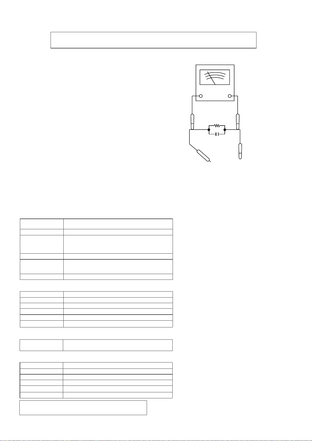
3. To be sure that no shock hazard exists, check for leakage
current in the following manner.
* Plug the AC line cord directly into a 120 volt AC outlet.
* Using two clip leads, connect a 1.5k ohm, 10 watt resistor
paralleled by a 0.15µF capacitor in series with all exposed
metal cabinet parts and a known earth ground, such as
conduit or electrical ground connected to earth ground.
* Use a VTVM or VOM with 1000 ohm per volt, or higher,
sensitivity to measure the AC voltage drop across the
resistor (See diagram).
* Connect the resistor connection to all exposed metal parts
having a return path to the chassis (antenna, metal cabinet,
screw heads, knobs and control shafts, escutcheon, etc.)
and measure the AC voltage drop across the resistor.
IMPORTANT SERVICE NOTES (FOR U.S.A. ONLY)
All check must be repeated with the AC line cord plug connection
reversed.
Any reading of 0.3 volt RMS (this corresponds to 0.2 milliamp.
AC.) or more is excessive and indicates a potential shock
hazard which must be corrected before returning the audio
product to the owner.
SPECIFICATIONS
Specifications for this model are subject to change without
prior notice.
AC SCALE
VTVM
1.5k ohms
10W
0.15µF
TEST PROBE
TO EXPOSED
METAL PARTS
CONNECT TO
KNOWN EARTH
GROUND
■
Tape recorder
Frequency response
Signal/noise ratio
Wow and fiutter
Motor
Bias system
Erase system
50 - 14,000 Hz (Normal tape)
50 dB
0.25 % (WRMS)
DC 9 V electric governor
AC bias
Magnet erase
■
Compact disc player
Type
Signal readout
Audio channels
Filter
D/A converter
Wow and flutter
Compact disc
Non-contact, 3-beam semi-conductor laser pickup
2
8-time oversampling digital filter
1-bit D/A converter
Unmeasurable (less than 0.001% W. peak)
■
General
AC 120 V, 60 Hz
DC 9 V [“D” size (UM/SUM-1, R20 or HP-2) battery x 6]
11 W
3-1/8" (8 cm) full-range speaker x 2
5.5 lbs. (2.5 kg) without batteries
Power source
Power consumption
Output power
Speakers
Dimensions
Weight
FM; 87.5 - 108 MHz
AM; 530 - 1,720 kHz
■
Radio
Frequency range
FTC; 2.0 W min. RMS per channel into 4 ohms from 150
Hz to 20 kHz, with no more than 10 % total harmonic
distortion.
RMS; 2.3 W/CH (DC operation, 10 % T.H.D)
Width; 14-6/8" (376 mm)
Height; 5-7/8" (150 mm)
Depth; 9" (230 mm)
QT-CD180
– 3 –
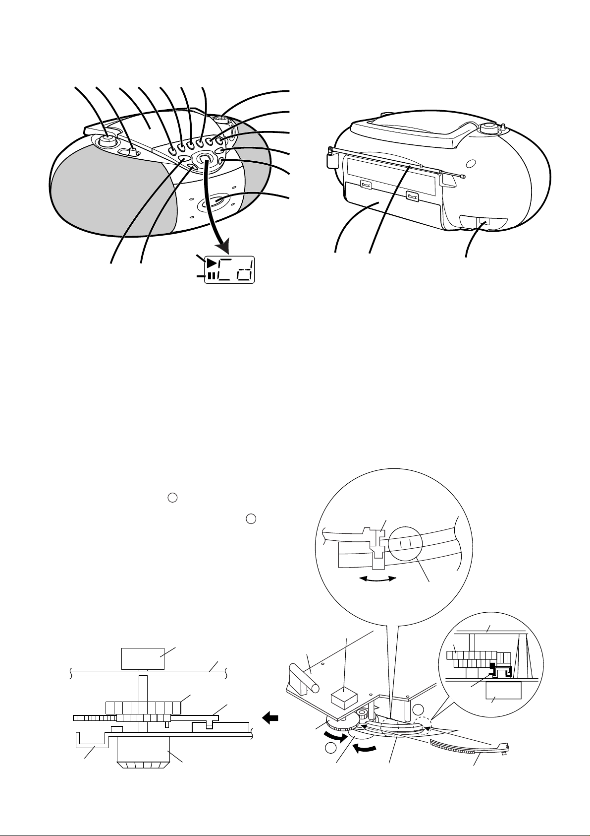
NAMES OF P ARTS
FITTING OF DIAL POINTER
Setting method of the dial pointer
1. Remove the front cabinet. (Refer to Fig.5-2 on page 5,
"Disassembly method".)
2. Remove the dial pointer.
3. Insert the dial pointer from A of the top cabinet so that it
engages with the drum gear.
4. Fully turn the drum in the opposite direction of B and set
it to the FL marks.
5. Reassemble the front cabinet.
Figure 3-1
Drum
Drum
Dial
Pointer
Dial
Pointer
Tuning Knob
Tuning Knob
Main PWB
Main PWB
Main PWB
Top Cabinet
Top Cabinet
Variable
Capacitor
Variable
Capacitor
A
B
Drum
Dial
Pointer
Tuning Knob
FL Mark
Dial Pointer
FH
FL
1234567
8
9
10
11
12
13
14 15
16
17
10. (TAPE) Record Button
11. (CD) Play/Pause Button
12. (CD) Track Up/Cue Button
13. Cassette Compartment
14. (CD) Stop Button
15. (CD) Track Down/Review
Button
16. (CD) Play Indicator
17. (CD) Pause Indicator
01. Volume Control
02. Function Switch
03. CD Compartment
04. (TAPE) Pause Button
05. (TAPE) Stop/Eject Button
06. (TAPE) Fast Forward Button
07. (TAPE) Rewind Button
08. Tuning Control
09. (TAPE) Play Button
18
19
20
18. Battery Compartment
19. FM Telescopic Rod Antenna
20. AC Power input Socket
QT-CD180
– 4 –
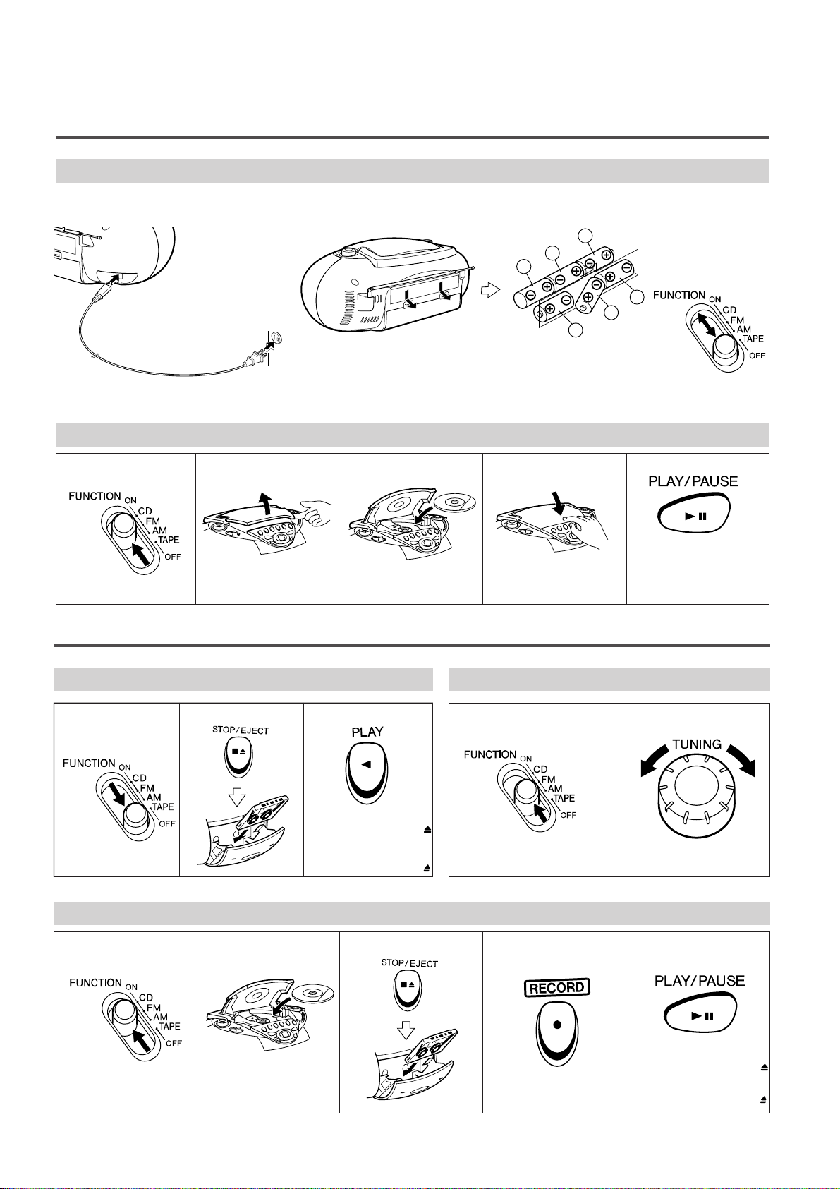
OPERATION MANUAL
Quick Guide /
Guía rápida
■ Operation with AC power
■
Funccionamiento con corriente alterna
■ Operation with batteries
■
Funccionamiento con pilas
To an AC outlet
A un tomacorriente de CA
T o AC INPUT
A la toma AC INPUT
AC 120 V, 60 Hz
120 V de CA, 60 Hz
● 6 “D” size batteries (UM/SUM-1, R20, HP-2 or similar)
● Batteries are not included.
●
6 pilas del tamaño “D” (UM/SUM-1, R20, HP-2 o similares)
●
Las pians no están incluidas.
5
4
6
1
3
2
■ Turning the power
ON and OFF
■
Conexión (ON) y
desconexión (OFF)
de la alimentación
● Label side up.
●
Con el lado de la etiqueta
encarada hacia arriba.
To stop playback
Press the STOP ■ button.
Para detener la
reproducción
Pulse el botón STOP
■
.
123 45
1
Preparation for use /
Preparación para su uso
2
Listening to a CD /
Audictión de CD
123
To stop playback
Press the STOP/EJECT ■
button.
Para detener la
reproducción
Pulse el botón STOP/EJECT
■
.
12
12
● Load the disc to be
recorded.
●
Introduzca el disco que
va a grabar.
To stop recording
Press the STOP/EJECT ■
button.
Para detener la grabación
Pulse el botón STOP/EJECT
■
.
3
Listening to a tape /
Audictión de una cinta
4
Listening to the radio /
Audic
tión de la radio
5
Recording from a CD /
Grabaciones de CD
4
3
5
QT-CD180
– 5 –
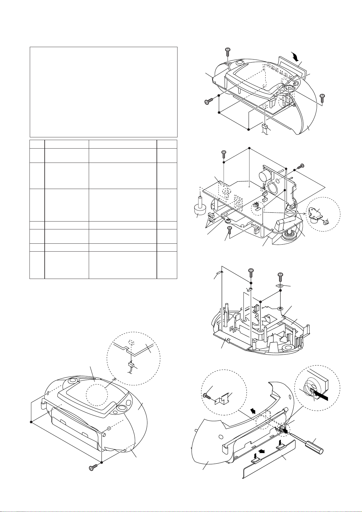
1 Rear Cabinet 1. Screw ................... (A1) x4 5-1
2. Socket .................. (A2) x1
2 Front Cabinet 1. Open the cassette holder 5-2
2. Socket .................. (B1) x1
3. Screw ................... (B2) x4
4. Screw ................... (B3) x2
3 Main PWB 1. Knob..................... (C1) x1 5-3
(With CD Control 2. Socket .................. (C2) x3
PWB) 3. Screw ................... (C3) x5
(Note) 4. Screw ................... (C4) x1
5. Socket .................. (C5) x1
4 Tape Mechanism 1. Screw ................... (D1) x2 5-3
5 CD Control PWB 1. Screw ................... (E1) x2 5-4
(With Main PWB) 2. Bracket................. (E2) x2
6 CD Mechanism 1. Screw ................... (F1) x3 5-4
7 Power PWB 1. Battery Lid............(G1) x1 5-5
2. Screw ................... (G2) x1
3. Bracket ................. (G3) x1
4. Hook..................... (G4) x1
DISASSEMBLY
Caution on Disassembly
Follow the below-mentioned notes when disassembling the
unit and reassembling it, to keep it safe and ensure excellent
performance:
1. Take cassette tape and compact disc out of the unit.
2. Be sure to remove the power supply plug from the wall
outlet before starting to disassemble the unit.
3. Take off nylon bands or wire holders where they need
to be removed when disassembling the unit. After
servicing the unit, be sure to rearrange the leads
where they were before disassembling.
4. Take sufficient care on static electricity of integrated
circuits and other circuits when servicing.
STEP REMOVAL PROCEDURE FIGURE
Figure 5-3
Figure 5-1
Figure 5-2
Figure 5-5
Figure 5-4
Note:
After removing the connector for the optical pickup from the
connector, wrap the conductive aluminium foil around the
front end of connector remove to protect the optical pickup
from electrostatic damage.
(G2)x1
ø3x10mm
Rear Cabinet
Power PWB
Driver
(G4)x1
(G1)x1
(G3)x1
Front Cabinet
Rear Cabinet
Top Cabinet
Main
PWB
(A2)x1
(A1)x4
ø3x14mm
(B3)x1
ø3x8mm
(B2)x4
ø3x10mm
(B3)x1
ø3x8mm
Tape
Mechanism
Front Cabinet
Main
PWB
Open
Cassette
Holder
(B1)x1
(F1)x3
ø2.5x10mm
CD Mechanism
CD Control
PWB
Top Cabinet
PWB
Washer x3
(E1)x2
ø3x10mm
(E2)x1
(E2)x1
(C3)x5
ø3x10mm
(D1)x2
ø3x8mm
(C4)x1
ø2.5x10mm
(C5)x1
(C2)x3
(C1)x1
Volume
PWB
Tape
Mechanism
CD Mechanism
CD Motor
PWB
Main PWB
Top Cabinet
QT-CD180
– 6 –
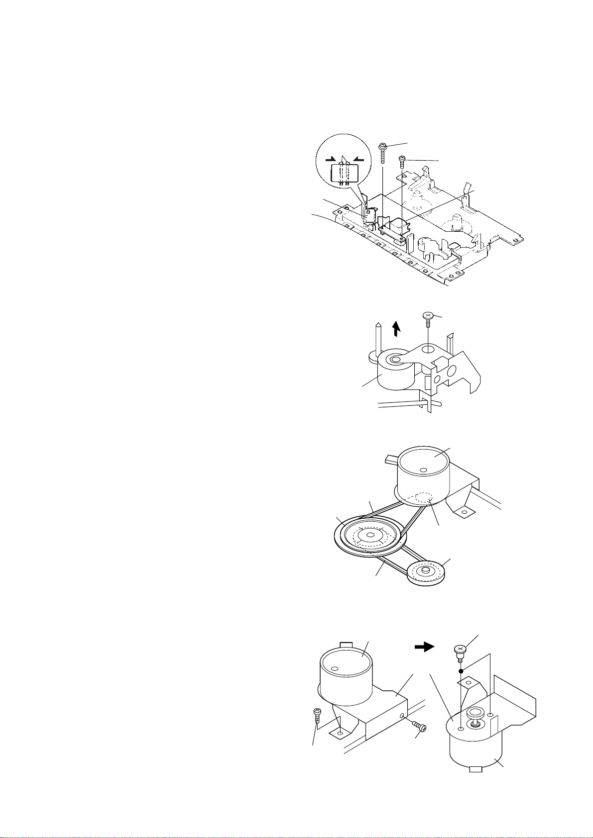
TAPE MECHANISM SECTION
Perform steps 1 to 4 of the disassembly method to remove the
tape mechanism. (See page 5.)
How to remove the record / playback and erase
heads (See Fig. 6-1.)
1. Remove the screws (A1) x 2 pcs., to remove the record/
playback head.
2. Remove the hooks (A2) x 2 pcs., toward the center
position as shown in Fig. 6-1. and then extract the erase
head upward.
Note:
After replacing the heads and performing the azimuth
adjustment, be sure to apply screwlock.
How to remove the pinch roller (See Fig. 6-2.)
1. Remove the screw (B1) x 1 pc., and remove the pinch roller
upwards.
How to remove the belts (See Fig. 6-3.)
1. Remove the main belt (C1) x 1 pc., from the motor
pulley.
2. Remove the FF/REW belt (C2) x 1 pc., from the REW/FF
roller.
3. Put on the belts in the reverse order of removal.
Note:
When putting on the belt, ascertain that the belt is not twisted,
and clean it.
How to remove the motor
(See Fig. 6-4.)
1. Remove the main belt. (See Fig. 6-3.)
2. Remove the screws (D1) x 2 pcs., to remove the motor
bracket.
3. Remove the screws (D2) x 2 pcs., to remove the motor.
Note:
When mounting the motor, pay attention to the motor bracket
angle.
Figure 6-1
Figure 6-2
Figure 6-3
Figure 6-4
(A1) x1
ø2x7mm
(A1) x1
ø2x3mm
Record/Playback
Head
Erase Head
Hook
(A2)x2
REMOVING AND REINSTALLING THE MAIN PARTS
Pinch Roller
(B1) x1
ø1.5x2.5mm
Motor Bracket
Motor
Motor
(D2)x2
Special
Screw
(D1) x1
ø2.5x4mm
(D1) x1
ø2.5x4mm
Motor
REW/FF
Roller
Flywheel
FF/REW Belt
(C2)x1
Main Belt
(C1)x1
Motor Pulley
QT-CD180
– 7 –
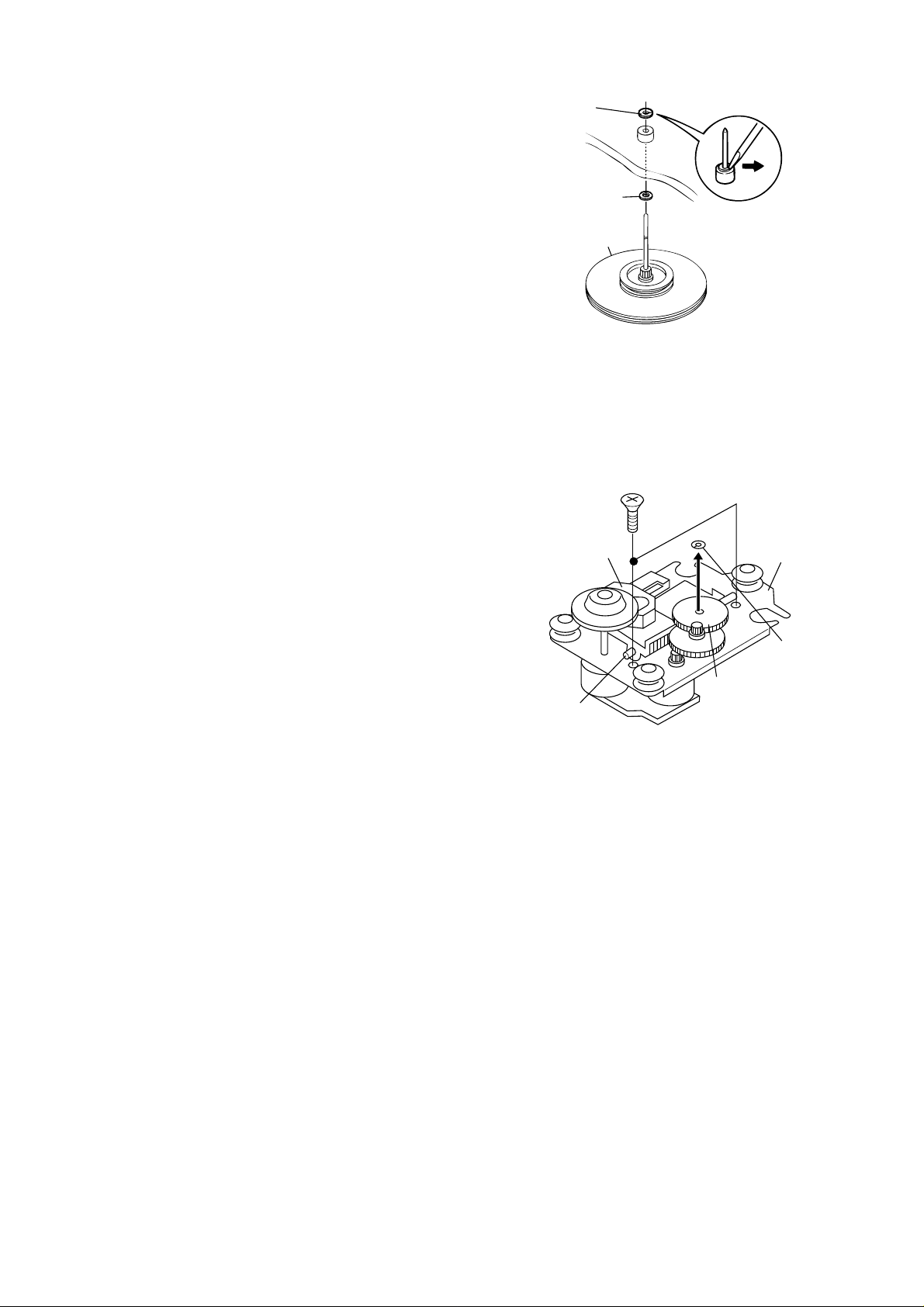
CD MECHANISM SECTION
Perform steps 1 to 6 of the disassembly method to remove the
CD mechanism. (See page 5.)
How to remove the pickup (See Fig. 7-2.)
1. Remove the screws (A1) x 2 pcs., to remove the shaft
(A2) x1 pc.
2. Remove the stop washer (A3) x1 pc., to remove the gear
(A4) x 1 pc.
3. Remove the pickup.
Stop
Washer
(A3) x1
CD
Mechanism
Gear
(A4) x1
Shaft
(A2) x1
Pickup
(A1) x2
ø2.6 x6mm
Figure 7-2
Figure 7-1
(E1) x 1
Stop Washer
Washer
Flywheel
How to remove the flywheel (See Fig. 7-1.)
1. Remove the belt. (See Fig. 6-3.)
2. Remove the stop washer (E1) x 1 pc., with a small
precision screwdriver to extract the flywheel from the
capstan metal.
Note:
When the stop washer is deformed or damaged, replace it
with a new one.
How to reinstall the parts
Install each part in the reverse order of the removal with care.
Note:
After removing the connector for the optical pickup from the
connector, wrap the conductive aluminium foil around the
front end of connector remove to protect the optical pickup
from electrostatic damage.
QT-CD180
– 8 –
MECHANISM SECTION
• Driving Force Check
PLAY: TW-2412 Over 80 g
Torque Meter
Specified Value
• Torque Check
Torque Meter
Specified Value
Play: TW-2111 30 to 60 g.cm
Fast Forward: TW-2231 55 to 140 g.cm
Rewind: TW-2231 55 to 140 g.cm
• Tape Speed
MTT-111 Variable 3,000 ± 90 Hz Output: Speaker
resistor in Terminal
motor. (M601) (CNP201 Load
resistance: 4 ohms)
Instrument
Connection
Specified
Value
Test
Tape
TAPE SECTION
Position of each switch or control
Volume control Max
Function switch Tape/Power Off
• Bias Oscillation
Adjustment Point
• Playback Amplifier Sensitivity Check
Instrument Connection
Test Tape
MTT-118 1.1 V ± 3 dB Speaker Terminal
(Load resistance: 4 ohms)
Specified Value
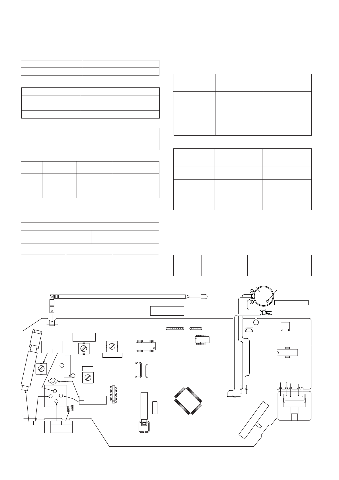
ADJUSTMENT
TUNER SECTION
fL: Low-range frequency
fH: High-range frequency
• FM IF/RF
FM Detection T2
FM fL: L2
Band Coverage fH: TC2
FM Tracking fL: 88.0 MHz: L1
fH: 108.0 MHz: TC1
Test Stage
Specified
Value/Adjusting
Point
Instrument
Connection
Input: Pin 1 of IC1
Output: Pin 18 of IC1
Input: Antenna
Output: Speaker
Terminal (CNP201
Load resistance: 4
ohms)
• AM IF/RF
AM IF T3 Input: Antenna
Output: Pin 18 of IC1
AM fL: L4 Input: Antenna
Band Coverage fH: TC4 Output: Speaker
AM Tracking fL: 600 kHz: L3 Terminal (CNP201
fH: 1,400 kHz: TC3 Load resistance: 4
ohms)
Test Stage
Specified
Value/Adjusting
Point
Instrument
Connection
Figure 8 ADJUSTMENT POINTS
• Head Azimuth
Torque Meter
Specified Value
MTT-114 Output: Speaker Terminal
(CNP201 Load resistance: 4 ohms)
Adjusting
Point
Specified Value
Instrument
Connection
L301 80 kHz ± 6 kHz Pin 1 of CNP101
M601
TAPE MOTOR
SW601
TAPE MAIN
TAPE MECHANISM
Variable resistor
in motor
VR201
SW201
CNP101
SW102
L1
L4
L2
IC1
T3
IC101
BI803
IC201
CNP602
BI802
BI801
L301
T2
1
1
TC4
TC2
TC1
TC3
FM ROD ANTENNA
MAIN PWB
1
13
18
AM BAND
COVERAGE
fL
fH
AM IF
FM
DETECTION
12
24
BIAS OSC.
AM
TRACKING
fL
fH
L3
AM BAR
ANTENNA
1
12
11
2
2
3
4
1
23
2
FM BAND
COVERAGE
L3
IC802
IC803
1
14
15
IC801
1
12
13
24
CNP201
28
fH
fL
FM
TRACKING
fH
fL

QT-CD180
– 9 –
CD SECTION
Since this CD system incorporates the following automatic adjustment function, when the pickup is replaced, it is not necessary
to readjust it.
Since this CD unit does not need adjustment, the combination of PWB and laser pickup unit is not restricted.
TEST MODE
While holding down the "Stop" and "Up" button at same time, move the FUNCTION switch to "CD".
Start
Note
1. When the CD LID switch is in the OFF position, (CD LID is open) the unit will be able to enter the test mode.
However, can use the "UP/CUE" and "DOWN/REVIEW" button only.
2. You can only move the pickup.
3. The LCD display should be the same as it is for normal CD operations.
Operation
The use of the "UP/CUE" button will move the pickup to the outermost position.
The use of the "DOWN/REVIEW" button will move the pickup to the innermost position.
After connecting of the 10 kohm resistor between IC802 27 pin and GND and holding down the "Stop" and "Up"
button at same time, move the FUNCTION switch to "CD".
Start
Display
LCD MODE
1. Before the laser light up, CD LID switch (SW801) terminals have to be short with the solder.
Resistor of 330ohm is put from 27 pin of IC802, and you must connect it to GND of PWB. (Refer to PWB of Figure9-1.)
PREPARATION FOR LASER LIGHT UP
Figure 9-1
1. Remove the front cabinet according to the disassembly method.
2. Short the TP of the Figure 9-1 to turn on the CD LID switch (SW810).
3. While holding down the "Stop" and "Up" button at same time, move the FUNCTION switch to "CD".
4. Open the CD LID and press the PLAY button. The laser lights up for a few seconds. (At this time, the pickup lens moves
up and down and adjusts the focus to check if there is a disc or not.)
LASER LIGHTING CONFIRMATION
TP
1
5
10
12
13
15
20
24
7
10
20
8
21
22
1
5
8
1
5
25
28
1
16
E
C
B
1234
C847
C844
C853
C846
C855
X801
C84
0
IC801
C820
C863
C829
R829
C819
R830
R806
R851
R852
C842
C839
C838
R824
R820
C841
C830
R805
C828
BI802
C804
C816
R802
C801
R804
C815
C802
BI801
Q801
C817
R801
C835
C834
R853
C807
IC802
R839
R862
R844
R846
C824
R861
CNP101
C843
R821
C825
R843
C823
R826
C827
R827
C826
C833
R828
FW806
C106
R106
SW102
IC803
BI803
805
1
5
10
15
20
25
30
31
35
40
45
50
51
55
60
65
70
75
80
81
85
90
95
100
A
B
C
D
H
G
F
E
SW102
RECORD/PLAYBACK
PLAY
REC.
1
10
330 ohm
Resistor
GND
27pin
MAIN
PWB-A1
OPEN/CLOSE
SW810
CD LID
SWITCH
BR
BR
GY
GY
GY
GY
GY
H
QT-CD180
– 10 –
1. In Power OFF state, set the Function switch to ON, keeping to be pressed the "Stop" and "Up" button at same time.
After CD initialize finish. The CD TEST mode is set, and the LCD indicate to the total tracks of the disc. Release the PLAY button.
The CD TEST mode is set when the LCD indicate to " 1".
Then cut the above circuit.
2. In above TEST mode state, press once the PLAY button.
The laser is light up when LCD indicate to "cd".
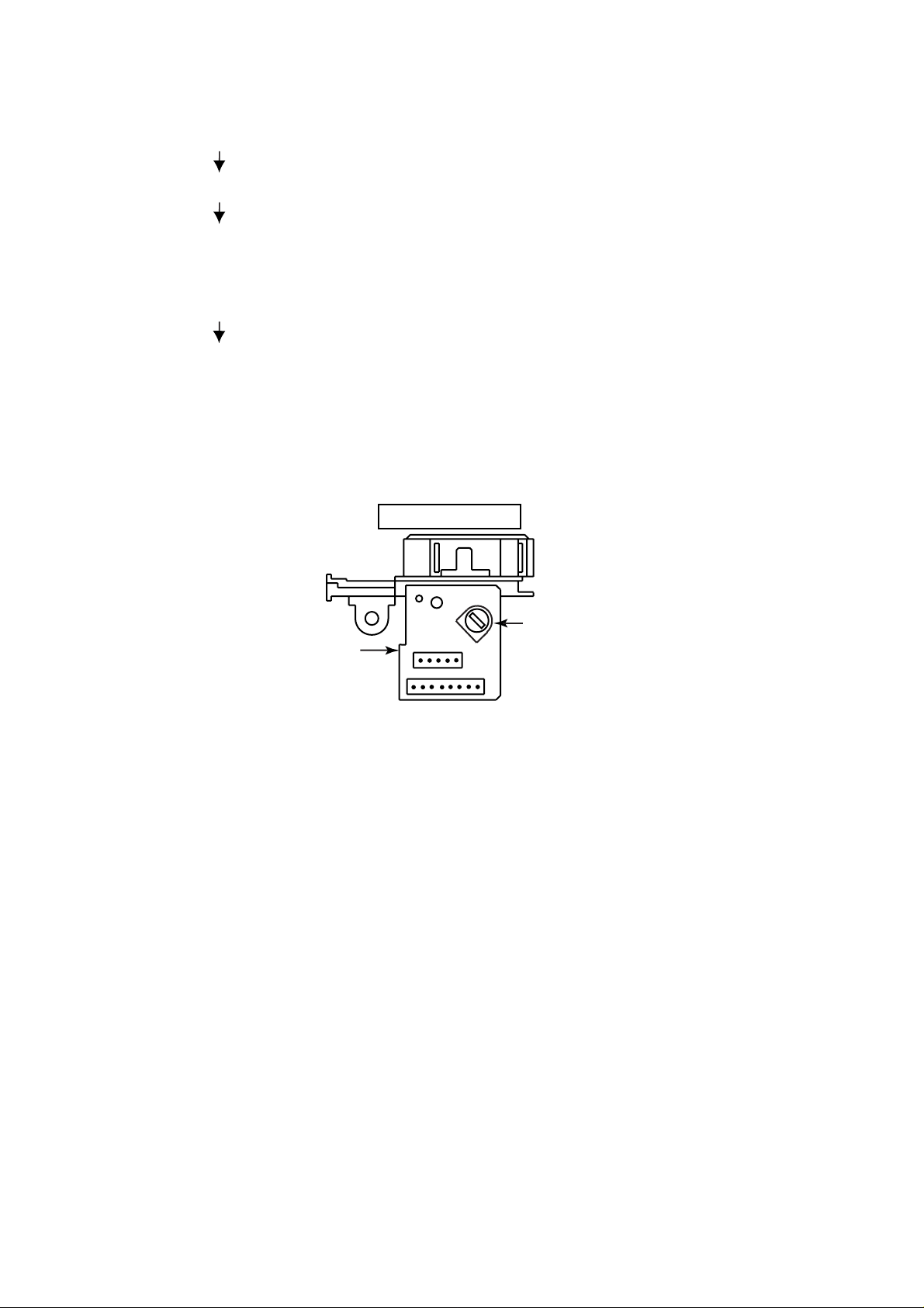
SETTING METHOD FOR LASER LIGHT UP
Figure 10
SETTING FOR MAXIMUM LASER POWER
1. In above laser light up state, adjust the variable resistor (VR1A) on pickup PWB to maximum laser power.
Maximum laser power : Rotate the variable resistor (VR1A) to clockwise.
Note :
The TEST mode is cleared by Power OFF.
PICKUP UNIT
Variable Resistor
VR1A
Pickup PWB
 Loading...