


|
|
QT-CD250H/W |
SERVICE MANUAL |
||
|
|
No. S3017QTCD250H |
|
QT-CD250H(S) |
|
|
QT-CD250W(S) |
|
|
• In the interests of user-safety the set should be restored to its |
|
|
original condition and only parts identical to those specified should |
|
|
be used. |
|
|
• Note for users in U.K. |
|
|
Recording and playback of any material may require consent |
|
Illustration: QT-CD250H |
which SHARP is unable to give. Please refer particularly to the |
|
|
provisions of Copyright Act 1956, the Dramatic and Musical |
|
|
Performers Protection Act 1956, the Performers Protection Acts |
|
|
1963 and 1972 and to any subsequent statutory enactments and |
|
|
orders. |
|
CONTENTS |
|
|
|
|
Page |
AC POWER SUPPLY CORD AND AC PLUG ADAPTOR (FOR QT-CD250W) ................................................................ |
1 |
|
SAFETY PRECAUTION FOR SERVICE MANUAL ........................................................................................... |
|
................ 2 |
IMPORTANT SERVICE NOTES (QT-CD250H FOR U.K. ONLY) ............................................................................. |
....... 3 |
|
VOLTAGE SELECTION (QT-CD250W ONLY) ............................................................................................. |
|
..................... 3 |
SPECIFICATIONS ................................................................................................................. |
............................................ |
3 |
NAMES OF PARTS ................................................................................................................. |
.......................................... |
4 |
OPERATION MANUAL ............................................................................................................... |
....................................... |
5 |
DISASSEMBLY .................................................................................................................... |
.............................................. |
8 |
REMOVING AND REINSTALLING THE MAIN PARTS ....................................................................................... |
|
.............. 8 |
ADJUSTMENT ..................................................................................................................... |
............................................ |
10 |
SCHEMATIC DIAGRAM .............................................................................................................. |
.................................... |
14 |
WIRING SIDE OF P.W.BOARD ....................................................................................................... |
................................ |
16 |
NOTES ON SCHEMATIC DIAGRAM ..................................................................................................... |
|
......................... 18 |
TYPES OF TRANSISTOR ............................................................................................................ |
................................... |
18 |
WAVEFORMS OF CD CIRCUIT ........................................................................................................ |
.............................. |
19 |
TROUBLESHOOTING (CD SECTION) ................................................................................................... |
|
........................ 20 |
FUNCTION TABLE OF IC ........................................................................................................... |
..................................... |
24 |
PARTS GUIDE/EXPLODED VIEW |
|
|
PACKING METHOD (QT-CD250H FOR U.K. ONLY) |
|
|
AC POWER SUPPLY CORD AND AC PLUG ADAPTOR (FOR QT-CD250W) |
||
QACCA0001SJ00 |
QPLGA0253AFZZ |
|
QACCB0001SJ00
QACCE0001SJZZ |
|
|
|
QPLGA0250AFZZ |
|
|
|
|
|
|
|
|
|
|
|
|
|
|
|
|
|
|
|
|
|
|
|
|
|
|
|
|
|
|
|
|
|
|
|
|
|
SHARP CORPORATION |
This document has been published to be used |
for after sales service only. |
|
– 1 – |
The contents are subject to change without notice. |
|

QT-CD250H/W
SAFETY PRECAUTION FOR SERVICE MANUAL
Precaution to be taken when replacing and servicing the Laser Pickup.
The AEL (Accessible Emission Level) of Laser Power Output for this model is specified to be lower than Class I Requirements. However, the following precautions must be observed during servicing to protect your eyes against exposure to the Laser beam.
(1)When the cabinet has been removed, the power is turned on without a compact disc, and the Pickup is on a position outer than the lead-in position, the Laser will light for several seconds to detect a disc. Do not look into the Pickup Lens.
(2)The Laser Power Output of the Pickup inside the unit and replacement service parts have already been adjusted prior to shipping.
(3)No adjustment to the Laser Power should be attempted when replacing or servicing the Pickup.
(4)Under no circumstances look directly into the Pickup Lens at any time.
(5)CAUTION - Use of controls or adjustments, or performance of procedures other than those specified herein may result in hazardous radiation exposure.
VAROITUS! LAITTEEN KéYTTéMINEN MUULLA KUIN TéSSé KéYTTôOHJEESSA MAINITULLA TAVALLA SAATTAA ALTISTAA KéYTTéJéN TURVALLISUUSLUOKAN 1 YLITTéVéLLE NéKYMéTTôMéLLE LASERSéTEILYLLE.
VARNING - OM APPARATEN ANVéNDS Pè ANNAT SéTT éN I DENNA BRUKSANVISNING SPECIFICERAS. KAN ANVéNDAREN UTSéTTAS FôR OSYNLIG LASERSTRèLNING, SOM ôVERSKRIDER GRéNSEN FôR LASERKLASS 1.
CAUTION-INVISIBLE LASER RADIATION WHEN OPEN. DO NOT STARE INTO BEAM OR VIEW DIRECTLY WITH OPTICAL INSTRUMENTS.
VARNING-OSYNLIG LASERSTRALNING NAR DENNA DEL AR OPPNAD. STIRRA EJ IN I STRALEN OCH BETRAKTA EJ STRALEN MED OPTISKA INSTRUMENT.
ADVERSEL-USYNLIG LASERSTRALING VED ABNING. SE IKKE IND I STRALEN-HELLER IKKE MED OPTISKE INSTRUMENTER.
VARO! AVATTAESSA OLET ALTTIINA NAKYMATON LASERSATEILYLLE. ALA TUIJOTA SATEESEEN ALAKA KATSO SITA OPTISEN LAITTEEN LAPI.
VARNING-OSYNLIG LASERSTRALNING NAR DENNA DEL AR OPPNAD. STIRRA EJ IN I STRALEN OCH BETRAKTA EJ STRALEN GENOM OPTISKT INSTRUMENT.
ADVERSEL-USYNLIG LASERSTRALING NAR DEKSEL APNES. STIRR IKKE INN I STRALEN ELLER SE DIREKTE MED OPTISKE INSTRUMENTER.
Laser Diode Properties
Material: GaAIAs
Wavelength: 780 nm
Emission Duration: continuous
Laser Output: max. 0.6 mW
LASER KLASSE 1
LUOKAN 1 LASERLAITE
KLASS 1 LASERAPPARAT
QT-CD250H for Europe |
|
QT-CD250H for Europe |
|
|
|
|
|
CAUTION |
Laser Diode Properties |
||
|
|
|
Material: GaAIAs |
|
|
|
Wavelength: 780 nm |
|
|
|
Emission Duration: continuous |
|
|
|
Laser Output: max. 0.6 mW |
|
|
|
CAUTION-INVISIBLE LASER RADIATION WHEN OPEN. DO NOT STARE INTO |
|
|
|
BEAM OR VIEW DIRECTLY WITH OPTICAL INSTRUMENTS. |
|
|
|
VARNING-OSYNLIG LASERSTRALNING NAR DENNA DEL AR OPPNAD. STIRRA |
|
|
|
EJ IN I STRALEN OCH BETRAKTA EJ STRALEN MED OPTISKA INSTRUMENT. |
|
|
|
ADVERSEL-USYNLIG LASERSTRALING VED ABNING. SE IKKE IND I |
● |
This Portable CD Stereo System is classified |
STRALEN-HELLER IKKE MED OPTISKE INSTRUMENTER. |
|
VARO! AVATTAESSA OLET ALTTIINA NAKYMATON LASERSATEILYLLE. |
|||
|
as a CLASS 1 LASER product. |
|
ALA TUIJOTA SATEESEEN ALAKA KATSO SITA OPTISEN LAITTEEN LAPI. |
|
|
VARNING-OSYNLIG LASERSTRALNING NAR DENNA DEL AR OPPNAD. |
|
● |
The CLASS 1 LASER PRODUCT label is lo- |
STIRRA EJ IN I STRALEN OCH BETRAKTA EJ STRALEN GENOM OPTISKT |
|
INSTRUMENT. |
|||
|
cated on the rear cover. |
|
ADVERSEL-USYNLIG LASERSTRALING NAR DEKSEL APNES. STIRR IKKE |
|
|
INN I STRALEN ELLER SE DIREKTE MED OPTISKE INSTRUMENTER. |
|
● Use of controls, adjustments or performance of procedures other than those specified herein may result in hazardous radiation exposure.
As the laser beam used in this compact disc
QT-CD250H for U.K. player is harmful to the eyes, do not attempt to disassemble the cabinet. Refer servicing to
qualified personnel only.
QT-CD250H for Australia/New Zealand/Philippines/QT-CD250W
– 2 –
QT-CD250H/W
FOR A COMPLETE DESCRIPTION OF THE OPERATION OF THIS UNIT, PLEASE REFER TO THE OPERATION MANUAL.
IMPORTANT SERVICE NOTES (QT-CD250H FOR U.K. ONLY)
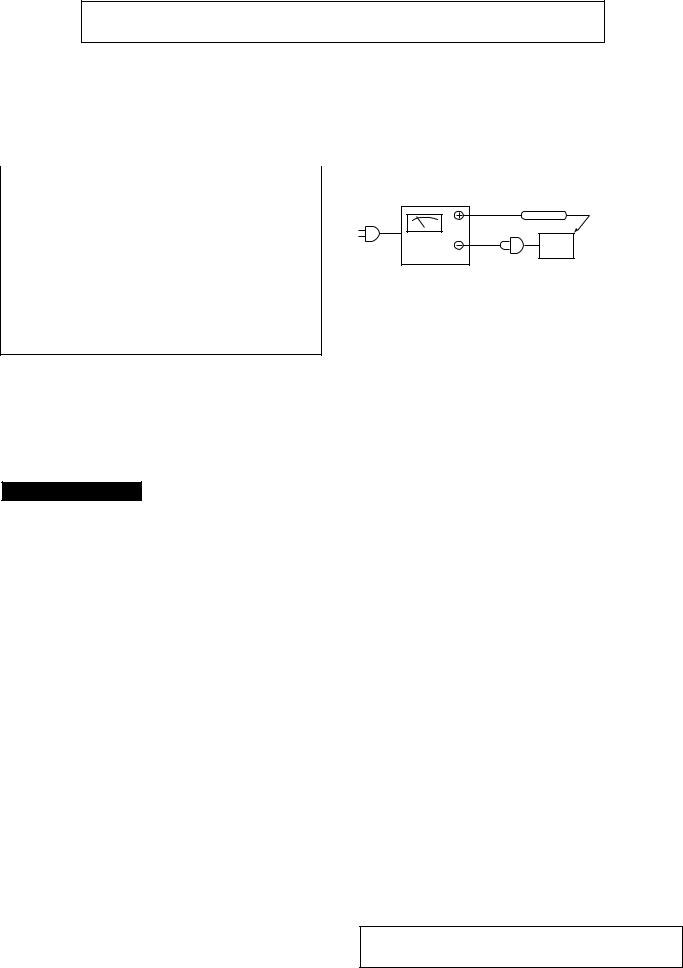
Before returning the unit to the customer after completion of a repair or adjustment it is necessary for the following withstand voltage test to be applied to ensure the unit is safe for the customer to use.
Setting of Withstanding Voltage Tester and set.
Set name |
Set value |
|
|
Withstanding Voltage Tester |
|
|
|
Test voltage |
4,240 VPEAK |
|
3,000 VRMS |
Set time |
6 secs |
Set current (Cutoff current) |
4 mA |
|
|
Unit |
|
|
|
Judgment |
|
|
|
OK: The “GOOD” lamp lights. |
|
NG: The “NG” lamp lights and the buzzor sounds.
WITHSTANDING
VOLTAGE TESTER
PROBE
AC
OUT
UNIT
SHORT-CIRCUT |
CONNECT THE PROBE |
AC POWER |
TO GND OF CHASSIS |
SUPPLY CORD |
SCREW TERMINAL |
VOLTAGE SELECTION (QT-CD250W ONLY)
The voltage selector is located on the AC voltage selector box. If adjustment is necessary, use a screwdriver in order to turn the selector in either direction unitil the correct voltage figure is displayed in the window next the adjustment screw.
SPECIFICATIONS
QT-CD250H/W
● General
Power source: (QT-CD250H for U.K./Europe)
Power source: (QT-CD250H for Australia/
New Zealand/ Philippines)
Power source: (QT-CD250W)
Power consumption: (QT-CD250H)
Power consumption: (QT-CD250W)
AC 230-240 V, 50 Hz
DC 9 V ["D" size (UM/SUM-1, R20 or HP-2) battery × 6]
DC 4.5 V ["AA" size (UM/SUM-3, R6 or HP-7) battery × 3 for backup memory]
●For customers in Australia and New Zealand;
AC 230-240 V, 50 Hz
● For customers in Philippines; AC 220 V, 60 Hz
DC 9 V ["D" size (UM/SUM-1, R20 or HP-2) battery × 6]
DC 4.5 V ["AA" size (UM/SUM-3, R6 or HP-7) battery × 3 for backup memory]
AC 110-127/220-240 V, 50/60 Hz DC 9 V ["D" size (UM/SUM-1, R20 or HP-2) battery × 6]
DC 4.5 V ["AA" size (UM/SUM-3, R6 or HP-7) battery × 3 for backup memory]
8 W
10 W
Output power: (QT-CD250H for Europe)
Output power: (QT-CD250H for U.K./Australia/ New Zealand/ Philippines/ OT-CD250W)
Speakers:
Output terminals: Dimensions:
Weight:
RMS; 4.6 W (2.3 W + 2.3 W) (DC operation, DIN 45 324) MPO; 8.4 W (4.2 W + 4.2 W) (AC operation, DIN 45 324)
RMS; 4.6 W (2.3 W + 2.3 W) (DC operation, 10 % T.H.D.) MPO; 8.4 W (4.2 W + 4.2 W) (AC operation, 10 % T.H.D.)
10 cm (4") full-range speaker x 2
Headphones; 16-50 ohms (recommended; 32 ohms) Width; 400 mm (15-3/4")
Height; 158 mm (6-1/4") Depth; 212 mm (8-3/8") 2.7 kg (6.0 lbs.)
without batteries
● Compact disc player
Type: |
Compact disc |
Signal |
Non-contact, 3-beam semi- |
readout: |
conductor laser pickup |
Audio |
|
channels: |
2 |
Filter: |
8-times oversampling |
|
digital filter |
D/A converter: |
1-bit D/A converter |
Wow and |
Unmeasurable |
flutter: |
(less than 0.001% W. peak) |
● Radio |
|
Frequency |
FM; 87.5 - 108 MHz |
range: |
AM; 522 - 1,620 kHz |
(QT-CD250H) |
|
● Radio |
|
Frequency |
FM; 88 - 108 MHz |
range: |
AM; 531 - 1,602 kHz |
(QT-CD250W) |
|
● Tape recorder |
|
Frequency |
|
response: |
50 - 14,000 Hz |
|
(Normal tape) |
Signal/noise |
|
ratio: |
50 dB |
Wow and |
|
flutter: |
0.25 % (WRMS) |
(QT-CD250H for |
|
U.K./Australia/ |
|
New Zealand/ |
|
Philippines/ |
|
QT-CD250W) |
|
Wow and |
|
flutter: |
0.3 % (DIN 45 511) |
(QT-CD250H for |
|
Europe) |
|
Motor: |
DC 9 V electric governor |
Bias system: |
AC bias |
Erase |
|
system: |
Magnet erase |
Specifications for this model are subject to change without prior notice.
– 3 –

QT-CD250H/W
NAMES OF PARTS
Illustration: QT-CD250W
1 |
2 |
3 |
4 |
5 |
6 |
7 |
8 |
9 |
10 |
|
|
|
|
|
|
|
|
11 |
|
|
|
|
|
|
|
14 |
|
|
|
|
|
|
|
|
15 |
12 |
|
|
|
|
16 |
13 |
|
|
|
|
|
|
|
|
|
17 |
|
|
|
|
|
|
|
18 |
|
|
|
|
|
19 |
20 21 |
22 |
23 |
24 |
25 |
26 27 |
28 29 |
|
VOLTAGE |
30 |
SELECTOR |
AC |
|
|
220V - 240V |
|
31 |
|
AC |
|
110V - 127V |
32 |
36 |
|
37 |
||
|
||
33 |
38 |
|
34 |
39 |
|
35 |
40 |
1. |
(TAPE) Record Button |
15. |
(CD) Track Up/Cue Button |
30. Backup Memory Battery |
|
2. |
(TAPE) Play Button |
16. |
(TUNER) Preset Up Button |
|
Compartment |
3. |
(TAPE) Rewind Button |
(CD) Track Down/Review Button |
31. Voltage Selector (QT-CD250W Only) |
||
4. |
(TAPE) Fast Forward Button |
17. |
(TUNER) Preset Down Button |
32. |
(CD) Play/Pause Button |
5. |
(TAPE) Stop/Eject Button |
Volume Up/Down Buttons |
|
(TUNER) Tuning Up Button |
|
6. |
(TAPE) Pause Button |
18. |
Stand-by, On/Function Switch |
33. |
(CD) Track Down/Review Button |
7. |
Cassette Compartment |
19. |
(CD) Play Indicator |
|
(TUNER) Preset Down Button |
8. |
CD Compartment |
20. |
(CD) Repeat Indicator |
34. |
(CD) Stop Button |
9. |
CD Eject Button |
21. |
(CD) Pause Indicator |
35. |
(TUNER) Tuning Down Button |
10. |
(CD) Stop Button |
22. |
Extra Bass Indicator |
(CD) Repeat Button |
|
11. |
(TUNER) Tuning Down Button |
23. |
(TUNER) Memory Indicator |
36. |
(TUNER) Band Selector Button |
(CD) Repeat Button |
24. |
(TUNER) FM Stereo Mode Indicator |
(TUNER) Memory Button |
||
|
(TUNER) Band Selector Button |
25. |
(TUNER) FM Stereo Indicator |
37. |
(TUNER) Clear Button |
12. |
(TUNER) Preset Memory Button |
26. Battery Compartment |
38. |
(CD) Track Up/Cue Button |
|
13. |
Extra Bass Button |
27. FM Telescopic Rod Aerial |
39. |
(TUNER) Preset Up Button |
|
14. |
(CD) Play/Pause Button |
28. Headphone Socket |
Extra Bass Button |
||
|
(TUNER) Tuning Up Button |
29. AC Power Input Socket |
40. |
Volume Up/Down Buttons |
|
REMOTE CONTROL
Remote sensor |
||
15 |
0.2 m - 6 m |
|
15 |
||
(8" - 20') |
||
|
||
Notes:
●Replace the batteries if the operating distance is reduced or if the operation becomes erratic.
●Periodically clean the transmitter LED on the remote control and the sensor on the main unit with a soft cloth.
●Exposing the sensor on the main unit to strong light may interfere with operation. Change the lighting or the direction of the unit.
●Keep the remote control away from moisture, excessive heat, shock, and vibrations.
– 4 –

– 5 –
1 Preparation for use
AC power lead x 1 |
● QT-CD250H for |
● QT-CD250H for |
● QT-CD250H for |
● QT-CD250H for |
customers in |
customers in |
customers in Europe |
customers in U.K. |
Australia and |
Philippines |
|
|
New Zealand |
|
|
● For QT-CD250W |
● For QT-CD250W ● For QT-CD250W |
■ AC power (For QT-CD250H)
(For U.K.)
AC 230 - 240 V, 50 Hz
To AC INPUT

 To an AC socket (For Australia/New Zealand)
AC 230 - 240 V, 50 Hz
(For Philippines) |
(For Europe) |
AC 220 V, 60 Hz |
AC 230 - 240 V, 50 Hz |
■ AC power (For QT-CD250W)
AC 110-127/220-240 V,
50/60 Hz
1
To AC INPUT |
2 |
VOLTAGE SELECTOR
AC
220V - 240V
AC |
To an AC socket |
110V - 127V |
|
To an AC socket
■ Battery power
2
3
1

 5 6
5 6
4
●6 “D” size batteries (UM/SUM-1, R20, HP-2 or similar)
●Batteries are not included.
■ Headphones |
■ Turning the power ON |
■ Volume control |
|
and to STAND-BY |
|
|
TUNER |
|
|
1 |
|
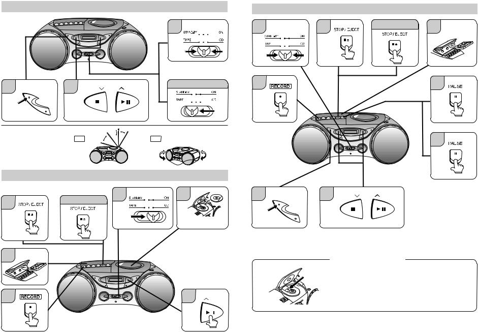
2 Listening to a CD |
|
|
|
1 |
2 |
3 |
4 |
|
TUNER |
|
|
Label side up.
To stop playback |
|
5 |
OPERATION |
|
|
||
STOP |
|
PLAY / PAUSE |
|
TUNING |
|
TUNING |
|
3 Listening to a tape |
|
|
MANUAL |
|
|
|
|
1 |
2 |
To stop playback |
|
|
|
|
TUNER
4 |
|
3 |
|
2 |
CD250H/WQT- |
|
|
– 6 –
4 Listening to the radio
1
TUNER
2 BAND |
3 |
STOP |
PLAY / PAUSE |
After use |
REPEAT |
|
TUNING |
TUNING |
|
|
|
|
||
|
|
|
|
TUNER |
|
|
Tune in to the desired station. |
|
|
■ Aerial adjustment |
|
FM |
|
AM |
|
|
|
||
5 Recording from CDs |
|
|
||
3 |
To stop recording |
1 |
2 |
|
|
|
|||
|
|
|
TUNER |
|
Label side up.
4
5 |
6 |
PLAY / PAUSE |
TUNING |
6 Recording from the radio |
|
|
|
1 |
4 |
To stop recording |
5 |
|
|
|
|
TUNER
7 |
6 |
8
2 |
BAND |
3 |
STOP |
PLAY / PAUSE |
|
REPEAT |
|
TUNING |
TUNING |
|
|
|
Tune in to the desired station.
CD pickup cleaning
● Do not touch the Laser pickup lens. If fingerprints or dust accumulate on the pickup, clean it using commercial cleaning disc (brush type.)
CD250H/W-QT
|
|
3 |
4 |
QT-CD250H/W
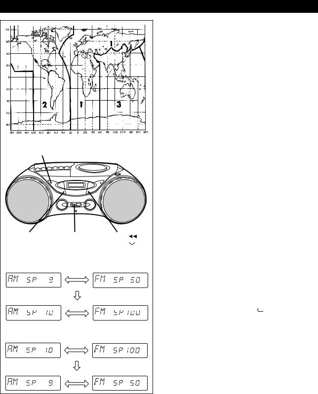
FM/AM INTERVAL (SPAN) (For QT-CD250W Only)
REPEAT |
|
|
BAND |
|
|
TUNER |
ON/STAND-BY |
REVIEW |
MEMORY |
(Function) |
PRESET |
[9 kHz 10 kHz] |
|
|
|
kHz |
kHz |
|
kHz |
kHz |
[10 kHz 9 kHz] |
|
|
|
kHz |
kHz |
|
kHz |
kHz |
The International Telecommunication Union (ITU) has established that member countries should maintain either a 10 kHz or a 9 kHz interval between broadcasting frequencies of any AM station. The illustration shows the 9 kHz interval zones (regions 1 and 3), and the 10 kHz interval zone (region 2).
This product is not equipped with a span selector. However, it will be adjusted to 9 kHz AM interval (50 kHz FM interval) when shipped from the factory.
Before using the unit, be sure to set it for the AM tuning interval (span) used in your area.
To check the tuning span currently selected:
1 Set the function switch to TUNER.
2 Press the REPEAT/BAND ( ) button to select the AM band.
●If “AM 531 kHz” is displayed, it means that the radio has been adjusted for a 9 kHz span.
If “AM 530 kHz” is displayed, it means that the radio has been adjusted for a 10 kHz span.
To change from a 9 kHz AM (50 kHz FM) interval to a 10 kHz AM (100 kHz FM) interval:
1 Set the function switch to TUNER.
2 Hold down the TUNER MEMORY button and the PRESET  button for at least 3 seconds. Release the buttons when “AM SP 9 kHz” and “FM SP 50 kHz” are displayed alternately.
3 Press the REPEAT/BAND ( ) button to select the “AM SP 10 kHz” and “FM SP 100 kHz” are displayed alternately.
4 Press the TUNER MEMORY button to set it.
●The unit will return back to the normal frequency display.
To return to a 9 kHz AM (50 kHz FM) interval:
1 Set the function switch to TUNER.
2 Hold down the TUNER MEMORY button and the PRESET  button for at least 3 seconds. Release the buttons when “AM SP 10 kHz” and “FM SP 100 kHz” are displayed alternately.
3 Press the REPEAT/BAND (  ) button to select the “AM SP 9 kHz” and “FM SP 50 kHz” are displayed alternately.
4 Press the TUNER MEMORY button to set it.
●The unit will return back to the normal frequency display.
Notes:
●If the backup memory batteries are not inserted and the power is disconnected, it will be automatically returned to a 9 kHz span.
If this happens, insert the backup memory batteries first and set the span again.
●When the span is switched, any stations that are memorised will be cancelled.
– 7 –

QT-CD250H/W
|
|
|
|
|
DISASSEMBLY |
(C3)x2 |
||
|
|
|
|
|
|
|
||
Caution on Disassembly |
|
|
|
|
||||
Follow the below-mentioned notes when disassembling the |
Switch PWB |
|||||||
unit and reassembling it, to keep it safe and ensure excellent |
SW651 |
|
||||||
(Voltage Selector) |
||||||||
performance: |
|
|
|
|
||||
|
|
|
|
QT-CD250W Only |
||||
1. Take cassette tape and compact disc out of the unit. |
Power Transformer |
|||||||
2. Be sure to remove the power supply plug from the wall |
|
|
||||||
outlet before starting to disassemble the unit. |
|
|
(D2)x7 |
|||||
3. Take off nylon bands or wire holders where they need to |
|
ø3x12mm |
||||||
be removed when disassembling the unit. After servicing |
|
Main PWB |
||||||
the unit, be sure to rearrange the leads where they were |
|
|
||||||
before disassembling. |
|
|
|
|
|
|||
4. Take sufficient care on static electricity of integrated |
|
|
||||||
circuits and other circuits when servicing. |
|
|
|
|||||
STEP |
REMOVAL |
|
PROCEDURE |
FIGURE |
|
(B4)x2 |
||
|
Terminal |
|
||||||
|
|
|
|
|
|
|
||
1 |
Top Cabinet/ |
1. Screw |
(A1) x7 |
8-1 |
PWB |
|
||
|
|
|||||||
|
Front Cabinet |
2. Socket .................. |
(A2) x1 |
|
|
|
||
|
|
3. |
Screw ................... |
(A3) x1 |
|
|
|
|
2 |
Power PWB/ |
1. |
Screw ................... |
(B1) x2 |
8-2 |
(B2)x2 |
||
|
Terminal PWB |
2. Hook ..................... |
(B2) x2 |
|
Power PWB |
|||
|
|
3. |
Socket |
(B3) x1 |
|
|||
|
|
|
Power Transformer |
|||||
|
|
4. |
Hook ..................... |
(B4) x2 |
|
|
|
|
3 |
Switch PWB |
1. Screw ................... |
(C1) x2 |
8-2 |
|
|
||
|
|
2. |
Socket .................. |
(C2) x1 |
|
(E1)x3 |
||
|
|
3. |
Hook ..................... |
(C3) x2 |
|
ø2.5x10mm |
||
|
|
4. |
Screw ................... |
(C4) x4 |
|
|
Washer |
|
4 |
Main PWB/ |
1. |
Socket |
(D1) x1 |
8-2 |
|
||
|
|
|||||||
|
CD Control PWB |
2. Screw ................... |
(D2) x7 |
|
|
(D5)x1 |
||
|
(Note) |
3. Screw ................... |
(D3) x1 |
|
|
|||
|
|
4. |
Solder ................... |
(D4) x3 |
|
|
|
|
|
|
5. |
Socket .................. |
(D5) x3 |
8-3 |
|
|
|
|
|
6. |
Screw ................... |
(D6) x6 |
|
|
|
|
|
|
7. |
Hook ..................... |
(D7) x2 |
|
|
|
|
5 |
CD Mechanism |
1. Screw ................... |
(E1) x3 |
8-3 |
|
|
||
6 |
Tape Mechanism |
1. Screw ................... |
(F1) x4 |
8-3 |
|
|
||
|
Top Cabinet |
|
|
|
|
|
|
|
SP202
R-CH
(C4)x4
ø3x10mm  (C1)x2
ø3x12mm
(D3)x1
ø2.5x8mm
CD Lid Switch
(C2)x1
(B3)x1

 (D1)x1
(D4)x3
Top Cabinet
AC Socket
(B1)x2 
ø3x12mm
Figure 8-2
CD Mechanism |
(F1)x4 |
|
ø3x10mm |
||
(D5)x2 |
||
|
Tape
Mechanism
|
(D6)x6 |
(A3)x1 |
ø3x8mm |
(D7)x2 |
|
ø3x10mm |
|
Front Cabinet |
Top Cabinet |
|
(A1)x4 |
Main |
|
PWB |
||
ø3x12mm |
||
(A2)x1 |
||
|
(A1)x3 |
ø3x12mm |
Figure 8-1
CD Control
PWB
Figure 8-3
REMOVING AND REINSTALLING THE MAIN PARTS
CD MECHANISM SECTION
Perform steps 1 to 5 of the disassembly method to remove the CD mechanism.
How to remove the pickup (See Fig. 8-4.)
1.Remove the screws (A1) x 2 pcs., to remove the shaft (A2) x1 pc.
2.Remove the stop washer (A3) x1 pc., to remove the gear (A4) x 1 pc.
3.Remove the pickup.
Note : (Figure 8-3 and Figure 8-4)
After removing the connector for the optical pickup from the connector, wrap the conductive aluminium foil around the front end of connector to protect the optical pickup from electrostatic damage.
– 8 –
(A1) x2 ø2.6 x6mm
Pickup |
CD |
Mechanism |
|
Stop |
|
Washer |
|
Gear (A3) x1 |
Shaft |
(A4) x1 |
(A2) x1 |
|
|
Figure 8-4 |
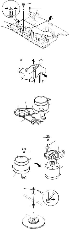
TAPE MECHANISM SECTION
Perform steps 1 to 6 of the disassembly method to remove the tape mechanism. (See page 8.)
How to remove the record / playback and erase heads (See Fig. 9-1.)
1.Remove the screws (A1) x 2 pcs., to remove the record/ playback head.
2.Remove the hooks (A2) x 2 pcs., toward the center position as shown in Fig. 9-1. and then extract the erase head
upward.
Note:
After replacing the heads and performing the azimuth adjustment, be sure to apply screwlock.
How to remove the pinch roller (See Fig. 9-2.)
1.Carefully bend the pinch roller pawl in the direction of the arrow <A>, and remove the pinch roller (B1) upwards.
How to remove the belts (See Fig. 9-3.)
1.Remove the main belt (C1) x 1 pc., from the motor pulley.
2.Remove the FF/REW belt (C2) x 1 pc., from the REW/FF roller.
3.Put on the belts in the reverse order of removal.
Note:
When putting on the belt, ascertain that the belt is not twisted, and clean it.
How to remove the motor (See Figs. 9-4.)
1.Remove the mainbelt.
2.Remove the screw (D1) x 1 pc., to remove the motor mount.
3.Remove the screws (D2) x 2 pcs., to remove the motor.
Note:
When mounting the motor, pay attention to the motor mounting angle.
How to remove the flywheel (See Fig. 9-5.)
1.Remove the belt.
2.Remove the stop washer (E1) x 1 pc., with a small precision screwdriver to extract the flywheel from the capstan metal.
Note:
When the stop washer is deformed or damaged, replace it with a new one.
QT-CD250H/W
Hook |
(A1) x1 |
(A2)x2 |
ø2x7mm |
(A1) x1 ø2x3mm
 Record/Playback
Head
Figure 9-1
|
<A> |
Pinch Roller |
Pinch Roller |
(B1)x1 |
Pawl |
Figure 9-2
Main Belt (C1)x1
Motor
Flywheel
FF/REW Belt |
REW/FF |
(C2)x1 |
Clutch Ass'y |
Motor
Motor Mount
Figure 9-3
(D2)x2 |
|
|
Special |
Motor |
|
Screw |
||
Mount |
||
|
||
(D1)x1 |
|
|
Special |
|
|
Screw |
|
|
|
Motor |
Figure 9-4
(E1) x 1 Stop Washer
Washer
Flywheel
How to reinstall the parts
Install each part in the reverse order of the removal with care.
Figure 9-5
– 9 –

QT-CD250H/W
ADJUSTMENT
MECHANISM SECTION
• Driving Force Check
Torque Meter |
Specified Value |
|
|
PLAY: TW-2412 |
Over 120 g |
|
|
• Torque Check
Torque Meter |
Specified Value |
|
|
Play: TW-2111 |
25 to 65 g.cm |
|
|
Fast Forward: TW-2231 |
60 to 130 g.cm |
|
|
Rewind: TW-2231 |
60 to 130 g.cm |
|
|
• Head Azimuth
Torque Meter |
Specified Value |
|
|
MTT-114 |
Output: Speaker Terminal |
|
(CNP201 Load resistance: 4 ohms) |
|
|
• Tape Speed
Test |
Adjusting |
Specified |
Instrument |
Tape |
Point |
Value |
Connection |
|
|
|
|
MTT-111 |
Variable |
3,000 ± 90 Hz |
Output: Speaker |
|
resistor in |
|
Teaminal |
|
motor. (M601) |
|
(CNP201 Load |
|
|
|
resistance: 4 ohms) |
|
|
|
|
TAPE SECTION
Position of each switch or control
Volume control |
Max |
Function switch |
Tape/Power Off |
X-BASS |
On |
|
|
• Bias Oscillation
Adjustment Point |
Specified Value |
Instrument |
|
|
Connection |
|
|
|
L301 |
82 kHz ± 6 kHz |
Pin 2 of CNP201 |
|
- 6 kHz |
|
|
|
|
∙ AM IF/RF (For QT-CD250H)
Signal generator: 400 Hz, 30%, AM modulated
Test Stage |
Frequency |
Frequency |
Setting/ |
Instrument |
|
|
Display |
Adjusting |
Connection |
|
|
|
Parts |
|
AM IF |
450 kHz |
1,620 kHz |
T3 |
*1 |
|
|
|
|
|
AM Band |
— |
522 kHz |
(fL): L4 |
*3 |
Coverage |
|
|
1.0 ±0.05V |
|
|
|
|
|
|
AM Tracking |
600 kHz |
603 kHz |
(fL): L3 |
*2 |
|
1,400 kHz |
1,404 kHz |
(fH): TC1 |
|
|
|
|
|
|
∙ AM IF/RF (For QT-CD250W)
Signal generator: 400 Hz, 30%, AM modulated
Test Stage |
Frequency |
Frequency |
Setting/ |
Instrument |
|
|
Display |
Adjusting |
Connection |
|
|
|
Parts |
|
AM IF |
450 kHz |
1,602 kHz |
T3 |
*1 |
|
|
(9kHz span) |
|
|
|
|
1,620 kHz |
|
|
|
|
(10kHz span) |
|
|
|
|
|
|
|
AM Band |
— |
531 kHz |
(fL): L4 |
*3 |
Coverage |
|
(9kHz span) |
1.0 ±0.05V |
|
|
|
|
|
|
AM Band |
— |
530 kHz |
(fL): L4 |
*3 |
Coverage |
|
(10kHz span) |
1.0 ±0.05V |
|
|
|
|
|
|
AM Tracking |
603 kHz |
603 kHz |
(fL): L3 |
*2 |
(9kHz span) |
1,404 kHz |
1,404 kHz |
(fH): TC1 |
|
|
|
|
|
|
AM Tracking |
600 kHz |
600 kHz |
(fL): L3 |
*2 |
(10kHz span) |
1,400 kHz |
1,400 kHz |
(fH): TC1 |
|
|
|
|
|
|
*1. |
Input: Antenna, |
Output: Pin 16 of IC1 |
|
*2. |
Input: Antenna, |
Output: Speaker Terminal |
|
*3. |
Input: Input is not connected, |
Output: TP1 |
|
|
|
|
CNP101 |
|
|
BIAS OSC. |
4 3 2 1 |
|
|
|
|
|
|
L301 |
SW102 |
• Playback Amplifier Sensitivity Check
11 1
IC101
12 2
Test Tape |
Specified Value |
Instrument Connection |
|
|
|
MTT-118 |
1.1 V ± 3 dB |
Speaker Terminal |
HPJ201 |
CNP602 |
CNP201 |
|
|
(Load resistance: 4 ohms) |
HEADPHONES |
3 |
3 2 1 |
|
|
|
2 |
|
|
|
|
|
|
1 |
|
TUNER SECTION |
|
|
MAIN PWB |
|
|
|
||||
fL: Low-range frequency |
|
|
|
|
|
|
||||
fH: High-range frequency |
|
|
|
|
|
|
||||
∙ FM RF |
|
|
|
|
|
|
AM |
|
||
Signal generator: 1 kHz, 75 kHz dev., FM modulated |
L3 |
|
||||||||
TRACKING fH |
||||||||||
|
|
|
|
|
|
AM BAR |
|
|
|
|
Test Stage Frequency |
Frequency |
Serring/ |
Instrument |
ANTENNA |
|
TC1 |
R7 |
|||
FM RF |
||||||||||
|
|
|
Display |
Adjusting |
Connection |
|
|
|||
|
|
|
|
L1 |
L4 |
|||||
|
|
|
|
Point |
|
|
||||
|
|
|
|
|
AM IF |
|
|
TP1 |
||
FM Band |
— |
|
87.5 MHz |
(fL): L2 |
*1 |
|
L2 |
|||
|
|
|
||||||||
|
T3 |
|
|
AM BAND |
||||||
Coverage |
|
|
|
1.7 V ± 0.05V |
|
1 |
24 |
|
||
|
|
|
|
|
COVERAGE fL |
|||||
|
|
|
|
|
|
|
||||
FM RF |
98.0 MHz |
98.0 MHz |
L1 |
*2 |
IC1 |
16 |
FM BAND |
|||
|
(10-30 dB) |
|
|
|
|
|
COVERAGE fL |
|||
|
|
|
|
12 |
13 |
|
|
|||
|
|
|
|
|
|
|
|
|||
*1. Input: Antenna, |
Output: TP1 |
|
|
AM |
|
|
|
|||
*2. Input: Antenna, |
Output: Speaker terminal |
|
|
|
|
|||||
|
TRACKING fL |
|
|
|
||||||
Figure 10 ADJUSTMENT POINTS
– 10 –
QT-CD250H/W
A. CD TEST MODE
Set the function switch to "CD" when pressing the "REVIEW(PRESET DOWN )" button together with "STOP(TUNING DOWN)" button.
Step-1. CD Pickup can be move when press the "CUE" button either "REVIEW" button. "CUE" button : CD Pickup move to out side of disc.
"REVIEW" button : CD Pickup move to in side of disc.
(CD Pickup can't move any more, if reach to most in side.)
Note: If the CD Lid open (SW810 open), the unit can be operate Step-1 only and the unit can't operate from Step-2 to Step-5.
Step-2. The LASER light up when press the "PLAY/PAUSE" button.
Step-3. CD disc can be playing mode when press the "PLAY/PAUSE" button during the LASER ON.
The LCD displays indicate the "Track Number" and the "Playing Time".
Step-4. CD disc will be stop and the LASER goes out when pressing the "STOP" button, and return back to Step-1. (CD Pickup position keeps at that point).
Step-5. It can be control to ON/OFF of the Tracking Servo when press the "MEMORY" button during the CD playing mode. (The Servo will be ON when playing mode again, if to make stop mode during the Servo OFF condition.)
The LCD displays indicate the playing time of CD Pickup point.
(The LCD displays indicate the playing time at that point when Pickup moving, if press the "CUE" button or press the "REVIEW" button.)
– 11 –
QT-CD250H/W
B. TUNER TEST MODE
Set the function switch to "TUNER" when pressing the "REVIEW(PRESET DOWN )" button together with "BAND(REPEAT)" button.
The LCD displays indicate the "TunEr" for several seconds. after that, the LCD displays indicate to the normal frequency.
PRESET. NO |
QT-CD250H |
QT-CD250W |
QT-CD250W |
FM MODE |
|
(9kHz span) |
(10kHz span) |
||||
|
|
|
|||
|
|
|
|
|
|
P-01 |
FM 87.50 MHz |
FM 87.50 MHz |
FM 87.5 MHz |
STEREO |
|
|
|
|
|
|
|
P-02 |
FM 108.00 MHz |
FM 108.00 MHz |
FM 108.0 MHz |
STEREO |
|
|
|
|
|
|
|
P-03 |
FM 98.00 Hz |
FM 98.00 Hz |
FM 98.0 Hz |
STEREO |
|
|
|
|
|
|
|
P-04 |
FM 90.00 MHz |
FM 90.00 MHz |
FM 90.0 MHz |
STEREO |
|
|
|
|
|
|
|
P-05 |
FM 106.00 MHz |
FM 106.00 MHz |
FM 106.0 MHz |
STEREO |
|
|
|
|
|
|
|
P-06 |
AM 522 KHz |
AM 531 KHz |
AM 530 KHz |
|
|
|
|
|
|
|
|
P-07 |
AM 1620 KHz |
AM 1602 KHz |
AM 1620 KHz |
|
|
|
|
|
|
|
|
P-08 |
AM 990 KHz |
AM 990 KHz |
AM 990 KHz |
|
|
|
|
|
|
|
|
P-09 |
AM 603 KHz |
AM 603 KHz |
AM 600 KHz |
|
|
|
|
|
|
|
|
P-10 |
AM 1404 KHz |
AM 1404 KHz |
AM 1400 KHz |
|
|
|
|
|
|
|
|
P-11 |
FM 106.00 MHz |
FM 106.00 MHz |
FM 106.0 MHz |
MONO |
|
|
|
|
|
|
|
P-12 |
FM 90.00 MHz |
FM 90.00 MHz |
FM 90.0 MHz |
MONO |
|
|
|
|
|
|
|
P-13 |
FM 98.00 MHz |
FM 98.00 MHz |
FM 98.0 MHz |
MONO |
|
|
|
|
|
|
|
P-14 |
FM 108.00 MHz |
FM 108.00 MHz |
FM 108.0 MHz |
MONO |
|
|
|
|
|
|
|
P-15 |
FM 87.50 MHz |
FM 87.50 MHz |
FM 87.5 MHz |
MONO |
|
|
|
|
|
|
Note: |
|
|
|
1. |
The Preset Channel can be change when press the "PRESET UP (CUE) button either "PRESET DOWN (REVIEW)" button. |
||
|
PRESET UP button is pressed : P-01 -> |
P-02 -> > > > > P-15 -> |
P-01 |
|
PRESET DOWN button is pressed : P-15 |
-> P-14 -> > > > > P-01 |
-> P-15 |
2. |
The Tuner Mode can be change when press the "BAND (REPEAT)" button. |
||
|
BAND button is pressed : FM stereo -> |
FM mono -> AM -> FM stereo |
|
C. LCD TEST MODE
Set the function switch to "TUNER (or CD)" when pressing the "REVIEW(PRESET DOWN )" button together with "MEMORY" button.
All of the segments will light up.
– 12 –
 Loading...