


LC-40/46LE810E, LC-40/46LX810E
SERVICE MANUAL
No. S30E940LE810E
LCD COLOUR TELEVISION
LC-40LE810E
LC-46LE810E
LC-40LX810E
MODELS LC-46LX810E
In the interests of user-safety (Required by safety regulations in some countries) the set should be restored to its original condition and only parts identical to those specified should be used.
CONTENTS
SAFETY PRECAUTION |
|
CHAPTER 5. ADJUSTMENT |
|
||
|
IMPORTANT SERVICE SAFETY PRE- |
|
[1] |
ADJUSTMENT PROCEDURE ...................... |
5-1 |
|
CAUTION ........................................................... |
i |
CHAPTER 6. TROUBLESHOOTING TABLE |
|
|
|
Precautions for using lead-free solder .............. |
ii |
|
||
|
End of life disposal ........................................... |
iii |
[1] |
TROUBLESHOOTING TABLE ...................... |
6-1 |
|
|
|
[2] LED flashing specification at the time of the |
|
|
OUTLINE |
|
|
error ............................................................. |
6-13 |
|
|
MAJOR SERVICE PARTS ............................... |
iv |
CHAPTER 7. MAJOR IC INFORMATIONS |
|
|
|
|
|
|
||
CHAPTER 1. SPECIFICATIONS |
|
[1] |
MAJOR IC INFORMATIONS ......................... |
7-1 |
|
[1] |
SPECIFICATIONS ........................................ |
1-1 |
CHAPTER 8. OVERALL WIRING/BLOCK DIAGRAM |
||
|
|
|
|||
CHAPTER 2. OPERATION MANUAL |
|
[1] |
OVERALL WIRING DIAGRAM |
|
|
[1] |
OPERATION MANUAL ................................. |
2-1 |
|
(LC-40LE810E/LX810E)................................ |
8-1 |
|
|
|
[2] |
OVERALL WIRING DIAGRAM |
|
CHAPTER 3. DIMENSIONS |
|
|
(LC-46LE810E/LX810E)................................ |
8-2 |
|
[1] |
DIMENSIONS (LC-40LE810E/LX810E)........ |
3-1 |
[3] |
SYSTEM BLOCK DIAGRAM......................... |
8-3 |
[2] |
DIMENSIONS (LC-46LE810E/LX810E)........ |
3-2 |
Parts Guide |
|
|
|
|
|
|
||
CHAPTER 4. REMOVING OF MAJOR PARTS
[1]REMOVING OF MAJOR PARTS
(LC-40LE810E/LX810E) ............................... |
4-1 |
[2]REMOVING OF MAJOR PARTS
(LC-46LE810E/LX810E) ............................... |
4-6 |
Parts marked with "  " are important for maintaining the safety of the set. Be sure to replace these parts with specified ones for maintaining the safety and performance of the set.
This document has been published to be used for after sales service only.
The contents are subject to change without notice.
LC-40/46LE810E, LC-40/46LX810E
SAFETY PRECAUTION
IMPORTANT SERVICE SAFETY PRECAUTION
Service work should be performed only by qualified service technicians who are thoroughly familiar with all safety checks and the servicing guidelines which follow:
WARNING
1.For continued safety, no modification of any circuit should be attempted.
2.Disconnect AC power before servicing.
CAUTION:
FOR CONTINUED PROTECTION AGAINST A RISK OF FIRE REPLACE ONLY WITH SAME TYPE FUSE.
40 inch model: F7000, F7001 (3.15A/250V)
46 inch model: F7000, F7001 (5A/250V)
BEFORE RETURNING THE RECEIVER
(Fire & Shock Hazard)
Before returning the receiver to the user, perform the following safety checks:
3.Inspect all lead dress to make certain that leads are not pinched, and check that hardware is not lodged between the chassis and other metal parts in the receiver.
4.Inspect all protective devices such as non-metallic control knobs, insulation materials, cabinet backs, adjustment and compartment covers or shields, isolation resistor-capacitor networks, mechanical insulators, etc.
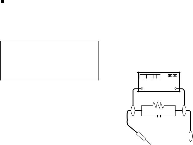
5.To be sure that no shock hazard exists, check for leakage current in the following manner.
•Use an AC voltmeter having with 5000 ohm per volt, or higher, sensitivity or measure the AC voltage drop across the resistor.
•Connect the resistor connection to all exposed metal parts having a return to the chassis (antenna, metal cabinet, screw heads, knobs and control shafts, escutcheon, etc.) and measure the AC voltage drop across the resistor.
All checks must be repeated with the AC cord plug connection reversed. (If necessary, a nonpolarized adaptor plug must be used only for the purpose of completing these checks.)
Any reading of 1.05 V peak (this corresponds to 0.7 mA peak AC.) or more is excessive and indicates a potential shock hazard which must be corrected before returning the monitor to the owner.
DVM
AC SCALE
1.5k ohm
10W
0.15 µF
TEST PROBE
•Plug the AC cord directly into a 220~240 volt AC outlet.
•Using two clip leads, connect a 1.5k ohm, 10 watt resistor paralleled by a 0.15µF capacitor in series with all exposed metal cabinet parts and a known earth ground, such as electrical conduit or electrical ground connected to an earth ground.
TO EXPOSED |
CONNECT TO |
METAL PARTS |
KNOWN EARTH |
|
GROUND |
///////////////////////////////////////////////////////////////////////////////////////////////////////////////////////////////////////////////////////////////////////////////////////////////////////////////////////////////////////////
SAFETY NOTICE
Many electrical and mechanical parts in LCD color television have special safety-related characteristics.
These characteristics are often not evident from visual inspection, nor can protection afforded by them be necessarily increased by using replacement components rated for higher voltage, wattage, etc.
Replacement parts which have these special safety characteristics are identified in this manual; electrical components having such features
are identified by “ ” and shaded areas in the Replacement Parts List and Schematic Diagrams.
For continued protection, replacement parts must be identical to those used in the original circuit.
The use of a substitute replacement parts which do not have the same safety characteristics as the factory recommended replacement parts shown in this service manual, may create shock, fire or other hazards.
///////////////////////////////////////////////////////////////////////////////////////////////////////////////////////////////////////////////////////////////////////////////////////////////////////////////////////////////////////////
i
LC-40/46LE810E, LC-40/46LX810E
Precautions for using lead-free solder
Employing lead-free solder
•“PWBs” of this model employs lead-free solder. The LF symbol indicates lead-free solder, and is attached on the PWBs and service manuals. The alphabetical character following LF shows the type of lead-free solder.
Example:
L |
F |
a |
L |
F |
a/a |
||||
|
|
|
|
|
|
|
|
|
|
Indicates lead-free solder of tin, silver and copper.
Indicates lead-free solder of tin, silver and copper.
Using lead-free wire solder
•When fixing the PWB soldered with the lead-free solder, apply lead-free wire solder. Repairing with conventional lead wire solder may cause damage or accident due to cracks.
As the melting point of lead-free solder (Sn-Ag-Cu) is higher than the lead wire solder by 40 °C, we recommend you to use a dedicated soldering bit, if you are not familiar with how to obtain lead-free wire solder or soldering bit, contact our service station or service branch in your area.
Soldering
•As the melting point of lead-free solder (Sn-Ag-Cu) is about 220 °C which is higher than the conventional lead solder by 40 °C, and as it has poor solder wettability, you may be apt to keep the soldering bit in contact with the PWB for extended period of time. However, Since the land may be peeled off or the maximum heat-resistance temperature of parts may be exceeded, remove the bit from the PWB as soon as you confirm the steady soldering condition.
Lead-free solder contains more tin, and the end of the soldering bit may be easily corroded. Make sure to turn on and off the power of the bit as required.
If a different type of solder stays on the tip of the soldering bit, it is alloyed with lead-free solder. Clean the bit after every use of it. When the tip of the soldering bit is blackened during use, file it with steel wool or fine sandpaper.
•Be careful when replacing parts with polarity indication on the PWB silk.
Lead-free wire solder for servicing
Part No. |
|
|
Description |
Code |
|
ZHNDAi123250E |
J |
φ0.3mm 250g |
(1roll) |
BL |
|
ZHNDAi126500E |
J |
φ0.6mm |
500g |
(1roll) |
BK |
ZHNDAi12801KE |
J |
φ1.0mm |
1kg (1roll) |
BM |
|
ii

LC-40/46LE810E, LC-40/46LX810E
End of life disposal
End of life disposal
iii
LC-40/46LE810E, LC-40/46LX810E
OUTLINE
MAJOR SERVICE PARTS
PWB UNIT
Ref No. |
Parts Code |
Description |
N |
DKEYDF455FM03 |
MAIN Unit (*1) |
N |
DUNTKF494FM02 |
R/C, LED Unit |
N |
DUNTKF493FM03 |
ICON Unit |
N |
RUNTKA692WJQZ |
TOUCH SENSOR Unit (*2) |
N |
RUNTKA685WJQZ |
POWER Unit (LC-40LE810E/LX810E) |
N |
RUNTKA686WJQZ |
POWER Unit (LC-46LE810E/LX810E) |
N |
RUNTK4512TPZC |
LCD CONTROL Unit (LC-40LE810E/LX810E) |
N |
RUNTK4437TPZE |
LCD CONTROL Unit (LC-46LE810E/LX810E) |
N |
RUNTK4462TPZZ |
LED PWB Unit, x4 (LC-40LE810E/LX810E) |
N |
RUNTK4461TPZZ |
LED PWB Unit, x4 (LC-46LE810E/LX810E) |
NOTE: (*1) Replace MAIN Unit (DKEYDF455FM03) in case of IC8401 or IC3302 failure.
(*2) TOUCH SENSOR Unit (RUNTKA692WJQZ) reuse will be impossible, once it is stuck on front cabinet and exfoliates. Therefore, please exchange of a TOUCH SENSOR Unit in the case of front cabinet exchange.
OTHER UNIT
Ref No. |
Parts Code |
Description |
|
N |
R1LK400D3LWF2Y |
40” LCD Panel Module Unit (LC-40LE810E/LX810E) |
|
N |
R1LK460D3LWA2Y |
46” LCD Panel Module Unit (LC-46LE810E/LX810E) |
|
IC FOR EXCLUSIVE USE OF THE SERVICE |
|
||
|
|
|
|
Ref No. |
Parts Code |
Description |
Q’ty |
IC501 |
RH-iXD108WJQZS |
IC 24LC21AT-I/SN |
1 |
IC2002 |
RH-iXC786WJNJQ |
IC R5F364A6NFB |
1 |
SERVICE JIGS |
|
|
|
|
|
|
|
Ref No. |
Parts Code |
Description |
Q’ty |
N |
QCNW-G616WJQZ |
Main Unit to LCD Control Unit (LW) |
1 |
N |
QCNW-G625WJQZ |
Main Unit to Power Unit (PL) |
1 |
N |
QCNW-H184WJQZ |
Main Unit to Power Unit (PD) |
1 |
N |
QCNW-H185WJQZ |
Main Unit to Power (LED Drive) Unit (LB) |
1 |
N |
QCNW-K594WJQZ |
Main Unit to R/C, LED Unit (RA) |
1 |
N |
QCNW-K595WJQZ |
Main Unit to Speaker (SP) |
1 |
N |
QCNW-K597WJQZ |
Main Unit to Woofer (SB) |
1 |
iv

LC-40/46LE810E, LC-40/46LX810E
CHAPTER 1. SPECIFICATIONS
[1] SPECIFICATIONS
Item |
|
|
LCD COLOUR TV (40"/81.28 cm), |
LCD COLOUR TV (46"/116.84 cm), |
|
|
|
LC-40LE810E/LC-40LX810E |
LC-46LE810E/LC-46LX810E |
|
|
|
|
|
LCD panel |
|
|
Advanced Super View & BLACK TFT |
Advanced Super View & BLACK TFT |
|
|
|
LCD (40"/81.28 cm) |
LCD (46"/116.84 cm) |
|
|
|
|
|
Resolution |
|
|
1,920 x 1,080 x 4 pixels |
|
|
|
|
|
|
Video colour system |
|
PAL/SECAM/NTSC 3.58/NTSC 4.43/PAL 60 |
||
|
|
|
|
|
TV function |
TV-standard |
Analogue |
CCIR (B/G, I, D/K, L/L’) |
|
|
|
|
|
|
|
|
Digital |
DVB-T (2K/8K OFDM), DVB-C |
|
|
|
|
|
|
|
Receiving |
VHF/UHF |
IR A ch-E69 ch (Digital), E2-E69 ch, F2-F10 ch, I21-I69 ch, IR A-IR J ch |
|
|
channel |
|
|
|
|
CATV |
Hyper-band, S1-S41 ch |
|
|
|
|
|
||
|
|
|
|
|
|
TV-tuning system |
|
Auto Preset 999 ch (non-Nordic [DTV]), Auto Preset 9999 ch (Nordic [DTV]), |
|
|
|
|
Auto Preset 99 ch (ATV), Auto Label, Auto Sort |
|
|
|
|
|
|
|
STEREO/BILINGUAL |
NICAM/A2 |
|
|
|
|
|
|
|
Audio amplifier |
|
|
10 W x 2/15 W x 1 |
|
|
|
|
|
|
Speaker |
|
|
(234 mm x 22 mm) x 2/Ø 110 mm |
|
|
|
|
|
|
Terminals |
Antenna |
|
UHF/VHF 75 Din type (analogue & digital) |
|
|
|
|
|
|
|
RS-232C |
|
D-Sub 9 pin male connector |
|
|
|
|
|
|
|
EXT 1 |
|
SCART (AV input, Y/C input, RGB input, TV output) |
|
|
|
|
|
|
|
EXT 2 |
|
RCA pin (AV input/AUDIO L/R) |
|
|
|
|
|
|
|
EXT 3 |
|
15 pin mini D-sub |
|
|
|
|
|
|
|
HDMI 1 (EXT 4) |
|
HDMI (ARC) |
|
|
|
|
|
|
|
HDMI 2 (EXT 5) |
|
HDMI |
|
|
|
|
|
|
|
HDMI 3 (EXT 6) |
|
HDMI |
|
|
|
|
|
|
|
HDMI 4 (EXT 7) |
|
HDMI |
|
|
|
|
|
|
|
USB |
|
USB |
|
|
|
|
|
|
|
ETHERNET (10/100) |
Home network connector (only the 820 model series) |
||
|
|
|
|
|
|
HDMI 2/EXT 3 AUDIO (L/R) |
Ø 3.5 mm jack*1 |
|
|
|
DIGITAL AUDIO OUTPUT |
Optical S/PDIF digital audio output |
|
|
|
|
|
|
|
|
C. I. (Common Interface) |
EN50221, R206001, CI Plus specification |
||
|
|
|
|
|
|
OUTPUT/Headphones |
RCA pin (AUDIO R/L)/Ø 3.5 mm jack (audio output) |
||
|
|
|
|
|
OSD language |
|
|
Czech, Danish, Dutch, English, Estonian, Finnish, French, German, Greek, |
|
|
|
|
Hungarian, Italian, Latvian, Lithuanian, Norwegian, Polish, Portuguese, Russian, |
|
|
|
|
Slovak, Slovene, Spanish, Swedish, Turkish, Ukrainian |
|
|
|
|
|
|
Power requirement |
|
AC 220 - 240 V, 50 Hz |
|
|
|
|
|
||
Power consumption (method IEC62087) |
127 W (0.2 W standby*2) |
147 W (0.2 W standby*2) |
||
Weight |
|
|
16.0 kg (without stand), |
20.5 kg (without stand), |
|
|
|
19.5 kg (with stand) |
26.0 kg (with stand) |
|
|
|
|
|
Operating temperature |
|
0 °C to + 40 °C |
|
|
|
|
|
|
|
*1 The HDMI 2 and EXT 3 terminals can both use the same audio input terminal.
*2 Standby power consumption applies when the TV is set to not receive EPG data.
•As a part of our policy of continuous improvement, SHARP reserves the right to make design and specification changes for product improvement without prior notice. The performance specification figures indicated are nominal values of production units. There may be some deviations from these values in individual units.
1 – 1
LC-40/46LE810E, LC-40/46LX810E
CHAPTER 2. OPERATION MANUAL
[1] OPERATION MANUAL
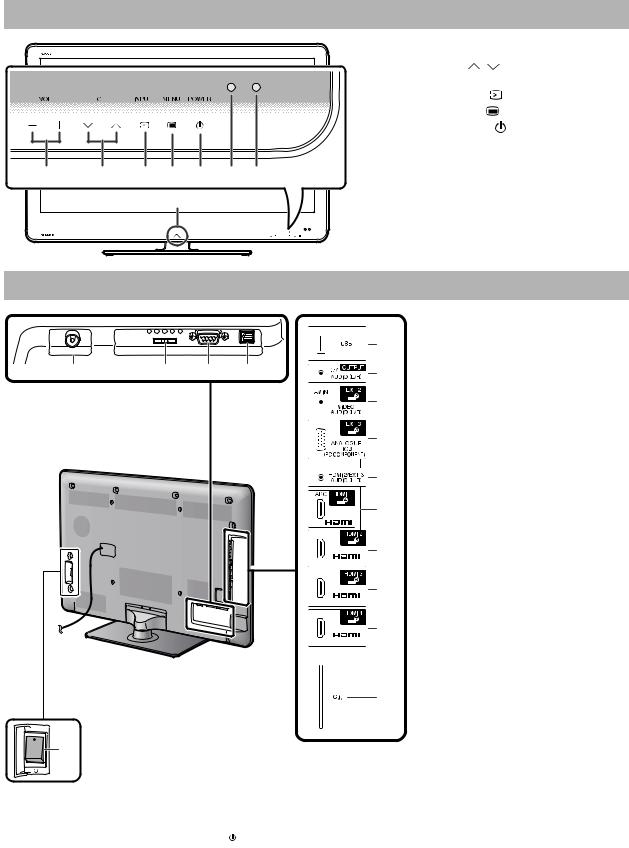
TV (front view)
|
|
|
1 |
VOL -/+ |
(Volume buttons) |
|
|
|
2 |
CH / |
(Programme [channel] |
|
|
|
|
buttons) |
|
|
|
|
3 |
INPUT |
(Input source button) |
|
|
|
4 |
MANU |
(Menu button) |
|
|
|
5 |
POWER |
(Power button) |
|
|
|
6 |
OPC sensor |
|
|
|
|
7 |
Remote control sensor |
|
1 |
2 |
3 4 5 6 7 |
8 |
Illumination LED |
|
|
|
8 |
|
|
|
TV (rear view)
|
|
|
|
|
1 |
Antenna terminal |
|
|
|
|
5 |
2 |
EXT 1 (RGB) terminal |
|
|
|
|
3 |
RS-232C terminal |
|
|
|
|
|
|
||
1 |
2 |
3 |
4 |
6 |
4 |
DIGITAL AUDIO OUTPUT |
|
terminal |
|||||
|
|
|
|
|
|
|
|
|
|
|
7 |
5 |
USB terminal |
|
|
|
|
|
|
|
|
|
|
|
|
6 |
OUTPUT (Headphones/AUDIO |
|
|
|
|
8 |
|
(L/R)) terminal |
|
|
|
|
7 |
EXT 2 (AV IN/VIDEO/AUDIO (L/R)) |
|
|
|
|
|
|
||
|
|
|
|
*1 |
|
terminal |
|
|
|
|
|
|
|
|
|
|
|
9 |
8 |
EXT 3 (ANALOGUE RGB (PC/ |
|
|
|
|
|
|
COMPONENT)) terminal |
|
|
|
|
10 |
9 |
HDMI 2/EXT 3 AUDIO (L/R) jack |
|
|
|
|
|
10 |
HDMI 1 (HDMI/ARC) terminal |
|
|
|
|
11 |
11 |
HDMI 2 (HDMI) terminal |
|
|
|
|
12 |
HDMI 3 (HDMI) terminal |
|
|
|
|
|
|
||
|
|
|
|
|
13 |
HDMI 4 (HDMI) terminal |
|
|
|
|
12 |
14 |
C.I. (COMMON INTERFACE) slot |
|
|
|
|
|
15 |
MAIN POWER switch |
13 |
WARNING |
|
• Excessive sound pressure from earphones |
||
|
||
|
and headphones can cause hearing loss. |
|
|
• Do not set the volume at a high level. |
|
|
Hearing experts advise against extended |
|
|
listening at high volume levels. |
|
14 |
|
|
*2 |
|
|
15 |
|
*1 The HDMI 2 and EXT 3 terminals can both use the same audio input terminal (HDMI 2/EXT 3 AUDIO (L/R)). However, the proper item must be selected in the “Audio select” menu.
*2 When the MAIN POWER switch is turned off ( ), the amount of electric power consumed will be reduced to 0.01 W or less. However, unlike when unplugging the AC cord, the power is not completely disconnected.
2 – 1
LC-40/46LE810E, LC-40/46LX810E
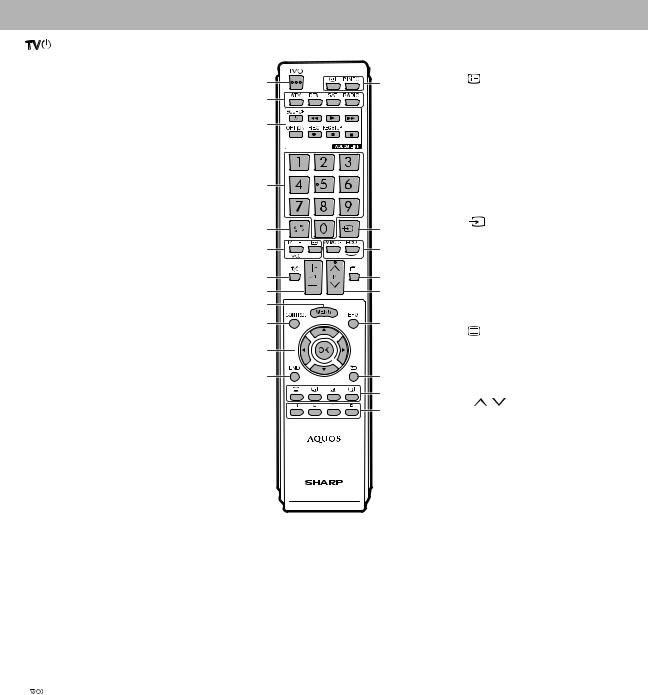
Remote control unit
1 |
(Standby/On) |
|
|
12 |
END |
|
|
|
|
|
Exit the “Menu” screen. |
2 |
ATV |
1 |
13 |
13 |
(Display information) |
|
Press to access conventional |
|
Press to display the station |
||
|
2 |
|
|
||
|
analogue TV mode. |
|
|
information (channel number, signal, |
|
|
|
|
|
||
|
DTV |
3 |
|
|
etc.) in the upper right corner of the |
|
|
|
screen. |
||
|
Press to access digital TV mode. |
|
|
|
|
|
|
|
|
|
|
SAT |
|
|
|
P. INFO |
|
|
|
|
|
Press to display programme |
||
|
This function is not available. |
|
|
|
||
|
|
|
|
information transmitted through |
||
|
|
4 |
|
|
||
|
|
|
|
digital video broadcasting (DTV |
||
|
RADIO |
|
|
|
||
|
|
|
|
only). |
||
|
DTV: Switch between radio and |
|
|
|
||
|
|
|
14 |
|
(INPUT) |
|
|
data mode. |
5 |
14 |
|
||
|
|
Select an input source. |
||||
|
• When only data broadcasting |
|
||||
|
|
|
|
|||
|
6 |
15 |
|
|
|
|
|
(no radio broadcasting) is |
15 |
AV MODE |
|||
|
|
|
||||
|
transmitted by DVB, the radio |
7 |
16 |
|
Select a video setting. |
|
|
broadcasting will be skipped. |
|
ECO (Standard/Advanced/Off) |
|||
|
|
8 |
17 |
|
||
3 |
AQUOS LINK buttons |
|
Select “Energy save” setting. |
|||
9 |
|
|
||||
|
If external equipment such as a |
|
|
|
|
|
|
|
|
|
|
|
|
|
AQUOS BD player is connected via |
10 |
18 |
16 |
|
(Teletext) |
|
HDMI cables and is AQUOS LINK |
|
|
|
||
|
|
|
|
ATV: Display analogue teletext. |
||
|
compatible, you can use these |
11 |
|
|
||
|
|
|
DTV: Select MHEG-5 and teletext |
|||
|
AQUOS LINK buttons. |
|
|
|
||
|
|
|
|
for DTV. |
||
|
|
12 |
19 |
|
||
|
|
|
|
|
||
|
|
|
20 |
17 |
P |
/ |
|
|
|
21 |
|||
|
|
|
|
Select the TV channel. |
||
|
|
|
|
|
||
4Numeric buttons 0_9
Set the channel.
Enter desired numbers.
Set the page in teletext mode.
•When the five Nordic countries (Sweden, Norway, Finland, Denmark or Iceland) are selected in the country setting from “Auto installation”, DTV services are four digits. When another country is selected, DTV services are three digits.
5 (Flashback)
Press to return to the previously selected channel or external input.
6 (Sound mode)
Select a sound multiplex mode.
 (Wide mode)
Select a wide mode.
7 (Mute)
TV sound on/off.
8 +/- (Volume)
Increase/decrease TV volume.
9MENU
“Menu” screen on/off.
10CONTROL
Press to display the panel to operate some functions on the screen.
11 /
/ /
/ /
/ (Cursor)
Select a desired item on the setting screen.
OK
Execute a command within the “Menu” screen.
ATV/DTV: Display “CH list” when no other “Menu” screen is running.
18EPG
DTV: Display the EPG screen.
19 (Return)
Return to the previous “Menu” screen.
20Buttons for useful operations
 (Subtitle)
Switch subtitle languages on/off .
 (Reveal hidden teletext)
 (Subpage)
 (Freeze/Hold)
Press to freeze a moving image on the screen.
Teletext: Stop updating teletext pages automatically or release the hold mode.
21R/G/Y/B (Colour) buttons
The coloured buttons are correspondingly used to select the coloured items on the screen (e.g., EPG, MHEG-5, teletext).
2 – 2
LC-40/46LE810E, LC-40/46LX810E
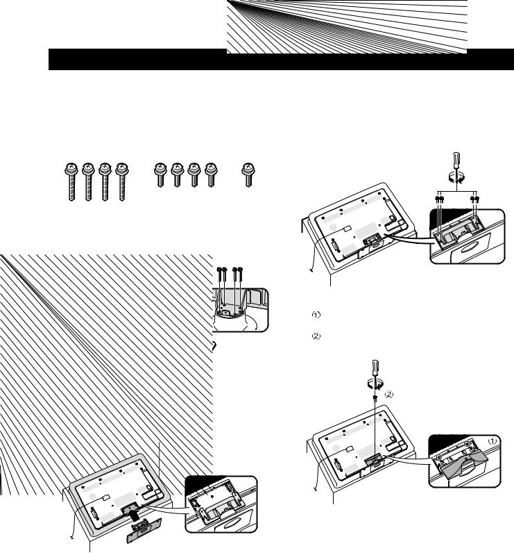
Attaching the stand unit
•Before performing work, spread cushioning over the surface on which you will be laying the TV. This will prevent it from being damaged.
CAUTION
•Attach the stand in the correct direction.
•Be sure to follow the instructions. Incorrect installation of the stand may result in the TV falling over.
1Confirm that there are nine screws (four long screws and five short screws) with the stand unit.
2Attach the supporting post for the stand unit onto the base using the four long screws with a screwdriver as shown.
Supporting
post
3Insert the stand into the openings on the bottom of the TV (hold the stand so it will not drop from the edge of the base area).
Soft cushion
4Insert and tighten four short screws into the four holes on the rear of the TV.
5Attaching the stand cover.
Slide the stand cover into the two catches on the stand base.
Insert and tighten a short screw into the hole on the centre of the stand cover.
NOTE
•To detach the stand unit, perform the steps in reverse order.
•A screwdriver is not supplied with this product.
•The stand base is made of glass. Therefore, be careful not to drop the stand base or apply pressure to it.
•Do not place heavy objects on the stand base.
2 – 3
LC-40/46LE810E, LC-40/46LX810E
CHAPTER 3. DIMENSIONS
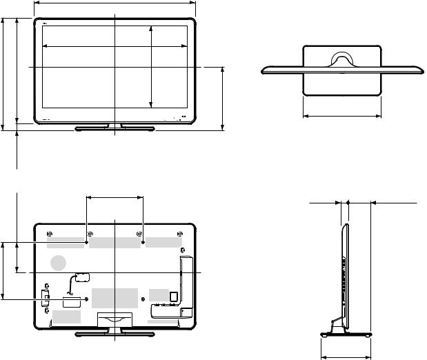
[1] DIMENSIONS (LC-40LE810E/LX810E)
|
|
|
|
992.0 |
|
|
|
|
|
992,0 |
|
|
|
|
|
887.8 |
|
706.0 |
706,0 |
658.0 |
658,0 |
887,8 |
|
500.4 |
500,4 |
|
48.0 |
48,0 |
|
|
132.0 |
132,0 |
300.0 |
|
300,0 |
||
|
|
|
|
300.0 |
300,0 |
|
|
404.0 |
404,0 |
Unit: mm
450.0
450,0
39.5124.0
39,5 124,0
275.0
275,0
3 – 1
[2] DIMENSIONS (LC-46LE810E/LX810E)
1125.0
1125,0
|
|
|
|
1020.8 |
|
|
|
784.0 |
784,0 |
733.0 |
733,0 |
1020,8 |
|
|
|
575.4 |
575,4 |
444.0 |
444,0 |
||||
|
|
51.0 |
51,0 |
|
|
|
|
|
|
211.0 |
211,0 |
400.0 |
|
|
|
|
|
400,0 |
|
|
|
||
|
|
|
|
|
|
|
|
|
400.0 |
400,0 |
|
|
|
|
|
LC-40/46LE810E, LC-40/46LX810E
Unit: mm
540.0
540,0
39.5157.1
39,5 157,1
340.0
340,0
3 – 2
LC-40/46LE810E, LC-40/46LX810E
CHAPTER 4. REMOVING OF MAJOR PARTS
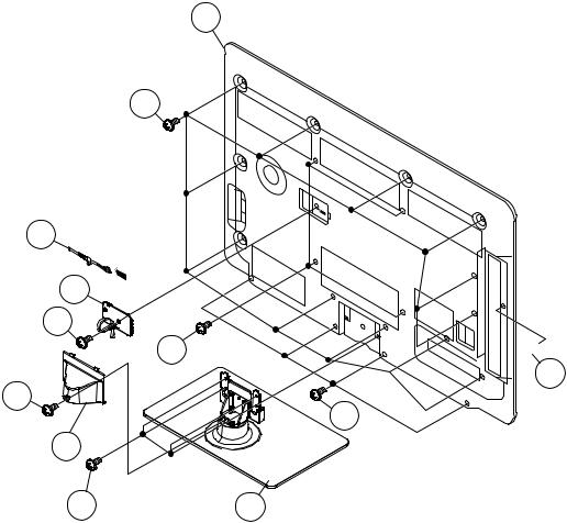
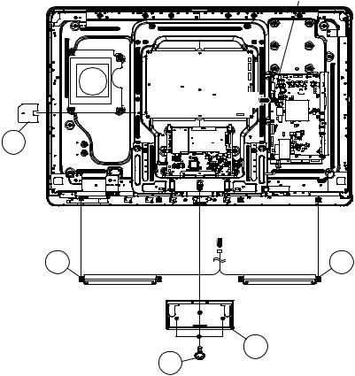
[1] REMOVING OF MAJOR PARTS (LC-40LE810E/LX810E)
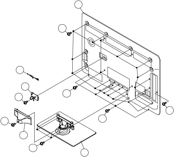
1. Removing of Stand Unit and Rear Cabinet Ass’y.
1.Remove the 1 lock screw  and detach the Support Cover
  .
.
2.Remove the 4 lock screw  and detach the Stand Unit
  .
.
3.Remove the 1 lock screw  and detach the AC Cord Cover
  .
.
4.Disconnect AC wire and detach the AC Cord  .
.
5.Remove the 4 lock screw  , 1 lock screw
  , 4 lock screws
  and 12 lock screws
  and detach the Rear Cabinet Ass’y
  .
.
12 Rear Cabinet Ass'y
11
AC Cord 7 |
[AC] |
[AC]
AC Cord Cover 6
5
8 
 9
9
1
10
Support Cover 2
3 |
Stand Unit 4 |
4 – 1
LC-40/46LE810E, LC-40/46LX810E
2. Removing of Speaker-L/R.
1.Remove the 1 lock screw  and detach the Stand Cover
  .
.
2.Disconnect SP wire.
3.Detach the Speaker-L  , Speaker-R
  .
.
4.Detach the Insulation Sheet (AC)  .
.
MAIN Unit
[SP]


5
Insulation
Sheet (AC)
[SP]
Speaker-R 4 |
3 Speaker-L |
2 Stand Cover
1
4 – 2
LC-40/46LE810E, LC-40/46LX810E
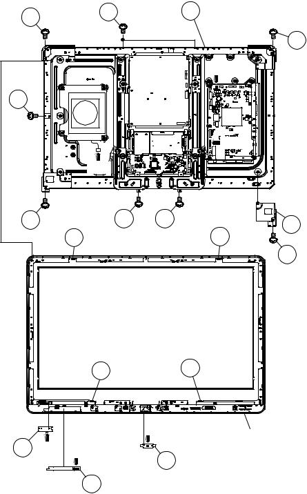
3. Removing of 40” LCD Panel Module Unit, TOUCH SENSOR Unit, ICON Unit, R/C, LED Unit, Front Cabinet Ass’y.
1.Disconnect RA, SB wire.
2.Detach the TOUCH SENSOR Unit  . (RK)
3.Detach the ICON Unit  . (RI)
4.Detach the R/C, LED Unit  . (RA)
5.Remove the 1 lock screw  and detach the LCD Angle (Bottom-R)
  .
.
6.Remove the 5 lock screws  , 3 lock screws
  , 4 Hooks
  and detach the 40” LCD Panel Module Unit
  . NOTE: The TOUCH SENSOR Unit removed once is not reusable.
6 |
7 |
|
9 40" LCD Panel Module Unit |
|
|
|
|
|
|
|
|
|
6 |
|
|
|
|
[SB] |
|
7 |
|
|
|
|
|
|
|
[RA] |
|
|
[SB] |
|
|
|
6 |
6 |
6 |
5 |
LCD Angle |
|
|
|
||
|
8 |
|
8 |
(Bottom-R) |
|
|
|
4 |
|
8 8
[RI] |
Front Cabinet Ass'y |
|
3 [RA] [RK] |
2 ICON Unit |
|
R/C, LED Unit |
||
|
||
|
1 TOUCH SENSOR Unit |
4 – 3
LC-40/46LE810E, LC-40/46LX810E
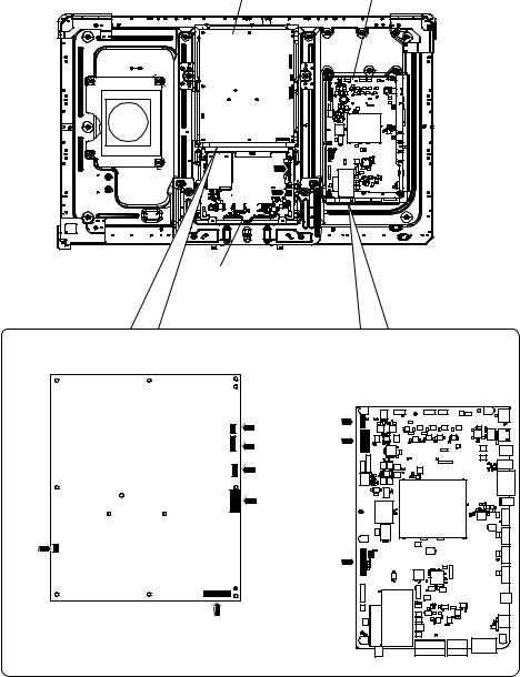
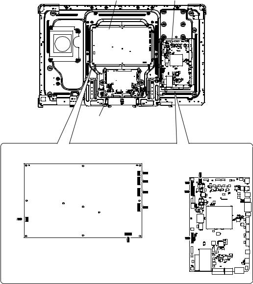
4. Removing of Connectors
1.Disconnect the following connectors from the MAIN Unit. (LB, PD, LW)
2.Disconnect the following connectors from the POWER Unit. (L1, L2, LB, PD, PL, AS)
3.Disconnect the following connectors from the LCD CONTROL Unit. (LW, PL)
POWER Unit |
MAIN Unit |
[LW] |
[PL] |
LCD CONTROL Unit
POWER Unit |
MAIN Unit |
[L1] |
[LB] |
[L2] |
[PD] |
[LB] |
|
[PD] |
|
[AS] |
[LW] |
|
|
[PL] |
|
4 – 4
LC-40/46LE810E, LC-40/46LX810E
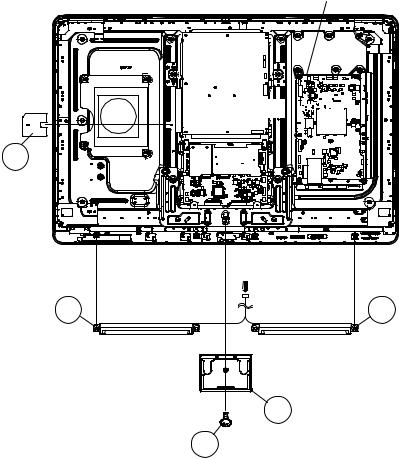
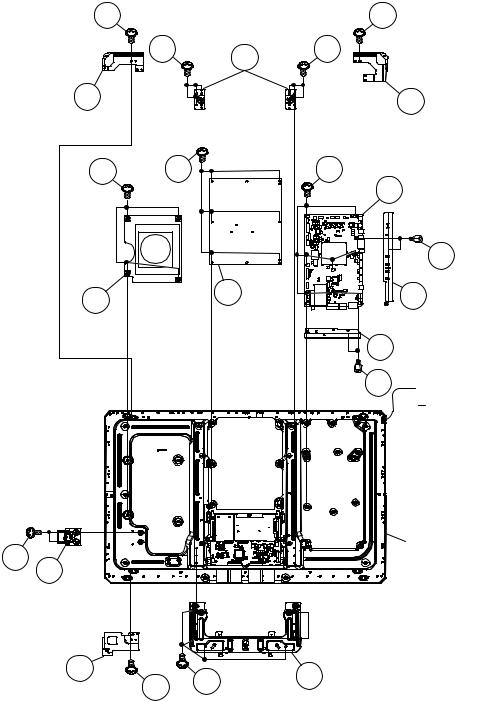
5. Removing of MAIN Unit, POWER Unit, Woofer, Stand Angle.
1.Remove the 7 lock screws  and detach the MAIN Unit
2.Remove the 2 lock screws  and detach the Terminal Angle (Bottom)
  .
.
3.Remove the 2 lock screws  and detach the Terminal Angle (Side)
  .
.
4.Remove the 6 lock screws  and detach the POWER Unit
  .
.
5.Remove the 4 lock screws  and detach the Woofer
  .
.
6.Remove the 8 lock screws  and detach the 2 VESA Angle
  .
.
7.Remove the 1 lock screw  and detach the LCD Angle (Bottom-L)
  .
.
8.Remove the 1 lock screw  and detach the LCD Angle (Top-R)
  .
.
9.Remove the 1 lock screw  and detach the LCD Angle (Top-L)
  . 10.Remove the 6 lock screws
  and detach the Stand Angle
  .
.
11.Remove the 2 lock screws  and detach the ECO Switch with Holder
  .
.
17
LCD Angle 18
(Top-L)
9
10 Woofer
21
22
ECO Switch
with Holder
LCD Angle 14 (Bottom-L)
|
VESA |
15 |
|
Angle |
|
11 |
12 |
11 |
|
|
16 LCD Angle
(Top-R)
7
8
POWER
Unit
13 19
1
2 MAIN Unit
5
6 Terminal Angle
(Side)
4 Terminal Angle
(Bottom)
3 [L1]
[L1]

 [L2]
[L2]
40" LCD Panel
Module Unit
20 Stand Angle
4 – 5
LC-40/46LE810E, LC-40/46LX810E
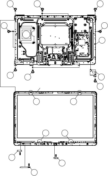
[2] REMOVING OF MAJOR PARTS (LC-46LE810E/LX810E)
1. Removing of Stand Unit and Rear Cabinet Ass’y.
1.Remove the 1 lock screw  and detach the Support Cover
  .
.
2.Remove the 4 lock screws  and detach the Stand Unit
  .
.
3.Remove the 1 lock screw  and detach the AC Cord Cover
  .
.
4.Disconnect AC wire and detach the AC Cord  .
.
5.Remove the 4 lock screws  , 1 lock screw
  , 4 lock screws
  and 16 lock screws
  and detach the Rear Cabinet Ass’y
  .
.
12 Rear Cabinet Ass'y
11
[AC]
AC Cord 7
 [AC]
[AC]
AC Cord Cover 6
8
5
9
1 |
10 |
|
Support Cover 2
3
4 Stand Unit
4 – 6
LC-40/46LE810E, LC-40/46LX810E
2. Removing of Speaker-L/R.
1.Remove the 3 lock screws  and detach the Stand Cover
  .
.
2.Disconnect SP wire.
3.Detach the Speaker-L  , Speaker-R
  .
.
4.Detach the Insulation Sheet (AC)  .
.
MAIN Unit
[SP] |
|
5 |
|
Insulation |
|
Sheet (AC) |
|
[SP] |
|
Speaker-R 4 |
3 Speaker-L |
2 |
Stand Cover |
1 |
|
4 – 7
LC-40/46LE810E, LC-40/46LX810E
3. Removing of 46” LCD Panel Module Unit, TOUCH SENSOR Unit, ICON Unit, R/C, LED Unit, Front Cabinet Ass’y.
1.Remove the 1 lock screw  and detach the LCD Angle (Bottom-R)
  .
.
2.Remove the 5 lock screws  , 5 lock screws
  , 4 Hooks
  and detach the 46” LCD Panel Module Unit
  .
.
3.Disconnect RA wire.
4.Detach the TOUCH SENSOR Unit  . (RK)
5.Detach the ICON Unit  . (RI)
6.Detach the R/C, LED Unit  . (RA)
NOTE: The TOUCH SENSOR Unit removed once is not reusable.
3 |
4 |
3 |
4 |
|
4 |
|
|
6 |
|
|
46" LCD Panel |
|
[RA] |
Module Unit |
|
|
3 |
3 |
2 LCD Angle |
|
||
|
|
(Bottom-R) |
|
Front Cabinet Ass'y |
1 |
|
5 |
5 |
55
|
|
[RI] |
9 [RA] |
|
|
R/C, LED Unit |
[RK] |
8 ICON Unit |
|
||
|
7 |
TOUCH SENSOR Unit |
4 – 8
LC-40/46LE810E, LC-40/46LX810E
4. Removing of Connectors
1.Disconnect the following connectors from the MAIN Unit. (SB, LB, PD, LW)
2.Disconnect the following connectors from the POWER Unit. (L1, L2, LB, PD, PL, AS)
3.Disconnect the following connectors from the LCD CONTROL Unit. (LW, PL)
POWER Unit |
MAIN Unit |
|
|
|
|
|
|
|
|
|
|
|
|
|
|
|
|
[LW]

[PL] 

LCD CONTROL Unit
POWER Unit |
MAIN Unit |
[L1] |
[SB] |
|
|
[L2] |
[LB] |
[LB] |
[PD] |
[PD] |
|
[AS] |
|
|
[LW] |
[PL] |
|
4 – 9
LC-40/46LE810E, LC-40/46LX810E
5. Removing of MAIN Unit, POWER Unit, Sub Woofer, Stand Angle.
1.Remove the 7 lock screws  and detach the MAIN Unit
2.Remove the 2 lock screws  and detach the Terminal Angle (Bottom)
  .
.
3.Remove the 2 lock screws  and detach the Terminal Angle (Side)
  .
.
4.Remove the 6 lock screws  and detach the POWER Unit
  .
.
5.Remove the 4 lock screws  and detach the Woofer
  .
.
6.Remove the 1 lock screw  and detach the LCD Angle (Top-R)
  .
.
7.Remove the 1 lock screw  and detach the LCD Angle (Top-L)
  .
.
8.Remove the 1 lock screw  and detach the LCD Angle (B-C-A)
  .
.
9.Remove the 1 lock screw  and detach the LCD Angle (Bottom-L)
  . 10.Remove the 1 lock screw
  and detach the LCD Angle (B-C-B)
  .
.
11.Remove the 8 lock screws  and detach the Stand Angle
  . 12.Remove the 2 lock screws
  and detach the ECO Switch with Holder
  .
.
13 |
11 |
LCD Angle 14
(Top-L)
|
|
|
1 |
12 LCD Angle (Top-R) |
|
|
7 |
|
|
|
|
|
|
|
2 |
MAIN Unit |
|
|
|
|
|
||
9 |
|
|
|
|
5 |
|
|
|
|
|
|
|
|
8 POWER |
|
|
6 Terminal Angle |
|
|
Unit |
|
|
|
|
|
|
|
(Side) |
|
10 |
|
|
|
|
|
|
|
|
4 |
Terminal Angle |
|
Woofer |
|
[SB] |
|
||
|
|
|
(Bottom) |
||
|
|
|
|
||
|
|
|
|
3 |
|
|
|
|
|
[L1] |
|
|
|
|
|
|
|
|
|
|
|
|
[L2] |
23 |
|
|
46" LCD Panel |
|
|
|
|
||
24 |
|
|
Module Unit |
|
ECO Switch |
|
|
|
|
with Holder |
|
|
|
|
|
|
|
22 Stand Angle |
|
|
|
21 |
20 LCD Angle (B-C-B) |
|
|
|
|
||
LCD Angle 18 |
|
|
19 |
|
(Bottom-L) |
17 |
15 |
||
|
||||
|
|
16 LCD Angle (B-C-A)
4 – 10
LC-40/46LE810E, LC-40/46LX810E
CHAPTER 5. ADJUSTMENT
[1] ADJUSTMENT PROCEDURE
1. Adjustment method after PWB and/or IC replacement due to repair
The unit is set to the optimum at the time of shipment from the factory.
If any value should become improper or any adjustment is necessary due to the part replacement, make an adjustment according to the following procedure.
1.Procure the following units in order to replace the main unit MAIN UNIT: DKEYDF455FM03
NOTE: [Caution when replacing ICs in the main unit (IC501, IC2002)]
The above ICs are EEPROMs storing the EDID data of PC, and Monitor microcomputer.
Before replacing the relevant part, procure the following parts in which the data have been rewritten.
IC501 |
RH-iXD108WJQZS |
PC EDID |
IC2002 |
RH-iXC786WJNJQ |
Monitor microcomputer |
NOTE: [Caution when replacing ICs in the main unit (IC8401, IC3302)]
When replacing either IC8401 or IC3302, exchange MAIN units for DKEYDF455FM01
Each part should not be individually exchanged.
IC8401 |
RH-iXC147WJQZQ |
Flash |
IC3302 |
RH-iXC951WJN1Q |
Main CPU |
NOTE: HDMI ROM Writing
After replacing IC1504, execute “HDMI EDID WRITE” on the page 5/21
Please execute it after checking MODEL NAME & INCH SIZE. are correct.
IF MODEL NAME & INCH SIZE. are not correct, set them previously. (Refer to 2)
The ROM data based on information of MODEL NAME & INCH SIZE
1)Enter the process adjustment mode in TV.
2)Use the cursor keys ( /
/ ) and CH keys (
 /
/ ) of R/C to select the item [HDMI EDID WRITE] on the page 5/21.
2.After replacing the LCD panel or LCD control/MAIN UNIT, check MODEL NAME in the following procedure.
1)Enter the process adjustment mode in TV.
2)Use the cursor keys ( /
/ ) and CH keys (
 /
/ ) of R/C to select the item [MODEL NAME] on the page 21/21.
3)Verify that the Model name is displayed.
4)If the Model name doesn't match, select the values of the Model name with the VOL keys (+/-).
5)After selection in Step 4), press the OK key, and it is completed with OK displayed.
6)Use the cursor keys ( /
/ ) and CH keys (
 /
/ ) of R/C to select the item [PANEL_SIZE] on the page 21/21.
7)Verify that the panel size is displayed.
8)If the size doesn't match, select the values of the panel size with the VOL keys (+/-).
9)After selection in Step 8), press the OK key, and it is completed with OK displayed.
3.After replacing the LCD panel or LCD control PWB, adjust the VCOM in the following procedure.
1)Enter the process adjustment mode.
2)Use the cursor keys ( /
/ ) and CH keys (
 /
/ ) of R/C to select the item [VCOM ADJ] on the page 10/21.
3)Press the OK key to verify that the adjustment pattern is displayed.
4)Use VOL keys (+/-) of R/C to adjust the flicker in the center of the screen to minimum.
5)When the optimal state is achieved in Step 4, press the OK key to turn the pattern to OFF.
5 – 1

LC-40/46LE810E, LC-40/46LX810E
2. Method of shuts down for Power supply
Please execute the following procedures to shut down Power supply from the state of normal operation.
1)Keep touching the power supply key on the set for 5 seconds from the state of watching.
*The screen disappears when power supply key is touched, but Keep pushing the power supply key.
2)A central icon lights between 500ms when the power supply shuts down.
Please separate the finger from the power supply key when lighting of a central icon is confirmed
3. Entering and exiting the adjustment process mode
Please execute the following procedures to enter the adjustment process mode when the power supply shuts down.
1)While holding down the “VOL (-)” and “INPUT” keys on the set at once, touch the power supply key on the set. Please separate the fingers from key on the set when boot-up is confirmed with lighting of a central icon etc. After a while, The letter “K” appears on the screen. This state is in Inspection mode.
2)Next, hold down the “VOL (-)” and “CH ( )” keys on the set at once.
Multiple lines of blue characters appearing on the screen indicate that the set is now in the adjustment Process mode. If you fail to enter the adjustment process mode (the display is the same as normal startup), retry the procedure.
3)To exit the adjustment process mode after the adjustment is done, unplug the AC power cord to force off the power.
(When the power is turned off with the remote controler, once unplug the AC power cord and plug it in again. In this case, wait for 10 seconds or so after unplugging.)
CAUTION: Use due care in handling the information described here lest the users should know how to enter the adjustment process mode. If the settings are tampered with in this mode, unrecoverable system damage may result.
4. Remote controler key operation and description of display in adjustment process mode.
1. Key operation
Remote controler key |
Main unit key |
Remote controler key Main unit key Function |
||
CH keys ( |
|
/ ) |
CH ( / ) |
Moving an item (line) by one (UP/DOWN) |
VOL keys (+/-) |
VOL (+/-) |
Changing a selected item setting (+1/-1) |
||
Cursor ( |
/ |
) |
— |
Turning a page (PREVIOUS/NEXT) |
Cursor ( |
/ |
) |
— |
Changing a selected line setting (+10/-10) |
INPUT |
|
|
INPUT |
Input source switching (toggle switching) (TV→EXT1~9, USB) |
OK |
|
|
— |
Executing a function |
RETURN |
|
|
— |
Returning to a present page |
Input mode is switched automatically when relevant adjustment is started so far as the necessary input signal is available.
5 – 2
LC-40/46LE810E, LC-40/46LX810E
5. Description of display
(1) Present page / number of total pages |
(4) Inducing display |
(3) Present colour system |
|
(2) Input that has been selected now |
(5) Inch setting and Model name display |
1/21 INPUT1
MAIN Version
BOOT Version
Monitor Version
T-CON Version/LED CON Version
CPLD Version
CI+INFO/SECURE BOOT
FRC-N Auto Script Version
TCON Master/Slave Serial Version
TOUCH SENSOR UCON VERSION
LAMP ERROR
MONITOR ERR CAUSE
NORMAL STANDBY CAUSE ERROR STANDBY CAUSE
AUTO |
EURO |
xxxxx |
1.00 (E 2009/**/** ) xxxxxxx
xxxxxxx xxxxxxxx/xxxx xxxxxxx xxxxx/YES xxxxxxx xxxxxxx xxxxxxx
0
1)xxxxxx 2)xxxxxx 3)xxxxxx 4)xxxxxx 0 0 0 0 0
|
(6) Item name |
(7) Parameter |
|
|
|
|
|
|
No. |
Description |
Display specification |
(1) |
Present page/number of total pages |
2char/2char Decimal Number mark. |
(2) |
Input that has been selected now |
TUNER/DTV/INPUT1/INPUT2/INPUT3/INPUT5/INPUT6/INPUT7 |
(3) |
Present colour system |
AUTO/N358/N443/PAL/SECAM/480i/580i/1080i/50 etc. |
(4) |
Inducing display |
EUROPE |
(5) |
Inch setting and Model name display |
Inch setting and Model name display |
(6) |
Item name |
Max. 30 char |
(7) |
Parameter |
Max. 60 char |
5 – 3
LC-40/46LE810E, LC-40/46LX810E
6. Adjustment process mode menu
The character string in brackets [ ] will appear as a page title in the adjustment process menu header.
Page |
Line |
Item |
Description |
Remarks (adjustment detail, etc.) |
|
1/21 |
|
|
|
|
|
|
|
1 |
MAIN Version |
1xxx (xxxxx) |
Main software version |
|
|
2 |
BOOT Version |
xxxxxxx |
BOOT Version. |
|
|
3 |
Monitor Version |
xxxxxxx |
Monitor software version |
|
|
4 |
T-CON Version/LED CON Version |
xxxxxxxx/xxxx |
T-CON/H.264 Version |
|
|
5 |
CPLD Version |
xxxxxxx |
CPLD Version. |
|
|
7 |
CI+INFO/SECURE BOOT |
xxxxx/YES |
CI+ Key Information/SECURE BOOT |
|
|
8 |
FRC-N Auto Script Version |
xxxxxxx |
|
|
|
9 |
TCON Master/Slave Serial Version |
xxxxxxx |
|
|
|
10 |
TOUCH SENSOR UCON VERSION |
xxxxxxx |
|
|
|
11 |
LAMP ERROR |
0 |
Number of termination due to lamp error. |
|
|
12 |
MONITOR ERR CAUSE |
1) xxxxxx 2) xxxxxx |
Last error standby cause. |
|
|
|
|
3) xxxxxx 4) xxxxxx |
|
|
|
13 |
NORMAL STANDBY CAUSE |
0 |
Situation that became standby at the end. |
|
|
|
|
|
(Excluding the error) |
|
|
14 |
ERROR STANDBY CAUSE |
0 0 0 0 |
Error standby cause |
2/21 |
|
|
|
|
|
|
|
1 |
INDUSTRY INIT |
Enter |
Initialization to factory settings execution. |
|
|
2 |
INDUSTRY INIT (-Public) |
OFF |
Initialization to factory settings execution. |
|
|
|
|
|
(Public mode is excluded) |
|
|
3 |
PUBLIC MODE |
OFF |
Public mode ON/OFF setting |
|
|
4 |
Center Acutime |
— |
Main operating hours. |
|
|
5 |
RESET |
OFF |
Main operating hours reset. |
|
|
6 |
Backlight Acutime |
— |
Backlight operating hours. |
|
|
7 |
RESET |
OFF |
Backlight operating hours reset. |
|
|
8 |
LAMP ERROR RESET |
OFF |
Lamp error reset. |
|
|
9 |
ADJ PARAM SET |
Enter |
ADJ PARAM SET |
|
|
10 |
VIC XPOS |
0 |
X-coordinate setting for VIC READ |
|
|
11 |
VIC YPOS |
0 |
Y-coordinate setting for VIC READ |
|
|
12 |
VIC SIGNAL TYPE |
MAIN |
Signal type setting for VIC READ |
|
|
13 |
VIC READ |
OFF |
Picture level acquisition function |
|
|
|
|
|
(Level appears in green on the upper right) |
3/21 |
|
|
|
|
|
|
|
1 |
TUNER ADJ |
Enter |
TUNER auto adjustment execution |
|
|
2 |
PAL+TUNER ADJ |
Enter |
PAL TUNER auto adjustment execution |
|
|
3 |
TUNER ADJ (SMPTE) |
Enter |
TUNER auto adjustment execution (SMPTE) |
|
|
4 |
PAL+TUNER ADJ (SMPTE) |
Enter |
PAL TUNER auto adjustment execution (SMPTE) |
|
|
5 |
TUNER ADJ (SMPTE CH57) |
Enter |
TUNER auto adjustment execution (SMPTE CH57) |
|
|
6 |
PAL+TUNER ADJ (SMPTE CH57) |
Enter |
PAL TUNER auto adjustment execution (SMPTE CH57) |
|
|
7 |
TUNER CONTRAST A_GAIN |
16 |
TUNER signal level adjustment |
|
|
8 |
TUNER CONTRAST D_GAIN |
2073 |
TUNER signal level adjustment |
|
|
9 |
TUNER CONTRAST OFFSET |
256 |
TUNER signal level adjustment |
4/21 |
|
|
|
|
|
|
|
1 |
PAL ADJ |
Enter |
PAL adjustment |
|
|
2 |
SECAM ADJ |
Enter |
SECAM adjustment |
|
|
3 |
N358 ADJ |
Enter |
N358 adjustment |
|
|
4 |
PAL CONTRAST A_GAIN |
14 |
PAL contrast adjustment |
|
|
5 |
PAL CONTRAST D_GAIN |
2149 |
PAL contrast adjustment |
|
|
6 |
PAL CONTRAST OFFSET |
255 |
PAL contrast adjustment |
|
|
7 |
SECAM CONTRAST A_GAIN |
14 |
SECAM contrast adjustment |
|
|
8 |
SECAM CONTRAST D_GAIN |
2123 |
SECAM contrast adjustment |
|
|
9 |
SECAM CONTRAST OFFSET |
256 |
SECAM contrast adjustment |
|
|
10 |
N358 CONTRAST A_GAIN |
14 |
N358 contrast adjustment |
|
|
11 |
N358 CONTRAST D_GAIN |
2192 |
N358 contrast adjustment |
|
|
12 |
N358 CONTRAST OFFSET |
255 |
N358 contrast adjustment |
5 – 4
 Loading...