


LC-30HV6U
ENGLISH
LC-30HV6U
LIQUID CRYSTAL TELEVISION
ENGLISH
OPERATION MANUAL
IMPORTANT INFORMATION
WARNING: TO REDUCE THE RISK OF FIRE OR ELECTRIC SHOCK, DO
NOT EXPOSE THIS PRODUCT TO RAIN OR MOISTURE.
CAUTION
RISK OF ELECTRIC SHOCK
DO NOT OPEN
CAUTION: TO REDUCE THE RISK OF ELECTRIC SHOCK,
DO NOT REMOVE COVER (OR BACK).
NO USER-SERVICEABLE PARTS INSIDE.
REFER SERVICING TO QUALIFIED SERVICE
PERSONNEL.
The lightning flash with arrow-head
symbol, within an equilateral
triangle, is intended to alert the user
to the presence of uninsulated
“dangerous voltage” within the
product’s enclosure that may be of
sufficient magnitude to constitute a
risk of electric shock to persons.
The exclamation point within a
triangle is intended to alert the user
to the presence of important
operating and maintenance
(servicing) instructions in the
literature accompanying the product.
IMPORTANT:
To aid reporting in case of loss or theft, please record
the TV’s model and serial numbers in the space
provided. The numbers are located at the rear of the
TV.
Model No.:
Serial No.:
CAUTION:
This product satisfies FCC regulations when shielded cables and connectors are used to connect the unit to other
equipment. To prevent electromagnetic interference with electric appliances such as radios and televisions, use
shielded cables and connectors for connections.
2
IMPORTANT INFORMATION
WARNING: FCC Regulations state that any unauthorized changes or modifications to this equipment not expressly
approved by the manufacturer could void the user’s authority to operate this equipment.
CAUTION: TO PREVENT ELECTRIC SHOCK, MATCH WIDE BLADE OF PLUG TO
WIDE SLOT, FULLY INSERT.
“Note to CATV system installer: This reminder is provided to call the CATV system installer’s attention to Article 820-40 of the
National Electrical Code that provides guidelines for proper grounding and, in particular, specifies that the cable ground shall be
connected to the grounding system of the building, as close to the point of cable entry as practical.”
This product utilizes tin-lead solder, and fluorescent lamp containing a small amount of mercury. Disposal of these
materials may be regulated due to environmental considerations. For disposal or recycling information, please contact
your local authorities or the Electronic Industries Alliance: www.eia.org
CAUTION:
DO NOT PLACE THIS PRODUCT ON AN UNSTABLE CART, STAND, TRIPOD, BRACKET, OR
TABLE. THE PRODUCT MAY FALL CAUSING SERIOUS PERSONAL INJURY AND SERIOUS
DAMAGE TO THE PRODUCT. USE ONLY WITH A CART, STAND, TRIPOD, BRACKET, OR TABLE
RECOMMENDED BY THE MANUFACTURER OR SOLD WITH THE PRODUCT. FOLLOW THE
MANUFACTURER’S INSTRUCTIONS WHEN INSTALLING THE PRODUCT AND USE MOUNTING
ACCESSORIES RECOMMENDED BY THE MANUFACTURER. A PRODUCT AND CART
COMBINATION SHOULD BE MOVED WITH CARE. QUICK STOPS, EXCESSIVE FORCE, AND
UNEVEN SURFACES MAY CAUSE THE PRODUCT AND CART COMBINATION TO OVERTURN.
INFORMATION:
This equipment has been tested and found to comply with the limits for a Class B digital device, pursuant to
Part 15 of the FCC Rules. These limits are designed to provide reasonable protection against harmful
interference in a residential installation. This equipment generates, uses and can radiate radio frequency
energy and, if not installed and used in accordance with the instructions, may cause harmful interference to
radio communications. However, there is no guarantee that interference will not occur in a particular
installation. If this equipment does cause harmful interference to radio or television reception, which can be
determined by turning the equipment off and on, the user is encouraged to try to correct the interference by
one or more of the following measures:
—Reorient or relocate the receiving antenna.
—Increase the separation between the equipment and receiver.
—Connect the equipment into an outlet on a circuit different from that to which the receiver is connected.
—Consult the dealer or an experienced radio/TV technician for help.
DECLARATION OF CONFORMITY
SHARP LIQUID CRYSTAL TELEVISION, MODEL LC-30HV6U.
This device complies with Part 15 of the FCC Rules. Operation is subject to the following two conditions:
(1) This device may not cause harmful interference, and (2) this device must accept any interference
received, including interference that may cause undesired operation.
RESPONSIBLE PARTY:
SHARP ELECTRONICS CORPORATION
Sharp Plaza, Mahwah, New Jersey 07430-2135
TEL: 1-800-BE-SHARP
For Business Customers: URL
http://www. sharpusa. com
• Manufactured under license from BBE Sound, Inc.
Licensed by BBE Sound, Inc. under USP4638258, 5510752 and 5736897. BBE and BBE symbol are registered
trademarks of BBE Sound, Inc.
Trademarks
• Manufactured under license from Dolby Laboratories. “Dolby”, “Pro Logic” and the double-D symbol
are trademarks of Dolby Laboratories.

3
DEAR SHARP CUSTOMER
Thank you for your purchase of the Sharp Liquid Crystal Television. To ensure safety and many years
of trouble-free operation of your product, please read the Important Safety Precautions carefully
before using this product.
IMPORTANT SAFETY PRECAUTIONS
Electricity is used to perform many useful functions, but it can also cause personal injuries and property damage if
improperly handled. This product has been engineered and manufactured with the highest priority on safety. However,
improper use can result in electric shock and/or fire. In order to prevent potential danger, please observe the following
instructions when installing, operating and cleaning the product. To ensure your safety and prolong the service life of
your Liquid Crystal Television, please read the following precautions carefully before using the product.
• Read Instructions — All the safety and operating instructions should be read before the product is operated.
• Retain Instructions — The safety and operating instructions should be retained for future reference.
• Heed Warnings — All warnings on the product and in the operating instructions should be adhered to.
• Follow Instructions — All operating and use instructions should be followed.
• Attachments — Do not use attachments not recommended by the product manufacturer as they may cause
hazards.
• Power Sources — This product should be operated only from the type of power source indicated on the marking
label. If you are not sure of the type of power supply to your home, consult your product dealer or local power
company. For products intended to operate from battery power, or other sources, refer to the operating
instructions.
• AC Cord Protection — AC cords should be routed so that they are not likely to be walked on or pinched by items
placed upon or against them, paying particular attention to cords at plugs, convenience receptacles, and the
point where they exit from the product.
• Overloading — Do not overload wall outlets, extension cords, or integral convenience receptacles as this can
result in a risk of fire or electric shock.
• Object and Liquid Entry — Never push objects of any kind into this product through openings as they may touch
dangerous voltage points or short-out parts that could result in a fire or electric shock. Never spill liquid of any
kind on the product.
• Servicing — Do not attempt to service this product yourself as opening or removing covers may expose you to
dangerous voltage or other hazards. Refer all servicing to qualified service personnel.
• Damage Requiring Service — Unplug this product from the wall outlet and refer servicing to qualified service
personnel under the following conditions:
a) When the AC cord or plug is damaged,
b) If liquid has been spilled, or objects have fallen into the product,
c) If the product has been exposed to rain or water,
d) If the product does not operate normally by following the operating instructions.
Adjust only those controls that are covered by the operating instructions as an improper adjustment of
other controls may result in damage and will often require extensive work by a qualified technician to
restore the product to its normal operation,
e) If the product has been dropped or damaged in any way, and
f) When the product exhibits a distinct change in performance – this indicates a need for service.
• Replacement Parts — When replacement parts are required, be sure the service technician has used
replacement parts specified by the manufacturer or have the same characteristics as the original part.
Unauthorized substitutions may result in fire, electric shock, or other hazards.
• Safety Check — Upon completion of any service or repairs to this product, ask the service technician to perform
safety checks to determine that the product is in proper operating condition.
• Wall or ceiling mounting — When mounting the product on a wall or ceiling, be sure to install the product
according to the method recommended by the manufacturer.
• Polarization — The product may be equipped with a polarized alternating current line plug (a plug having one
blade wider than the other). This plug will fit into the AC outlet only one way.
This is a safety feature. If you are unable to insert the plug fully into the outlet, try reversing the plug. If the plug
should still fail to fit, contact your electrician to replace your obsolete outlet.
Do not defeat the safety purpose of the polarized plug.
4
IMPORTANT SAFETY PRECAUTIONS
• Cleaning — Unplug this product from the wall outlet before cleaning. Do not use liquid cleaners
or aerosol cleaners. Use a damp cloth for cleaning.
• Water and Moisture — Do not use this product near water – for example, near a bath tub,
wash bowl, kitchen sink, or laundry tub; in a wet basement; or near a swimming pool; and the
like.
• Stand — Do not place the product on an unstable cart, stand, tripod or table. Placing the
product on an unstable base can cause the product to fall, resulting in serious personal
injuries as well as damage to the product. Use only a cart, stand, tripod, bracket or table
recommended by the manufacturer or sold with the product. When mounting the product on
a wall, be sure to follow the manufacturer’s instructions. Use only the mounting hardware
recommended by the manufacturer.
• Ventilation — The vents and other openings in the cabinet are designed for ventilation. Do
not cover or block these vents and openings since insufficient ventilation can cause
overheating and/or shorten the life of the product. Do not place the product on a bed, sofa,
rug or other similar surface, since they can block ventilation openings. This product is not
designed for built-in installation; do not place the product in an enclosed place such as a
bookcase or rack, unless proper ventilation is provided or the manufacturer’s instructions are
followed.
• The Liquid Crystal panel used in this product is made of glass. Therefore, it can break when
the product is dropped or applied with impact. Be careful not to be injured by broken glass
pieces in case the panel breaks.
• The Liquid Crystal panel is a very high technology product with 2,949,120 thin film transistors, giving you fine picture
details.
Occasionally, a few non-active pixels may appear on the screen as a fixed point of blue, green or red. Please note
that this does not affect the performance of your product.
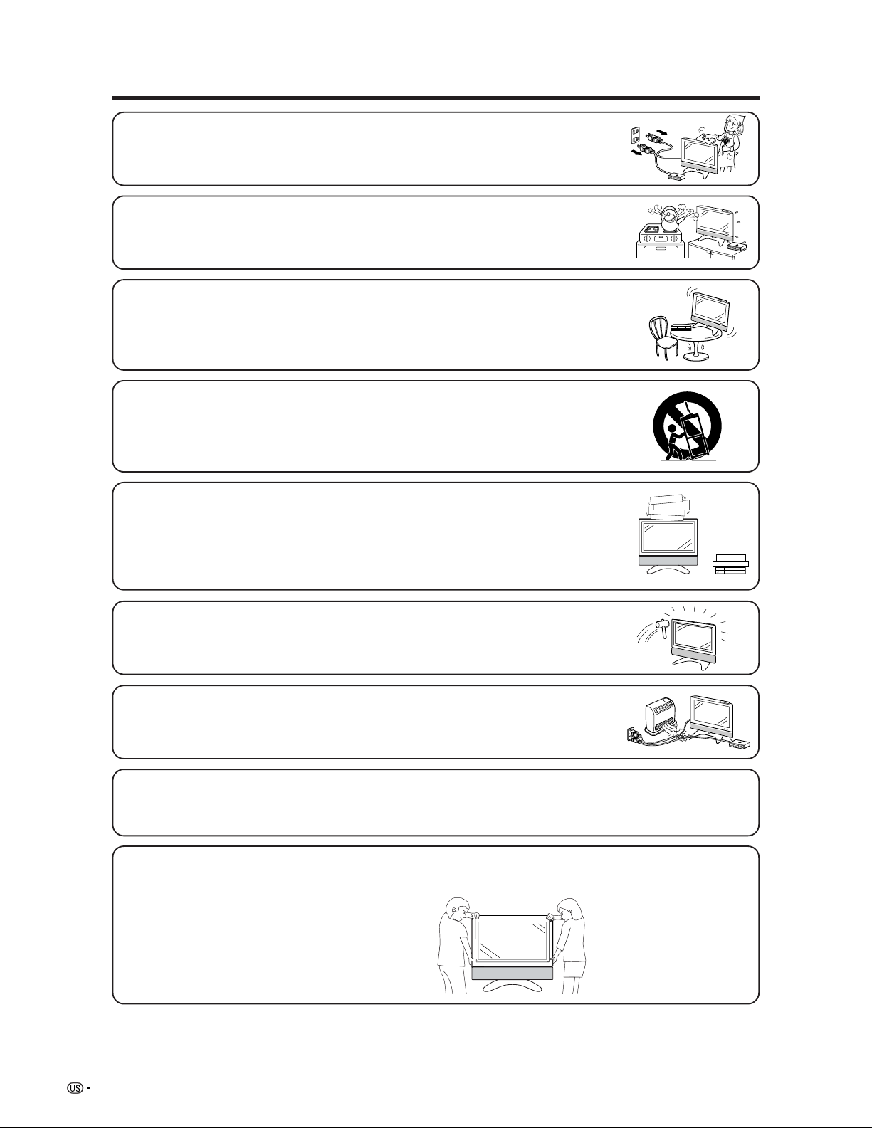
Precautions when transporting the Display
When transporting the Display, never carry it by holding onto the speaker. Be sure to always carry the Display by two
people holding it with two hands—one hand on each side of the Display.
• Heat — The product should be situated away from heat sources such as radiators, heat
registers, stoves, or other products (including amplifiers) that produce heat.
• A product and cart combination should be moved with care. Quick stops, excessive force,
and uneven surfaces may cause the product and cart combination to overturn.
5
IMPORTANT SAFETY PRECAUTIONS
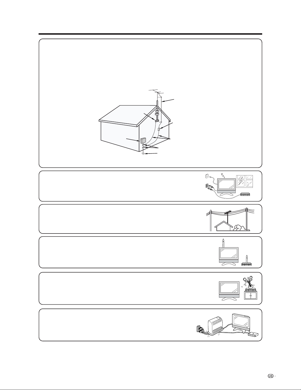
• Outdoor Antenna Grounding — If an outside antenna is connected to the television equipment, be sure the antenna
system is grounded so as to provide some protection against voltage surges and built-up static charges.
Article 810 of the National Electrical Code, ANSI/NFPA 70, provides information with regard to proper grounding of
the mast and supporting structure, grounding of the lead-in wire to an antenna discharge unit, size of grounding
conductors, Iocation of antenna-discharge unit, connection to grounding electrodes, and requirements for the
grounding electrode.
EXAMPLE OF ANTENNA GROUNDING AS PER
NATIONAL ELECTRICAL CODE, ANSI/NFPA 70
ANTENNA
LEAD IN
WIRE
ANTENNA
DISCHARGE UNIT
(NEC SECTION 810-20)
GROUNDING CONDUCTORS
(NEC SECTION 810-21)
GROUND CLAMPS
POWER SERVICE GROUNDING
ELECTRODE SYSTEM
(NEC ART 250, PART H)
GROUND
CLAMP
ELECTRIC
SERVICE
EQUIPMENT
NEC —NATIONAL ELECTRICAL CODE
• Lightning — For added protection for this television equipment during a lightning
storm, or when it is left unattended and unused for long periods of time, unplug it
from the wall outlet and disconnect the antenna. This will prevent damage to the
equipment due to lightning and power-line surges.
• Power Lines — An outside antenna system should not be located in the vicinity of
overhead power lines or other electric light or power circuits, or where it can fall
into such power lines or circuits. When installing an outside antenna system, extreme
care should be taken to keep from touching such power lines or circuits as contact
with them might be fatal.
• To prevent fire, never place any type of candle or naked flames on the top or near
the TV set.
• To prevent fire or shock hazard, do not expose this product to dripping or splashing.
No objects filled with liquids, such as vases, should be placed on the product.
• To prevent fire or shock hazard, do not place the AC power cord under the TV set
or other heavy items.

6
Contents
IMPORTANT INFORMATION ………………………1
Trademarks …………………………………………… 2
DEAR SHARP CUSTOMER …………………………3
IMPORTANT SAFETY PRECAUTIONS ……………3
Contents ……………………………………………… 6
Supplied accessories ………………………………7
Preparation …………………………………………… 8
Where to place the System ……………………… 8
Setting the System ……………………………… 9
Setting the AVC System with the stand ……… 11
Setting the Display on the wall ……………… 11
Removing the stand and speaker …………… 12
Inserting the batteries ………………………… 13
Using the remote control unit ………………… 13
Cautions regarding remote control unit … 13
Part names ………………………………………… 14
Display ………………………………………… 14
AVC System …………………………………… 15
Remote control unit …………………………… 16
Watching TV ……………………………………… 17
Antennas ……………………………………… 17
Cable converter/VCR connection …………… 17
Outdoor antenna connection ………………… 19
Connecting the AC cord ……………………… 20
Turning on the power ………………………… 21
Turning off the power ………………………… 21
Initial setup ……………………………………… 22
Simple button operations
for changing channels …………………… 23
Simple button operations
for changing volume/sound ……………… 24
Setting MTS/SAP stereo mode ……………… 25
Basic adjustment settings ……………………… 26
AV input mode menu items …………………… 26
PC input mode menu items …………………… 26
EZ setup ………………………………………… 27
Channel setup ………………………………… 28
Language setting ……………………………… 31
OPC setting …………………………………… 32
Picture adjustments …………………………… 33
C.M.S. (Color Management System) …… 34
Color temperature ………………………… 35
Black ……………………………………… 35
3D-Y/C ……………………………………… 36
Monochrome ……………………………… 36
Film mode (3:2 pull-down) ……………… 37
I/P Setting ………………………………… 37
Sound adjustment ……………………………… 38
Dolby virtual …………………………………… 38
Power control …………………………………… 39
Power control for AV source ……………… 39
Power control for PC source……………… 40
Using external equipment ……………………… 41
Watching a DVD image ……………………… 42
Connecting a DVD player ………………… 42
Displaying a DVD image ………………… 42
Watching a VCR image ……………………… 43
Connecting a VCR ………………………… 43
Displaying a VCR image ………………… 43
Watching broadcasts via a Digital TV tuner … 44
Connecting a Digital TV tuner …………… 44
Displaying broadcasts
via a Digital TV tuner ………………… 44
Enjoying a game console
or viewing camcorder images …………… 45
Connecting a game console
or camcorder ………………………… 45
Displaying an image of the game
console or camcorder ……………… 45
Viewing an image from a PC ………………… 46
Connecting a PC ………………………… 46
Displaying an image from a PC ………… 46
Useful adjustment settings ……………………… 47
Image position (AV input mode only) ……… 47
Moving the picture on the screen …………… 48
Connecting external speakers ……………… 49
Selecting speakers ……………………… 50
Auto Sync. adjustment (PC input mode only) … 51
Fine Sync. adjustment (PC input mode only) … 51
Input signal source …………………………… 52
Selecting Stretch Mode display
(AV input mode only) ……………………… 53
Picture flip ……………………………………… 54
AV MODE ……………………………………… 55
View mode for 4:3 Programs ………………… 55
View mode (for PC input mode) ……………… 56
Input signal (for PC input mode) …………… 57
DNR (Digital Noise Reduction) ……………… 57
Audio only ……………………………………… 58
Audio out ……………………………………… 58
Quick shoot …………………………………… 59
Sleep timer ……………………………………… 59
Closed caption ………………………………… 60
Secret number setting for parental control
(AV input mode only) ……………………… 61
Parental control (setting V-CHIP level) ……… 63
How to temporarily release
the V-CHIP BLOCK ……………………… 67
Reactivating the temporarily released
the V-CHIP BLOCK ……………………… 67
Other viewing options …………………………… 68
Twin picture functions ………………………… 68
Learning remote control function …………… 69
Using the TV remote control unit
to control other devices…………………… 71
Appendix ………………………………………… 77
Troubleshooting ………………………………… 77
PC compatibility chart ………………………… 78
RS-232C port specifications ………………… 79
Specifications ………………………………… 81
Optional accessories ………………………… 81
Dimensional drawings …………………………… 82
7
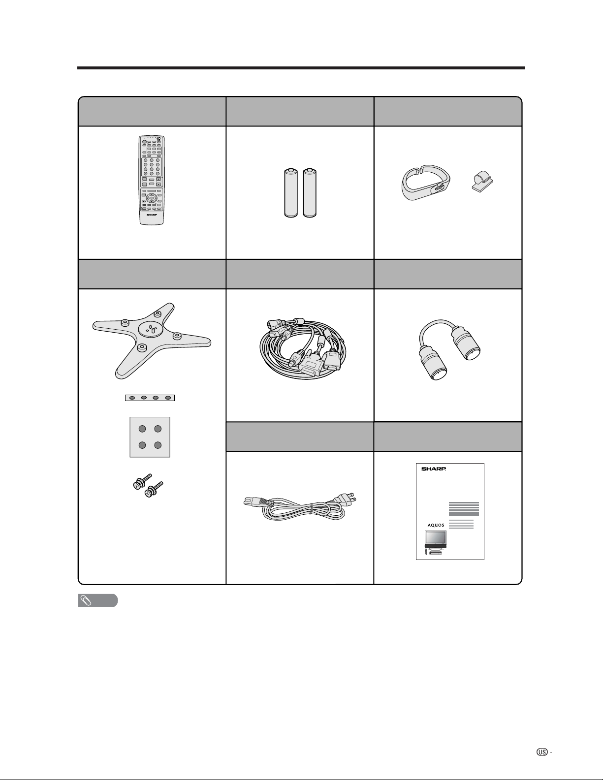
Supplied accessories
Make sure the following accessories are provided with the product.
LC-30HV6U
Remote control unit (g1) “AA” size battery (g2)
Stand unit (for AVC System) (g1) System cable (g1)
QACCD3097CEPZ
Cable clamp (Large g1, Small g1)
Operation manual (g1)AC cord (g2)
RRMCGA203WJSA
Page 13 Page 13
LHLDW0110CEZZ (Large)
LHLDZ0139CEZZ (Small)
Page 10
QCNW-B855WJZZ
Page 9
Page 9
Stand (g1)
Stand cushion (g4)
Stand spacer (g4)
Stand screw (g2)
Page 11
TV
ANT-A/B
INPUT
TWIN
MODE
AV
POWER
MTS CC
PICTURE
SELECT
SUB TWIN CH
ⴐ
ⴑ
FREEZE
MODE
VOL CH
MUTE
MENU TV/SAT/DVD
FAVORITE CH
RECEIVER
DTV/DVD TOP
SOURCE DTV/SAT
DTV/SAT
VCR REC
ABCD
RETURN
MENU
POWER
SET/
ENTER
MENU
GUIDE
INPUTPOWER VOL
ⴑ
VOL
ⴐ
INFO
VIEW
SLEEP LEARN
EDIT/
ENT
DISPLAY
INPUT
TV VCRCBL
/SAT
/DTV
DVD
/LD
123
456
789
100
0
FLASHBACK
Virtual
RF cable (g1)
TINS-A929WJZZ
QCNW-A342WJZZ
Pages 18 and 19
GDAI-A059WJSA
PSPAHA101WJZZ
GLEGGA013WJZZ
XBPSN40P14JS0
NOTE
• Always use the AC cord supplied with the Liquid Crystal Television and the one supplied with the AVC System for each
respective unit.
• AC cords enclosed in this product are for 110-125V. In using it on the 125-240V AC, please consult to the following.
SHARP ELECTRONICS CORPORATION
1300 Naperville Drive, Romeoville, Illinois 60446-1091, U.S.A. TEL: 630-226-2400
8
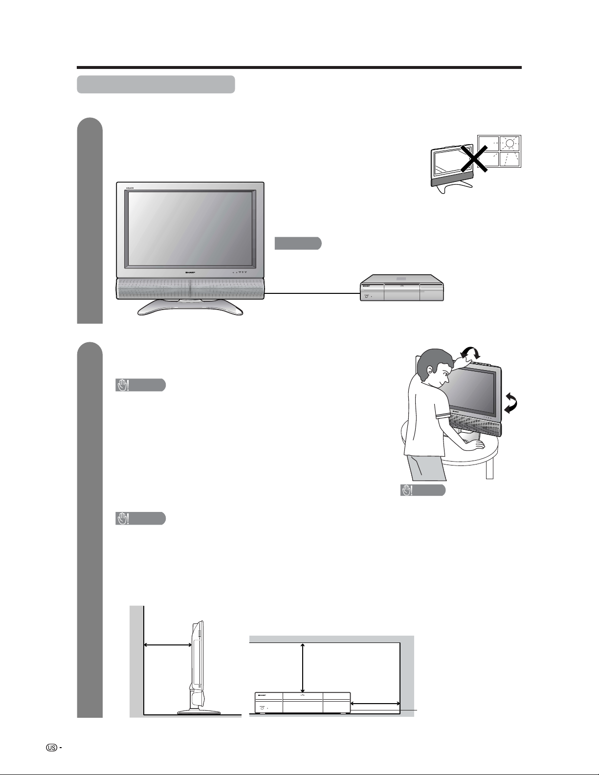
Setting the System in place
Handling the Display
CAUTION
• When using the TV with the supplied stand attached, do not
remove the speaker. Doing so may disturb the balance
leading to product damage or personal injury.
• Do not remove the stand and speaker from the Display unless
using an optional bracket to mount it.
• Keep enough space above and behind the Display.
• The Display is heavy. Move it with two or more people.
• When you move the Display, hold the portion of the Display, not
the speaker.
Handling the AVC System
CAUTION
• Do not put a VCR or other device on the AVC System.
• Keep enough space above and on the sides of the AVC System.
• Do not block the ventilation openings on the top and left side,
and the exhaust fan on the right side.
• Do not spread a thick cloth beneath the AVC System, or cover it
with one, as this can cause overheating and result in malfunction.
Where to place the System
“System” means the Display and AVC System. First select the location where to place the System.
Selecting the location of the System
• Select a place with no direct sunlight and good ventilation.
• The Display and the AVC System are connected by the system cable.
(See page 9 for details.)
Keep enough space
System cable
AVC System
Display
There is an
exhaust fan on
the right side.
1
2
4 inches
(10 cm)
or more
2 inches
(5 cm) or more
2 inches
(5 cm) or
more
Preparation
If you want to keep a longer distance between the Display and AVC
System, please purchase the optional system cable AN-07SC1
(about 23 feet/7 meters). (See page 81.)
IMPORTANT
• You cannot use external speakers when you are using the optional
system cable (AN-07SC1).
CAUTION
Adjust the screen with both
hands. Put one hand on the
Display and tilt the screen
while steadying the stand
with your other hand.
You can adjust the screen
vertically up to 4 degrees
forward or 6 degrees back-
ward, or rotate 10 degrees
horizontally.
9
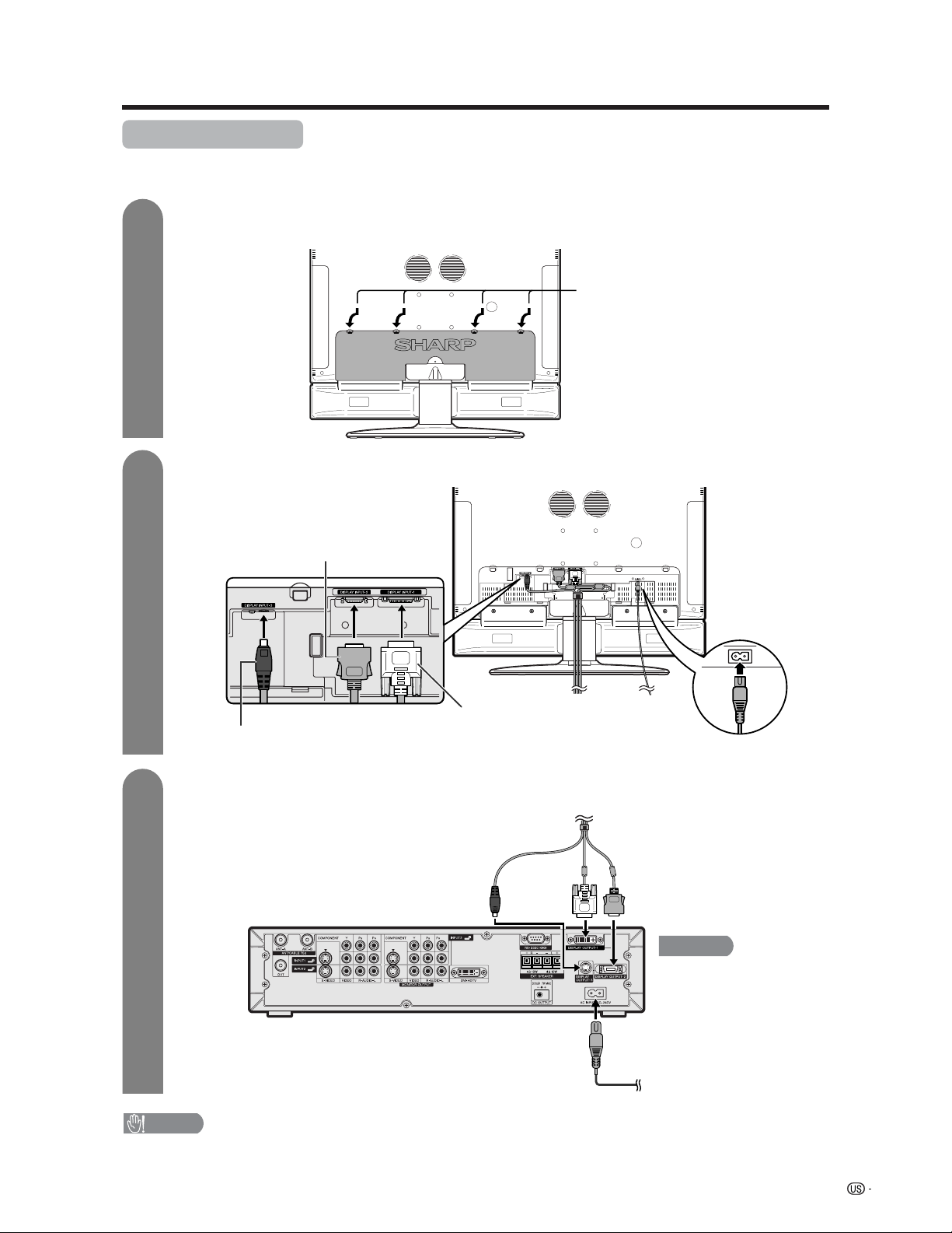
System cable
AVC System (rear view)
AC cord
Display (rear view)
Setting the System
After putting the Display and the AVC System in place, connect the system cables and AC cords. Use the
cable clamps for bundling the cables.
Preparation
Connecting the system cable and the AC cord to the Display
1
2
3
Removing the terminal cover
Connecting the system cable and the AC cord to the AVC System
CAUTION
• TO PREVENT RISK OF ELECTRIC SHOCK, DO NOT TOUCH UN-INSULATED PARTS OF ANY CABLES WITH THE
AC CORD CONNECTED.
Press down the four
upper hooks to remove
the cover toward you.
AC cord
(GRAY)
Connect the plug firmly until
the hooks on both sides click.
(WHITE)
Connect the plug into the
terminal and secure it by
tightening the thumb screws.
(BLACK)
Connect the plug completely.
(BLACK) (WHITE) (GRAY)
You cannot use external
speakers when you are using
the optional system cable
(AN-07SC1).
IMPORTANT
System cable
10
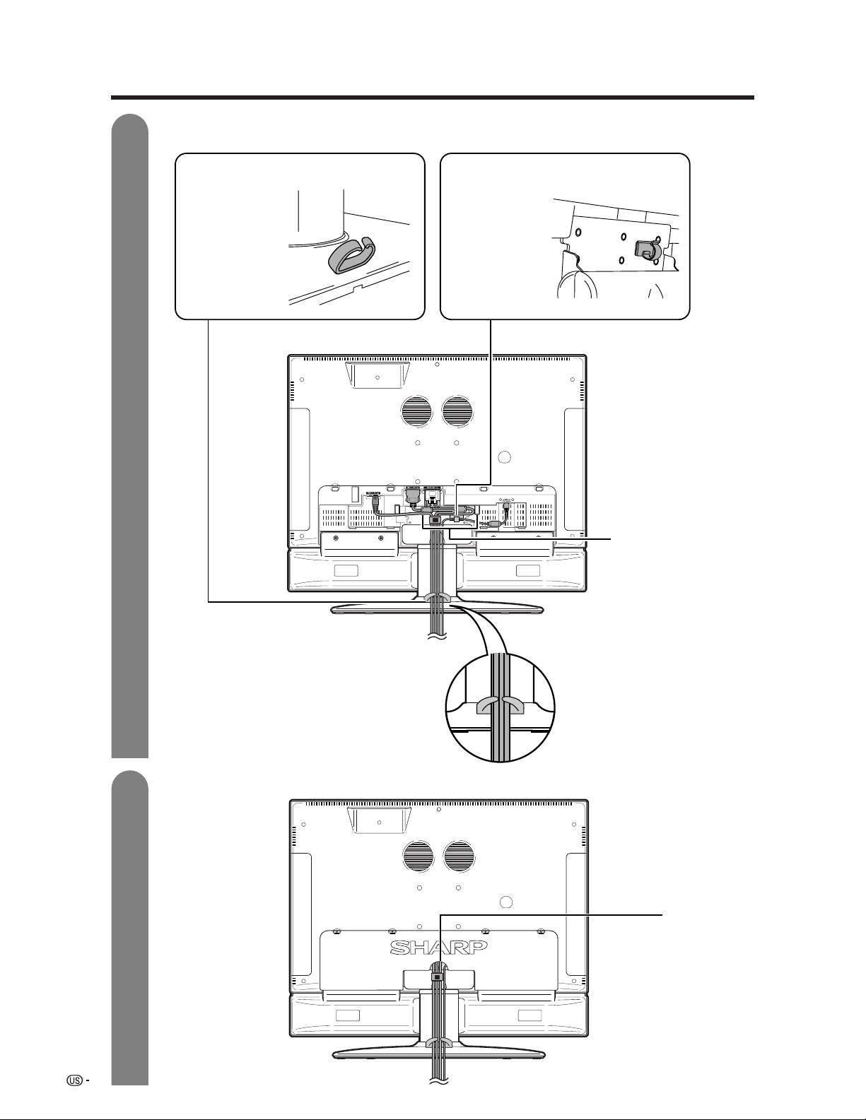
Preparation
4
5
Attaching the clamps and bundling the cables with the clamp
Closing the terminal cover
Cable clamp (Large)
Insert the cable
clamp in the hole
on the Display leg
as shown.
Cable clamp (Small)
Peel off the seal
on the back and
attach as shown.
Display (rear view)
Cables come
out from the
small opening.
Arrange the system
cable as shown in
the illustration.
11
Preparation
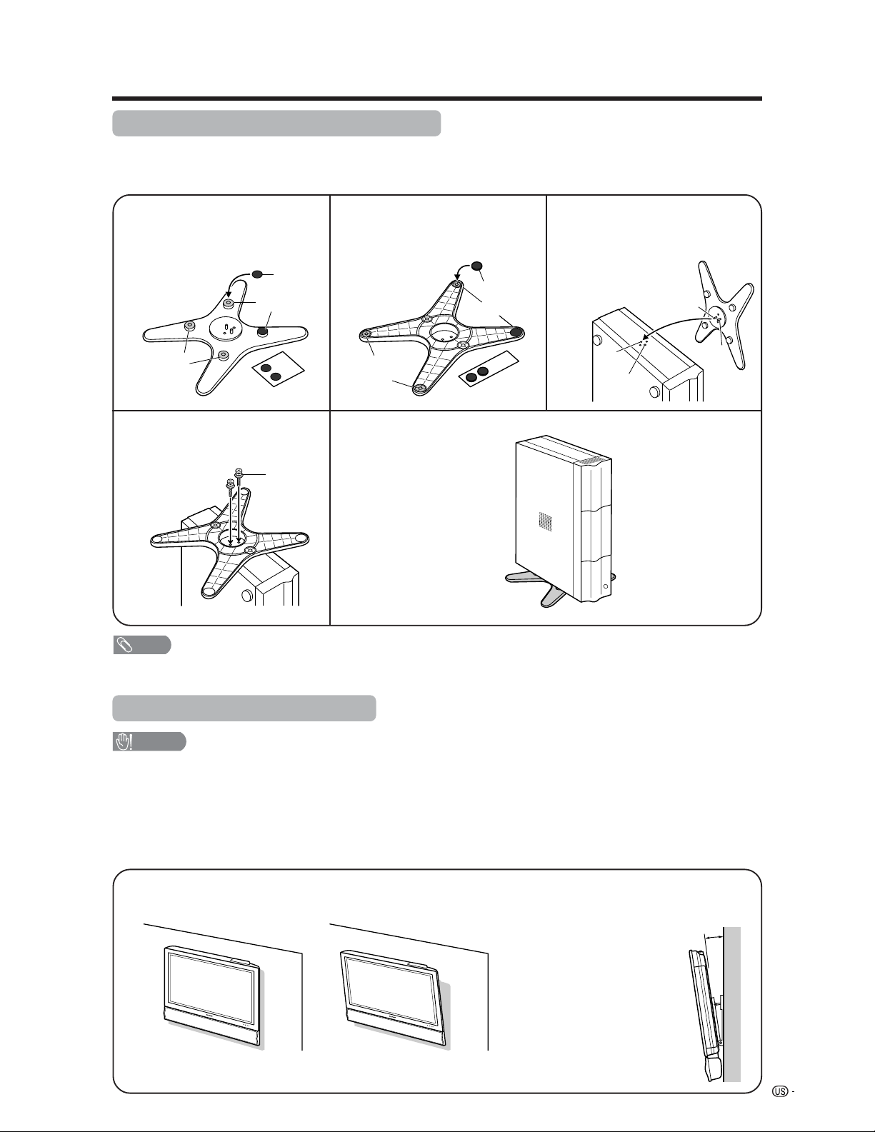
Setting the Display on the wall
CAUTION
• Installing the Liquid Crystal Television requires special skill that should only be performed by qualified service
personnel. Customers should not attempt to do the work themselves. SHARP bears no responsibility for improper
mounting or mounting that results in accident or injury.
Using an optional bracket to mount the Display
• You can ask a qualified service personnel about using an optional AN-37AG1 bracket to mount the Display
to the wall.
• Carefully read the instructions that come with the bracket before beginning work.
Vertical mounting Angular mounting
Hanging on the wall
AN-37AG1 wall mount bracket. (See the bracket instructions for details.)
Setting the AVC System with the stand
1
How to install the AVC System vertically using the stand unit.
• Use the supplied stand unit for installing the AVC System vertically in an upright position.
Stick each spacer to the
stand as shown.
Peel each spacer
away from the
paper and attach
to the four bulging
areas on the stand.
2
Attach each cushion to
the stand as shown.
3
Fit the stand to the AVC
System.
Peel each cushion
away from the
paper and attach
to the four areas at
the bottom.
Insert the stand into the AVC
System, making sure that the
thick and thin bulges of the
stand align with the big and
small holes on the AVC
System.
Stand
spacer
Bulge
Stand cushion
Thin bulge
Thick
bulge
Big hole
Small
hole
4
Attach the stand using the
stand screws as shown.
Stand screw
The AVC System installed
vertically with the stand.
NOTE
• When mounting the AVC System vertically, always use the supplied stand. Be careful not to block vent holes when
standing up directly on the floor or a flat surface as this can result in equipment failure.
Attaching point
Attaching point
Bulge
5°
About setting the Display angle
• You can set the Display on the
wall up to 5 degrees forward
when the speaker is attached and
up to 20 degrees forward when
the speaker is not attached. Do
not set the angle outside those
ranges.
12
Preparation
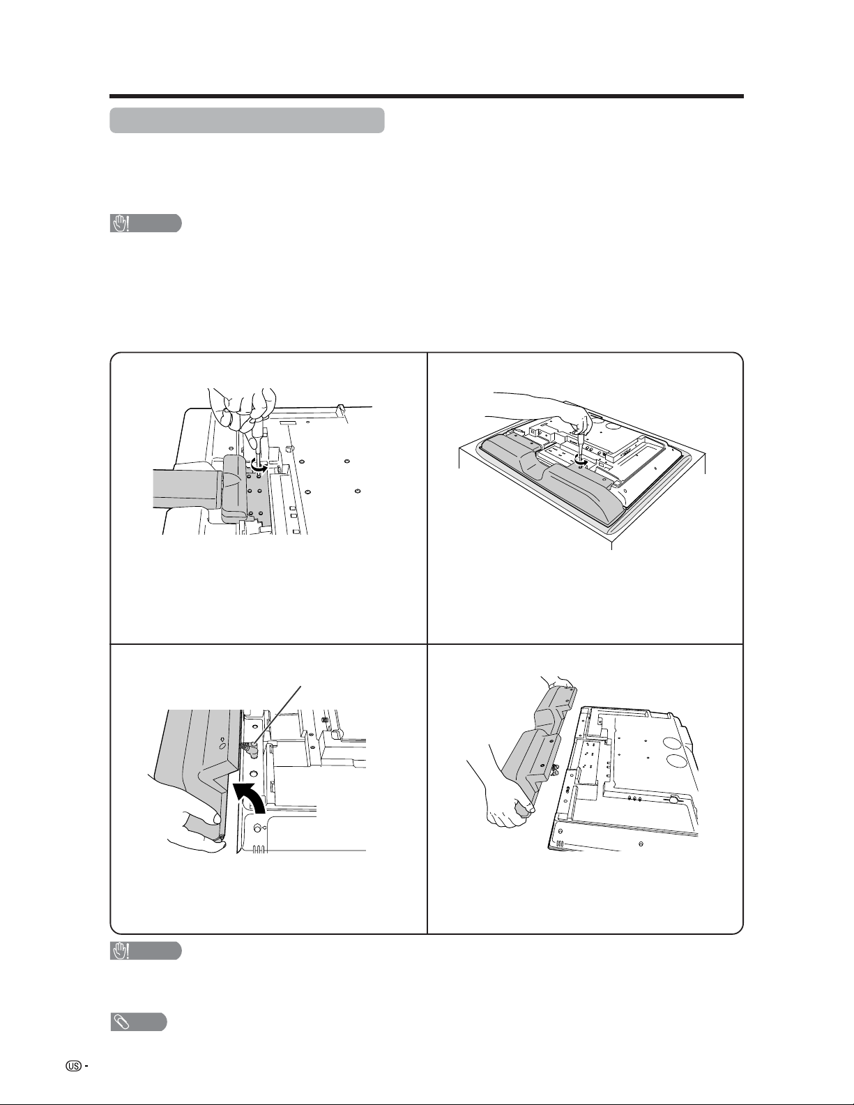
Removing the stand and speaker
This unit has a detachable type speaker.
You can detach the system speaker when using external speakers.
Before detaching (or attaching) speaker, unplug the AC cord from the AC outlet and the system cable from the
Display.
CAUTION
• Do not remove the stand and speaker from the Display unless using an optional bracket to mount it.
• When using the TV with the supplied stand attached, do not remove the speaker. Doing so may disturb
the balance leading to product damage or personal injury.
Before attaching/detaching speaker
• Before performing work make sure to turn off the System.
• Before performing work spread cushioning over the base area to lay the Display on. This will prevent it from
being damaged.
CAUTION
• The speaker terminals on the Display are only for the attached speaker. Do not connect any third party plug or speaker
to the terminal.
• Insert the speaker plug completely into the terminal.
NOTE
• To attach the speaker, perform the above steps in reverse order. Check the left (L) and right (R) when connecting the
speaker plugs.
2
34
Unfasten the four screws used to secure the
speaker in place.
Take hold of the speaker and slowly slide it
sideways.
(The speaker plugs are still inserted, so make
sure not to pull the speaker too far.)
Remove the two speaker plugs from the terminal
on the Display.
(Do not remove the plugs by pulling the cord.)
Now the speaker can be detached from the Display.
Speaker plug
1
Unfasten the six screws used to secure the
stand in place, and then detach the stand from
the Display.
(Hold the stand so it will not drop from the edge
of the base area.)
13
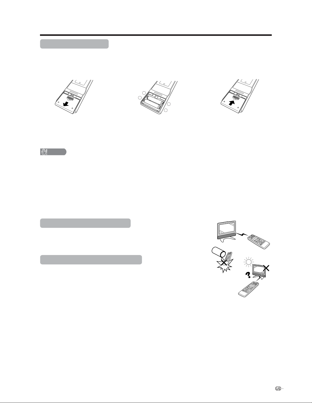
+
+
_
_
1 Open the battery cover. 2 Insert two “AA” size batteries
(supplied with the product).
• Place the batteries with their terminals
corresponding to the (e) and (f)
indications in the battery compartment.
3 Close the battery cover.
CAUTION
Improper use of batteries can result in chemical leakage or explosion. Be sure to follow the instructions below.
• Place the batteries with their terminals corresponding to the (e) and (f) indications.
• Do not mix batteries of different types. Different types of batteries have different characteristics.
• Do not mix old and new batteries. Mixing old and new batteries can shorten the life of new batteries or cause
chemical leakage in old batteries.
• Remove batteries as soon as they are worn out. Chemicals that leak from batteries can cause a rash. If you
find any chemical leakage, wipe thoroughly with a cloth.
• The batteries supplied with this product may have a shorter life expectancy due to storage conditions.
• If you will not be using the remote control unit for an extended period of time, remove batteries from it.
Inserting the batteries
If the remote control fails to operate Liquid Crystal Television functions, replace the batteries in the remote
control unit.
Using the remote control unit
Use the remote control unit by pointing it towards the remote control sensor on
the Display. Objects between the remote control unit and the remote control
sensor may prevent proper operation.
Cautions regarding remote control unit
• Do not expose the remote control unit to shock.
In addition, do not expose the remote control unit to liquids, and do not place
in an area with high humidity.
• Do not install or place the remote control unit under direct sunlight.
The heat may cause deformation of the remote control unit.
• The remote control unit may not work properly if the remote control sensor on
the Display is under direct sunlight or strong lighting. In such cases, change
the angle of the lighting or the Display, or operate the remote control unit
closer to the remote control sensor.
Preparation
14
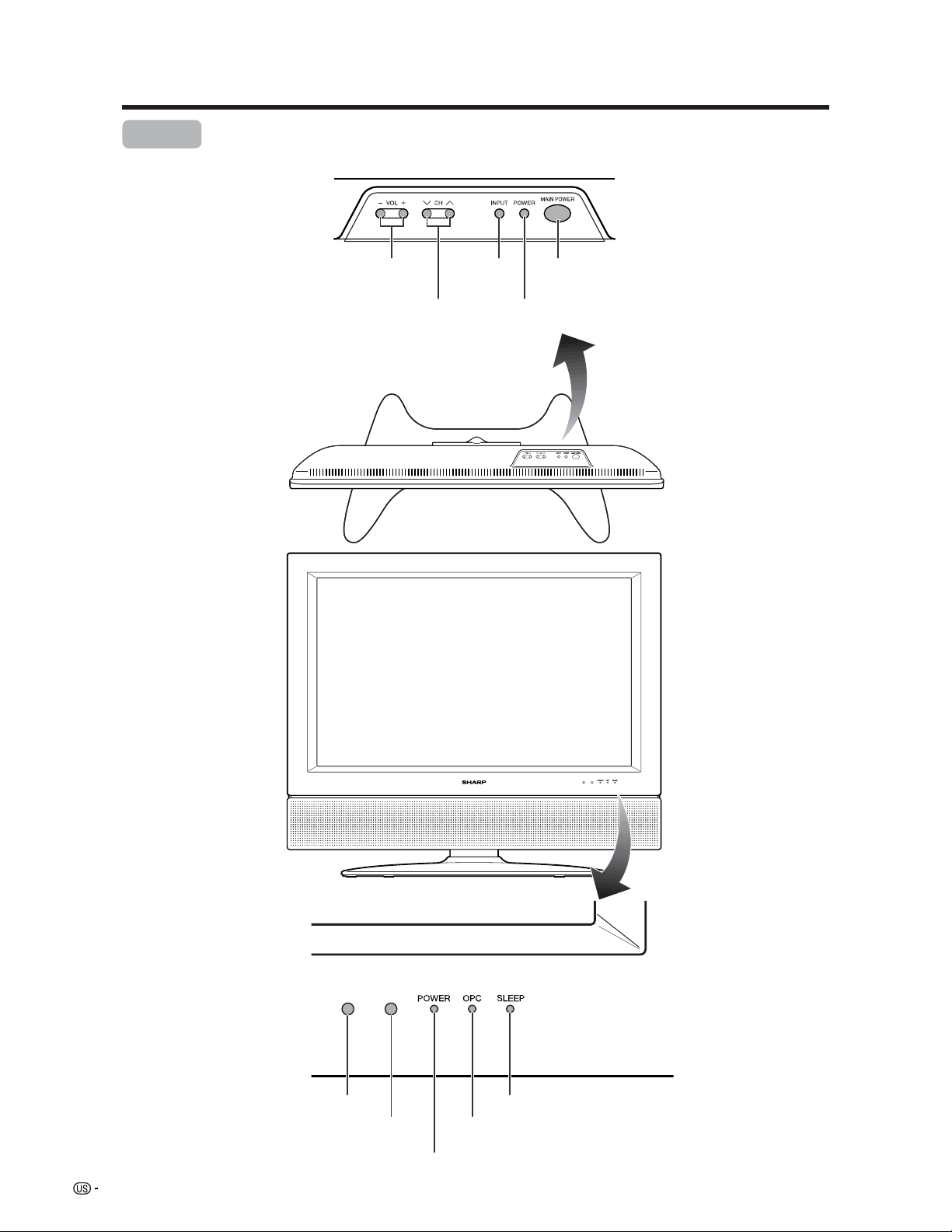
Part names
OPC indicator*
POWER indicator
MAIN POWER
button
OPC sensor
Display
POWER button
INPUT
button
VOLUME buttons
(VOLl/k )
CHANNEL buttons
(CHs/r)
Remote control sensor
*OPC: Optical Picture Control
(See page 32.)
SLEEP indicator
15
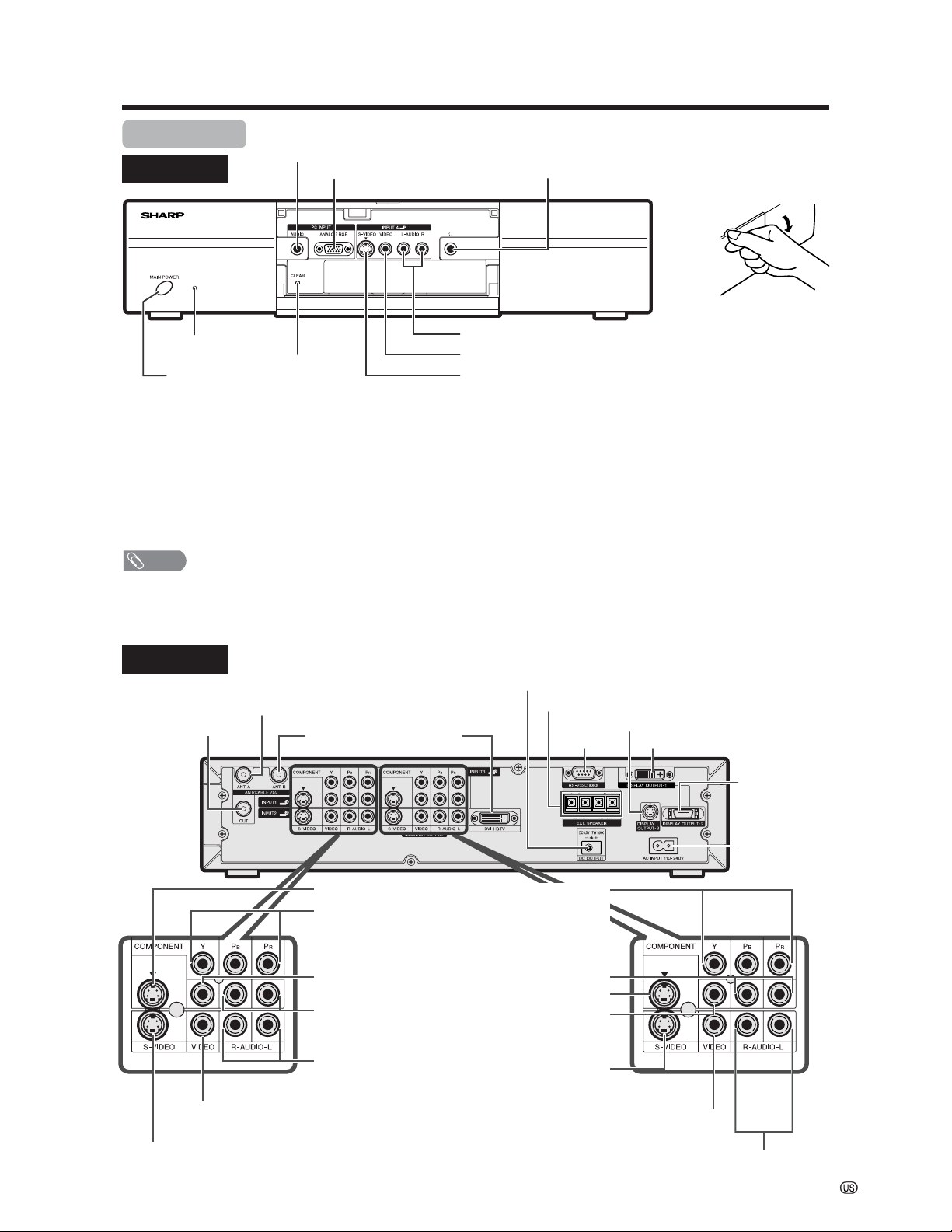
Part names
Front view
CLEAR*
MAIN POWER button
INPUT 4 terminal (S-VIDEO)
INPUT 4 terminal (VIDEO)
PC INPUT terminal (AUDIO)
INPUT 4 terminals (AUDIO L/R)
PC INPUT terminal (ANALOG RGB)
AVC System
Rear view
INPUT 1 COMPONENT
video terminals (Y, PB, PR)
INPUT 3 COMPONENT
video terminals (Y, P
B, PR)
MONITOR OUTPUT terminal
(S-VIDEO)
DISPLAY OUTPUT 1 terminal
DISPLAY
OUTPUT 2
terminal
AC INPUT
terminal
RS-232C
terminal
MONITOR OUTPUT terminals (AUDIO L/R)
Antenna (A) input terminal
Antenna (B)
input terminal
Antenna (A) output
terminal
DVI-HDTV
INPUT
terminal
INPUT 3 terminal (S-VIDEO)
INPUT 3 terminal (VIDEO)
INPUT 3 terminals (AUDIO L/R)
INPUT 1 terminal (S-VIDEO)
INPUT 1 terminal
(VIDEO)
INPUT 1 terminals
(AUDIO L/R)
INPUT 2 terminal (S-VIDEO)
INPUT 2 terminal (VIDEO)
INPUT 2 terminals
(AUDIO L/R)
How to open the door.
STANDBY/ON indicator
* If the AVC System is switched on but it does not appear to be operating correctly, it may need resetting. In this
case, press CLEAR, shown in the diagram, lightly with the end of a ballpoint pen or other pointed object.
This will reset the System as shown below.
• AV MODE resets to STANDARD
• TV channel returns to initial channel setting (Air:2ch, Cable:1 or 2ch)
• Twin picture resets to normal
• Audio setting initializes
• Dolby virtual resets to Off
• Image position initializes
NOTE
• Pressing CLEAR will not work if the System is in standby mode (indicator lights red).
• Pressing CLEAR will not delete channel preset or secret number. See page 62 for clearing the secret number when you
know it. See page 84 for initializing to the factory preset values when you forget your secret number.
Headphone
(When connecting headphones, the sound from the
speakers is muted.)
DC OUTPUT terminal
(Terminal for expanded functionality in
the near future.)
MONITOR OUTPUT terminal
(VIDEO)
DISPLAY OUTPUT 3 terminal
EXTERNAL SPEAKER terminals
16
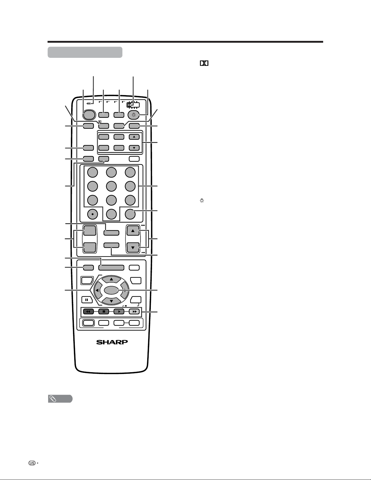
Part names
Remote control unit
NOTE
• When using the remote control unit, point it at the Liquid
Crystal Television.
• See pages 69 to 76 for operating buttons not listed on
this page.
TV
ANT-A/B
INPUT
Virtual
TWIN
MODE
AV
POWER
MTS CC
PICTURE
SELECT
SUB TWIN CH
ⴐ
ⴑ
FREEZE
MODE
VOL CH
MUTE
MENU TV/SAT/DVD
FAVORITE CH
RECEIVER
DTV/DVD TOP
SOURCE DTV/SAT
DTV/SAT
VCR REC
ABCD
RETURN
MENU
POWER
SET/
ENTER
MENU
GUIDE
INPUT VOL
ⴑ
VOL
ⴐ
INFO
VIEW
SLEEP LEARN
EDIT/
ENT
FLASHBACK
DISPLAY
INPUT
TV VCRCBL
/SAT
/DTV
DVD
/LD
123
456
789
100
0
POWER
16
17
18
19
20
21
22
24 25
23
3
2
1
4
5
6
7
8
9
10
11
12 13
14
15
1 TV POWER: Switch the Liquid Crystal Television power
on or off. (See page 21.)
2
Virtual: Select Virtual Dolby Surround settings. (See
page 24.)
3 AV MODE: Select an audio or video setting. (See
page 55.) (AV mode: STANDARD, MOVIE, GAME,
USER, DYNAMIC (Fixed), DYNAMIC. PC mode:
STANDARD, USER.)
4 VIEW MODE: Select the screen size. (See pages 55
and 56.)
5 DISPLAY: Display the channel information.
6 SLEEP: Set the sleep timer. (See page 59.)
7 FLASHBACK: Return to the previous channel or input
external mode. (See page 23.)
8VOL
kk
kk
k/
ll
ll
l: Set the volume. (See page 24.)
9 MENU: Display the menu screen.
10 MENU RETURN: Return to the previous menu screen.
11 a/b/c/d: Select a desired item on the screen.
12 ANT-A/B: Select between ANT-A and B to watch
broadcasts via the two tuners.
13 INPUT: Select a Liquid Crystal Television input source.
(TV, INPUT 1, INPUT 2, INPUT 3, INPUT 4, PC) (See
pages 42–46 and 52.)
14
: When pressed all buttons on the remote control unit
will light. The lighting will turn off if no operations are
performed within about 5 seconds. This button is used
for performing operations in dark places.
15 MTS: Select the MTS/SAP. (See page 25.)
16 CC: Display captions during closed-caption source.
(See page 60.)
17 TWIN CH buttons
TWIN PICTURE: Set the twin picture mode.
Press again to return to normal screen. (See page
68.)
FREEZE: Set the still image. Press again to return to
normal screen. (See page 68.)
SELECT: Select the active screen. (See page 68.)
SUB INPUT: Select an input source of sub screen.
(See page 68.)
TWIN CH a/b: Select the channel of sub screen.
(See page 68.)
18 0 – 9: Set the channel.
19 100 ENT: Select the three digit mode. Execute a
command of the channel.
20 CH
aa
aa
a/
bb
bb
b: Select the channel.
21 MUTE: Mute the sound. (See page 24.)
22 SET/ENTER: Execute a command.
23 FAVORITE CH
A, B, C, D: Select four preset favorite channels in four
different categories. (See page 30 for details.)
When viewing via ANT-A: up to 16 channels can be
assigned in A, B, C and D.
When viewing via ANT-B: up to 16 channels can be
assigned in A, B, C and D.
With ANT-A and B combined, you can preset up to 32
favorite channels in advance.
While watching, you can toggle the selected channels
by pressing A, B, C and D.
24 LED for transmission confirmation
25 Mode switch: (See pages 69 to 76 for details.)
17
Watching TV
Simple operations for watching a TV program
Antennas
To enjoy a clearer picture, use an outdoor antenna. The following is a brief explanation of the types of connections
that are used for a coaxial cable. If your outdoor antenna uses a 75-ohm coaxial cable with an F-type connector,
plug it into the antenna terminal at the rear of the AVC System.
NOTE
• The antenna and the cable converter cannot be connected at the same time.
1. A 75-ohm system is generally a round cable with F-type
connector that can easily be attached to a terminal without
tools (not supplied).
2. A 300-ohm system is a flat “twin-lead” cable that can be
attached to a 75-ohm terminal through a 300/75-ohm
adapter (not supplied).
F-type connector
75-ohm coaxial cable (round)
300-ohm twin-lead cable (flat)
• Be sure to connect the antenna or the cable converter as follows. Signal reception may fail if improperly connected.
• Be sure to remember what kind of connection is made with your System.
• The connection type will determine whether to select “Air” or “Cable” for both ANT-A and B when configuring “Air/Cable”
settings.
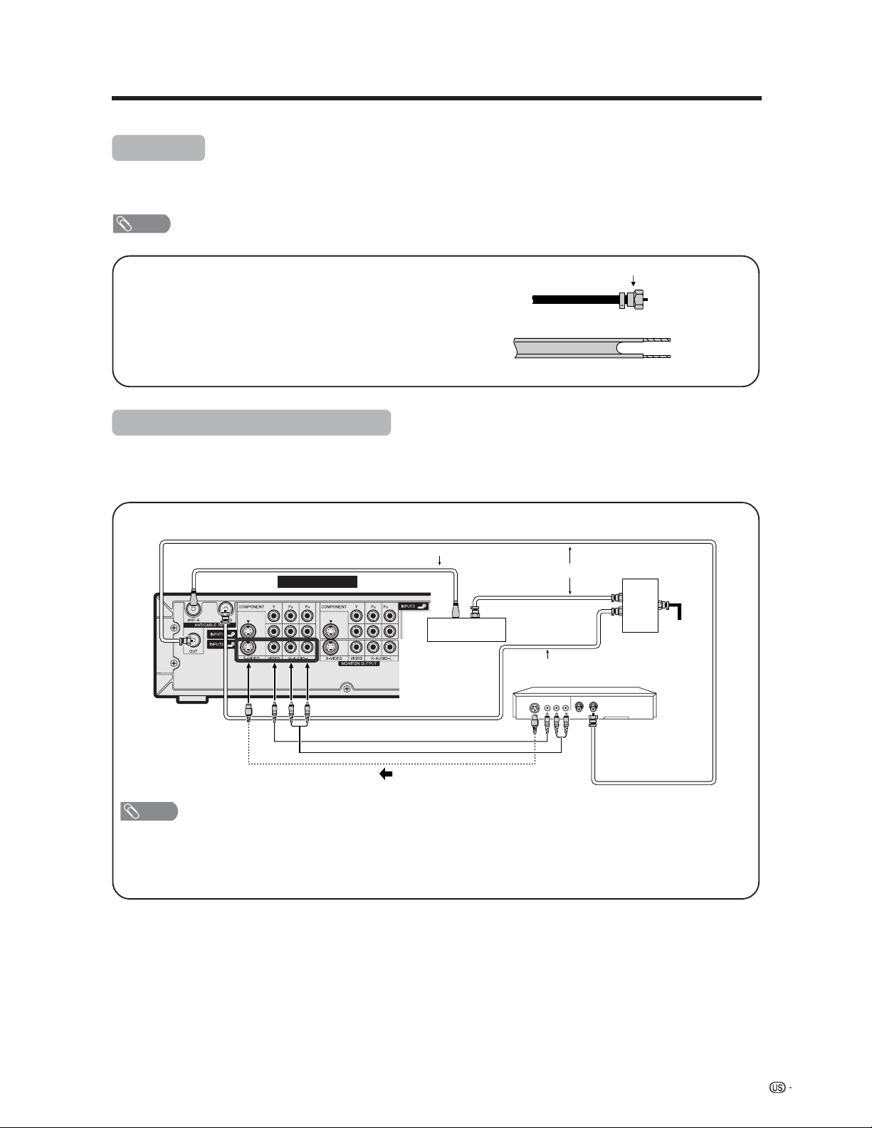
Cable converter/VCR connection
S-VIDEO
Coaxial Antenna Cable (commercially available)
VCR
Video Cable (commercially available)
Audio Cable (commercially available)
S-video Cable (commercially available)
Coaxial Antenna Cable (commercially available)
Cable lead-in
Cable TV converter
(not supplied)
OUT IN
2-way
signal
splitter
(not
supplied)
VIDEO AUDIO OUT IN
Coaxial Antenna Cable (commercially available)
Rear Terminals
A-1. Connecting with Converter/Descrambler Box and VCR
NOTE
• Be sure to remember what kind of connection is made with your System.
• Shown here is the preferred method of connecting a VCR and CATV Converter to your TV if you are in an area with good
signal reception. This way you can view either TV programs or VCR tapes and not be concerned about the position of the
VCR’s TV/VCR switch and you can enjoy stereo tape playback from a stereo VCR.
• If your VCR has an S-Video terminal, S-video connection is recommended.
18
Watching TV
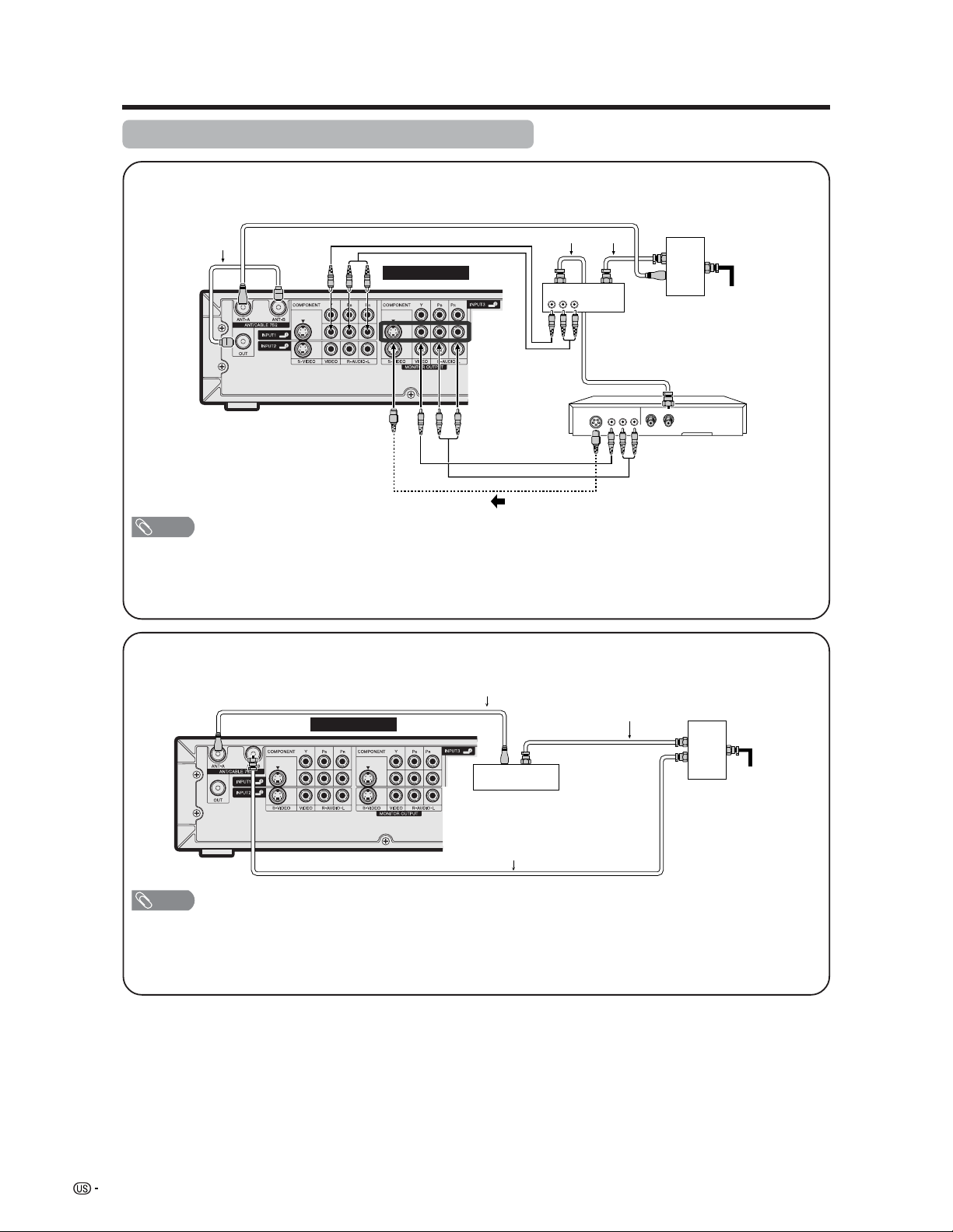
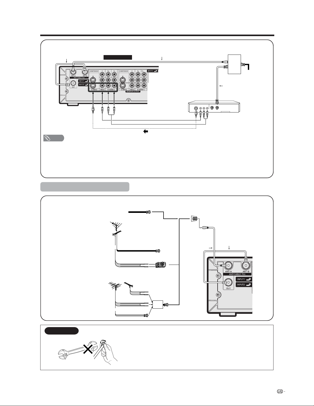
A-2. Connecting with cable converter using AUX terminals for audio and video output.
(If your cable TV converter has both RF OUTPUT and AUX terminals, it is recommended to connect it as
shown in example A-1.)
Rear Terminals
S-VIDEO
Coaxial Antenna Cable (commercially available)
VCR
Cable lead-in
OUT IN
VIDEO AUDIO OUT IN
RF
Cable
(Supplied)
VIDEO AUDIO
Cable TV converter
(not supplied)
Video Cable
(commercially available)
Audio Cable
(commercially available)
S-video Cable (commercially available)
2-way
signal
splitter
(not
supplied)
NOTE
• Be sure to remember what kind of connection is made with your System.
• Shown here is the preferred method of connecting a VCR and CATV Converter to your TV if you are in an area with good
signal reception. This way you can view either TV programs or VCR tapes and not be concerned about the position of the
VCR’s TV/VCR switch and you can enjoy stereo tape playback from a stereo VCR.
• If your VCR has an S-Video terminal, S-video connection is recommended.
B. Connecting with Converter/Descrambler Box without VCR
Coaxial Antenna Cable (commercially available)
Cable lead-in
OUT IN
Coaxial Antenna Cable (commercially available)
Coaxial Antenna Cable (commercially available)
Rear Terminals
2-way
signal
splitter
(not
supplied)
Cable TV converter
(not supplied)
NOTE
• Be sure to remember what kind of connection is made with your System.
• Switching between Antenna-A and Antenna-B is possible by pressing the ANT-A/B button on the remote control.
• A good color picture depends on a good TV signal. So does good multi-channel sound. Ask your dealer for advice on
how to install your outdoor antenna to receive the best possible signal.
• If you subscribe to Cable TV or have a central antenna for your building, you may not need an outdoor antenna.
Cable converter/VCR connection (continued)
19
Watching TV
C. Connecting Antenna Cable with VCR
NOTE
• Be sure to remember what kind of connection is made with your System.
• Shown here is the preferred method of connecting a VCR to your TV if you are in an area with good signal reception. This
way you can view either TV programs or VCR tapes and not be concerned about the position of the VCR’s TV/VCR switch
and you can enjoy stereo tape playback from stereo VCR.
• If your VCR has an S-Video terminal, S-video connection is recommended.
• If your lead cable is a 300-ohm twin-lead cable or UHF/VHF separate cable, use a 300/75-ohm adapter or combiner
(output side is 75-ohm coaxial) to connect to the TV (see below).
S-VIDEO
VCR
VIDEO AUDIO OUT IN
Coaxial Antenna Cable
(commercially available)
Video Cable (commercially available)
Audio Cable (commercially available)
S-video Cable (commercially available)
Cable lead-in
Coaxial Antenna Cable (commercially available)
Rear Terminals
RF Cable
(Supplied)
2-way
signal
splitter
(not
supplied)
300-ohm twin-lead (flat)
300-ohm twin-lead
75-ohm coaxial cable (round)
75-ohm coaxial cable
Cable TV lead-In
or
IN OUT
300-ohm
twin-lead
VHF
ANTENNA
UHF
ANTENNA
Combiner
(commercially
available)
or
Coaxial cable
(commercially
available)
Home Antenna
terminal (75-ohm)
300/75-ohm adapter
(commercially available)
RF Cable (Supplied)
Cable without a CATV
converter
Combination
VHF/UHF antenna
Separate VHF/UHF
antenna
Connecting Antenna Cable
Outdoor antenna connection
F-type connector
75-ohm coaxial cable
When connecting the RF cable to the TV set, do not tighten
F-type connector with tools.
If tools are used, it may cause damage to your TV set.
(The breaking of internal circuit, etc.)
F-type connector should be finger-tightened only.
NOTICE
20
Watching TV
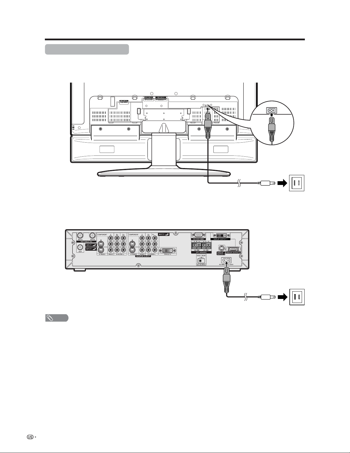
Connecting the AC cord
Connect the AC cords after all component connections have been completed.
Display (rear view)
AC cord
AC cord
AVC System (rear view)
NOTE
• Always turn off the main power of the Display and AVC System when connecting the AC cords.
• Disconnect the AC cords from the AC outlet, Display and AVC System when the System is not going to be used for a long
period of time.
21
Watching TV
Display
AVC System
POWER button
MODE
AV
TV
ANT-A/B
INPUT
TWIN
POWER
MTS CC
PICTURE
SELECT
SUB TWIN CH
FREEZE
MODE
VIEW
SLEEP LEARN
EDIT/
ENT
DISPLAY
INPUT
TV VCRCBL
/SAT
/DTV
DVD
/LD
123
456
789
100
0
Virtual
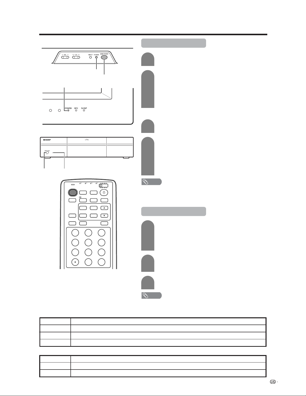
Turning on the power
STANDBY/ON indicatorMAIN
POWER
MAIN POWER
Off
Flashing red
Red
Green
Display status indicator
Power off
AVC System does not turn on or its AC cord is disconnected.
The System is in standby mode.
The System is on.
AVC System status indicator
Power off
Only the AVC System is in standby mode or the System is in standby mode.
The System is on.
Off
Red
Green
POWER indicator
1
2
3
Press MAIN POWER on the Display.
• The POWER indicator on the Display flashes red.
Press MAIN POWER on the AVC System.
• The System turns the power on.
• The POWER indicator on the Display lights up green and the
STANDBY/ON indicator on the AVC System lights up green.
• If the STANDBY/ON indicator on the AVC System and the POWER
indicator on the Display still light up red, press TV POWER on
the remote control unit or MAIN POWER on the AVC System to
turn the System on.
First time turning on the AVC System
Press MAIN POWER on the AVC System.
• The STANDBY/ON indicator on the AVC System lights up red.
1
2
Press MAIN POWER on the Display.
• The System turns the power on.
• The POWER indicator on the Display lights up green and the
STANDBY/ON indicator on the AVC System lights up green.
• If the STANDBY/ON indicator on the AVC System and the
POWER indicator on the Display still light up red, press TV
POWER on the remote control unit or POWER button on the
Display to turn the System on.
NOTE
• The initial setup starts when the System powers on for the first time. If the
System has been turned on before, the EZ setup will not be invoked. See
page 27 to try EZ setup from the Setup menu.
Turning off the power
1
2
Press TV POWER on the remote control unit or
POWER button on the Display.
• The System enters standby mode and the image on the screen
disappears.
• Both the STANDBY/ON indicator on the AVC System and the
POWER indicator on the Display change from green to red.
Press MAIN POWER on the AVC System.
• The STANDBY/ON indicator on the AVC System turns off and
the POWER indicator on the Display flashes red.
Press MAIN POWER on the Display.
• The POWER indicator on the Display gradually turns off.
NOTE
• If you are not going to use this System for a long period of time, be sure to
remove the AC cords from the power outlet.
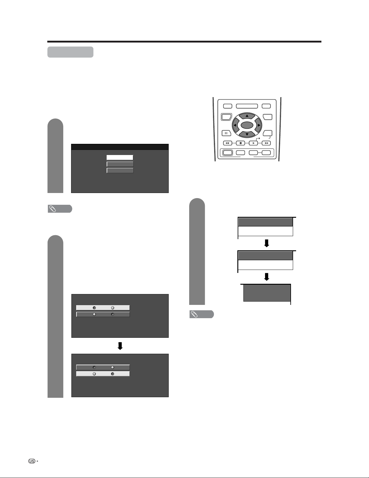
22
Watching TV
Press a/b to select the desired language
listed on the screen, and then press SET/
ENTER.
Press c/d to select “Air” or “Cable” for ANT-
A, then press a/b to move down.
Press c/d to select “Air” or “Cable” for ANT-
B.
Press SET/ENTER to enter the setting.
• This operation makes the System search for
both ANT-A and B.
Initial setup
When you turn on the System for the first time, it will automatically memorize the broadcasting channels where
you live. Perform the following steps before you press TV POWER on the remote control unit.
1. Insert the batteries into the remote control unit. (See page 13.)
2. Connect the antenna cable to the AVC System. (See pages 17 to 19.)
3. Plug in the AC cord to the AC outlet. (See page 20.)
Channel search
Channel auto search makes the System look for all
channels viewable in the set area.
3
1
2
English
Español
Français
ANT-A Air
ANT-B
Cable
Air Cable
CH Search
ANT-A [ ]2Air
CH Search
ANT-B [ ]2Cable
RECEIVER
POWER
TV/SAT/DVD
RETURN
MENU
SET/
ENTER
MENU
FAVORITE CH
DTV/DVD TOP
SOURCE DTV/SAT
DTV/SAT
VCR REC
ABCD
POWER
MENU
GUIDE
INPUT VOL
ⴑ
VOL
ⴐ
INFO
ANT-A Air
ANT-B
Cable
Air Cable
Example
2
ANT-A
Language setting
Select from among 3 languages: English, French and
Spanish.
Antenna setting
NOTE
• Make sure what kind of connection is made with your
System when selecting “Air” or “Cable” for both ANT-A
and B.
Example
NOTE
• Make sure what kind of connection is made with your
System when selecting “Air” or “Cable” for both ANT-A
and B.
• If no channel is found, make sure what kind of connection
is made with your System and try EZ setup again (see
page 27).
• The illustrations and on-screen displays in this operation
manual are for explanation purposes and may vary slightly
from the actual operations.
23
Watching TV
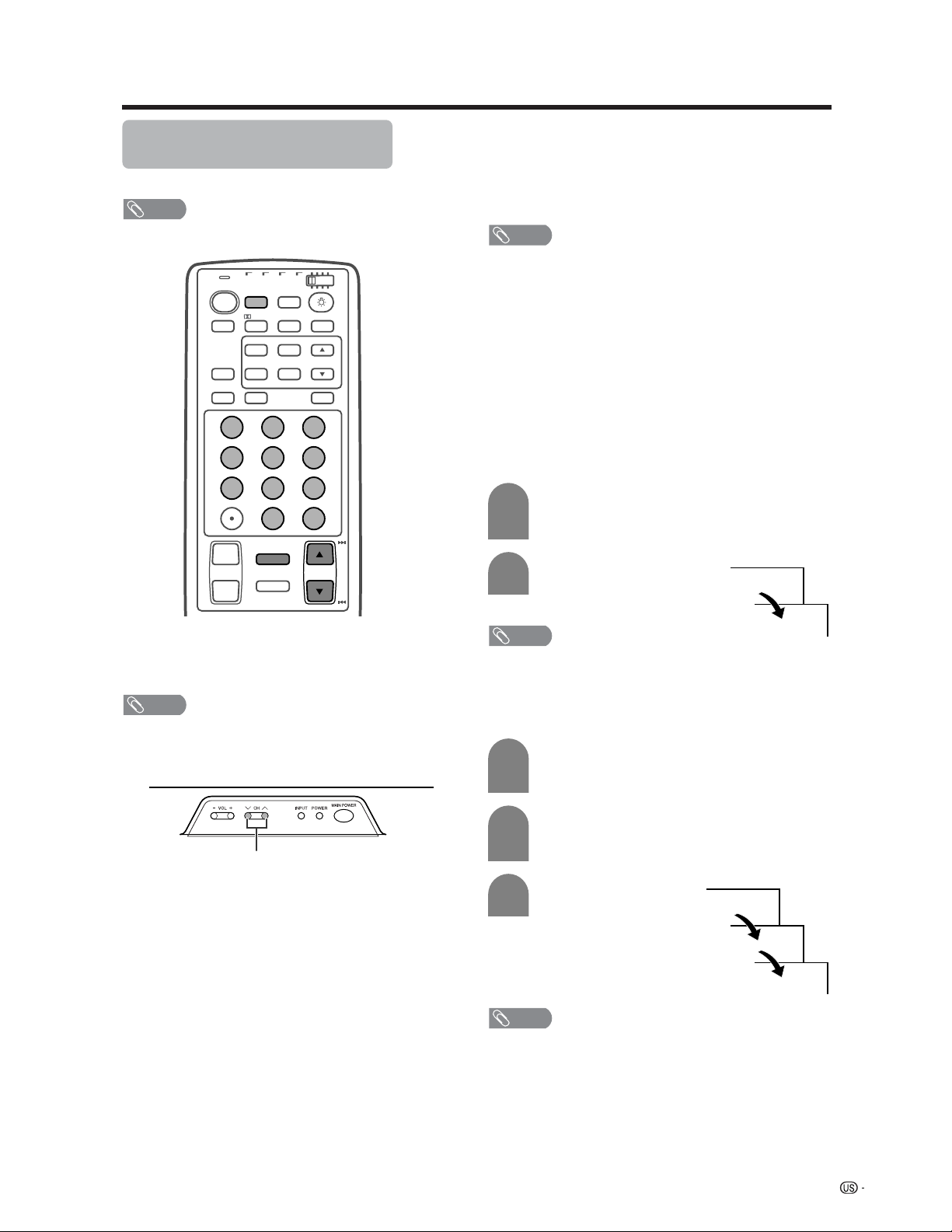
Simple button operations for
changing channels
You can change channels in several ways.
NOTE
• While watching a broadcast, press ANT-A/B to view the
image received from the other tuner.
■ Using CHa/b on the remote control unit
• Press CH
aa
aa
a to increase the channel number.
• Press CH
bb
bb
b to decrease the channel number.
NOTE
• CH s/r on the Display operates the same as CH
aa
aa
a/
bb
bb
b
on the remote control unit.
■ Changing channels with CH a/b on the
remote control unit or CH s/r on the
Display
Air: Press CH a and the channel change in the
order shown below:
2s3s...s68s69s2s3...
Press CH b and the channel change in the order
shown below:
3s2s69s68s...s3s2...
Cable:Press CH a and the channel change in the
order shown below:
1s2s3s...s125s1s2s3...
Press CH b and the channel change in the order
shown below:
3s2s1s125s...s3s2s1s...
■ Using 0 – 9 and 100 on the remote control
unit
Select the channels directly by pressing buttons 0 to
9 and 100.
• The System allows you to select up to 125 channels
(1 to 125). To select a channel, enter a 2 or 3-digit
number.
NOTE
• When selecting a 1-digit channel number, do not fail to
press the 0 button.
To select a 3-digit channel number
(e.g., Channel 115):
Complete the following steps within 3 seconds.
–0
5
Display
CH s/r
a
To select a 1 or 2-digit channel number
(e.g., Channel 5):
Complete the following steps within 3 seconds.
1
1
2
Press the 0 button.
• Complete the step 2 within 3 seconds after the
step 1.
Press the 5 button.
■ Using FLASHBACK on the remote control
unit
Press FLASHBACK to switch the currently tuned
channel to the previously tuned channel.
Press FLASHBACK again to switch back to the
currently tuned channel.
NOTE
• FLASHBACK will not work if no channel has been
changed after the System is turned on.
–
–
–1
11
115
3
2
Press the 100 button.
• Complete the step 2 within 3 seconds after the
step 1.
Press the 1 button.
• Complete the step 3 within 3 seconds after the
step 2.
Press the 5 button.
TV
ANT-A/B
INPUT
TWIN
MODE
AV
POWER
MTS CC
PICTURE
SELECT
SUB TWIN CH
ⴐ
ⴑ
FREEZE
MODE
VOL CH
MUTE
VIEW
SLEEP LEARN
EDIT/
ENT
FLASHBACK
DISPLAY
INPUT
TV VCRCBL
/SAT
/DTV
DVD
/LD
123
456
789
100
0
Virtual
NOTE
• The 100 button is only enabled when selecting channels
in Cable mode.
24
Watching TV
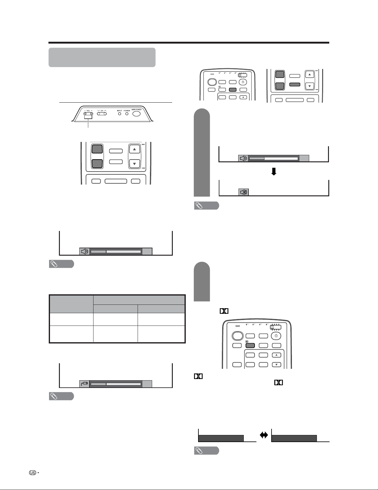
Volume adjustment
Mute
■ Using VOL
kk
kk
k/
ll
ll
l on the remote control unit
• To increase the volume, press VOL
kk
kk
k.
• To decrease the volume, press VOL
ll
ll
l.
Output device
Variable sound
Audio out
VariableFixed
Variable sound
Constant as
specified
Mute
NOTE
• VOL l/kon the Display operates the same as VO L k/l
on the remote control unit.
Audio status
Speaker
MONITOR OUT
Simple button operations for
changing volume/sound
■ Changing the volume
You can change the volume on the Display or on the
remote control unit.
* When “Audio Out” is set to “Variable”, the indicator on the
screen changes as shown below.
NOTE
• See page 57 for details on the audio out function.
■ Using MUTE on the remote control unit
Mutes the current sound output.
Press MUTE.
•“M” has been displayed on the screen for 30
minutes, and the sound is silenced.
NOTE
• Within 30 minutes of pressing MUTE, mute can be
canceled by using one of the methods below.
• Pressing VOL l/k on the Display or VOL k/l, MTS
or MUTE on the remote control unit can also cancel the
mute.
• Mute will be canceled after 30 minutes have passed.
However, the System will not suddenly output a loud
sound as the volume level is set to 0 automatically.
Within 30 minutes, press MUTE again to
cancel the mute.
• Before 30 minutes, the volume level returns to
the previous setting.
• After 30 minutes, increase the volume level by
pressing VOL k.
20
20
ⴐ
ⴑ
VOL CH
MUTE
MENU
DTV/DVD TOP
MENU
FLASHBACK
TV/SAT/DVD
RETURN
MENU
Display
VOL l/k
TV
ANT-A/B
INPUT
TWIN
MODE
AV
POWER
MTS CC
PICTURE
SELECT
TV VCRCBL
/SAT
/DTV
DVD
/LD
Virtual
20
1
2
ⴐ
ⴑ
VOL
MUTE
CH
MENU TV/SAT/DVD
DTV/DVD TOP
RETURN
MENU
MENU
FLASHBACK
Dolby Virtual : Off
Dolby Virtual : On
INPUT
TV
ANT-A/B
TWIN
MODE
AV
POWER
MTS CC
PICTURE
SELECT
SUB TWIN CH
FREEZE
MODE
VIEW
INPUT
TV VCRCBL
/SAT
/DTV
DVD
/LD
Virtual
■ Using Virtual on the remote control unit
Virtual produces Dolby virtual effect from the
speakers. Each time you press
Virtual, the mode
changes between On and Off.
Dolby Virtual sound options
• On: Makes it possible to enjoy natural, realistic
surround sound.
• Off: Outputs the normal sound.
NOTE
• You can have the same settings by choosing “Dolby
Virtual” on the menu items. (See page 38.)
25
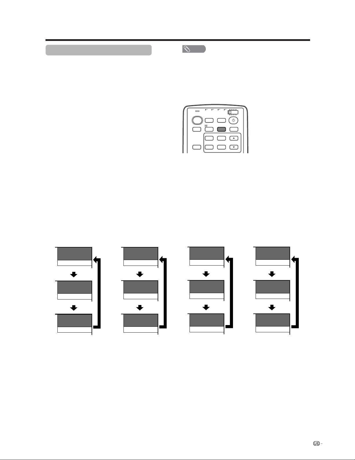
Watching TV
NOTE
• Once “MONO” mode is selected, the sound remains mono
even if the System receives a stereo broadcast. You must
switch the mode back to “STEREO” if you want to hear
stereo sound again.
• Selecting MTS while in the input mode does not change
the type of sound. In this case, sound is determined by
the video source.
Each time you press
MTS, MTS toggles as
shown below.
STEREOkSAP mode MONO mode
MTS
TV
ANT-A/B
INPUT
TWIN
MODE
AV
POWER
CC
PICTURE
SELECT
SUB TWIN CH
FREEZE
MODE
VIEW
INPUT
TV VCRCBL
/SAT
/DTV
DVD
/LD
Virtual
38
ANT-A
ST(SAP)
38
ANT-A
SAP(ST)
38
ANT-A
MONO
38
ANT-A
MONO
38
ANT-A
MONO
38
ANT-A
MONO
Examples: when receiving MTS and SAP
38
ANT-A
STEREO
38
ANT-A
STEREO
38
ANT-A
MONO
38
ANT-A
MAIN
38
ANT-A
SAP
38
ANT-A
MONO
STEREO mode MAINkSAP mode
Setting MTS/SAP stereo mode
The System has a feature that allows reception of
sound other than the main audio for the program. This
feature is called Multi-channel Television Sound (MTS).
The System with MTS can receive mono sound, stereo
sound and Secondary Audio Programs (SAP). The SAP
feature allows a TV station to broadcast other
information, which could be audio in another language
or something completely different like weather
information.
You can enjoy Hi-Fi stereo sound or SAP
broadcasts where available.
• Stereo broadcasts
View programs like live sporting events, shows and
concerts in dynamic stereo sound.
• SAP broadcasts
Receive TV broadcasts in either MAIN or SAP sound.
MAIN sound: The normal program soundtrack (either in
mono or stereo).
SAP sound: Listen to second language, supplementary
commentary and other information. (SAP is mono sound.)
If stereo sound is difficult to hear.
• Obtain a clearer sound by manually switching to fixed
mono-sound mode.
26
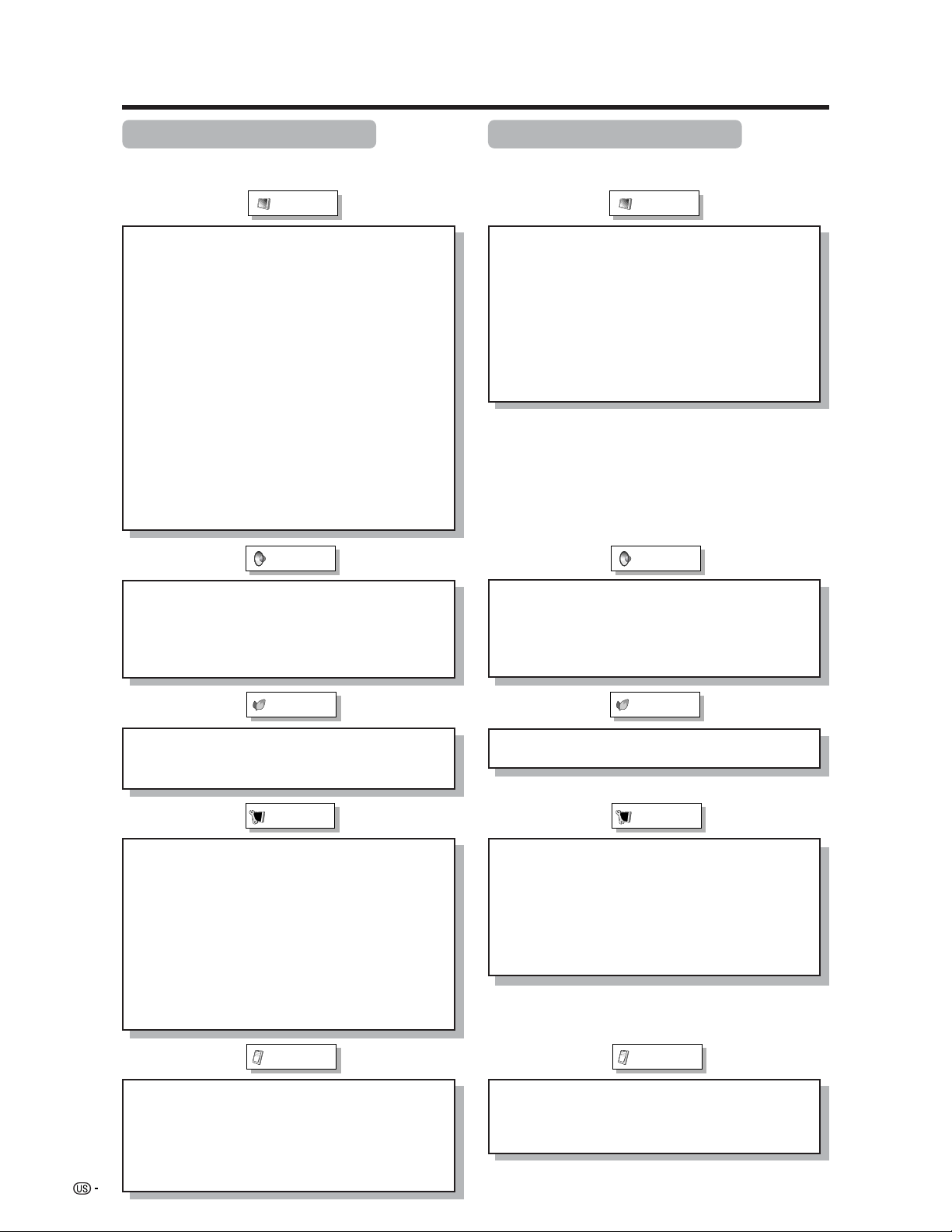
Basic adjustment settings
AV input mode menu items
List of AV menu items to help you with
operations
OPC ................................................ Page 32
Backlight ........................................ Page 33
Contrast ......................................... Page 33
Brightness ..................................... Page 33
Color ............................................... Page 33
Tint ................................................. Page 33
Sharpness ...................................... Page 33
Advanced
C.M.S. ................................... Page 34
Color Temp. ......................... Page 35
Black .................................... Page 35
3D-Y/C .................................. Page 36
Monochrome ....................... Page 36
Film Mode ............................ Page 37
I/P Setting ............................ Page 37
Picture
No Signal Off ................................. Page 39
No Operation Off ........................... Page 39
EZ Setup ........................................ Page 27
CH Setup ................................. Pages 28-30
Speaker .......................................... Page 50
Input Signal ................................... Page 52
Parental CTRL ........................ Pages 61-67
Position .......................................... Page 47
Stretch Mode ................................. Page 53
Picture Flip .................................... Page 54
Language ....................................... Page 31
Treble .............................................. Page 38
Bass ............................................... Page 38
Balance .......................................... Page 38
Dolby Virtual .................................. Page 38
Audio Only ..................................... Page 58
Input Select.................................... Page 52
DNR ................................................ Page 57
Audio Out ....................................... Page 58
Quick Shoot ................................... Page 59
Audio
Power Control
Setup
Option
PC input mode menu items
List of PC menu items to help you with
operations
OPC ................................................ Page 32
Backlight ........................................ Page 33
Contrast ......................................... Page 33
Brightness ..................................... Page 33
Red ................................................. Page 33
Green .............................................. Page 33
Blue ................................................ Page 33
C.M.S. ............................................. Page 34
Picture
Power Management ...................... Page 40
Speaker .......................................... Page 50
Input Signal ................................... Page 57
Auto Sync. ..................................... Page 51
Fine Sync. ...................................... Page 51
Picture Flip .................................... Page 54
Language ....................................... Page 31
Audio
Power Control
Setup
Treble .............................................. Page 38
Bass ............................................... Page 38
Balance .......................................... Page 38
Dolby Virtual .................................. Page 38
Option
Audio Only ..................................... Page 58
Audio Out ....................................... Page 58
Quick Shoot ................................... Page 59
 Loading...