


CD-BA250H/CD-BA2600H
SERVICE MANUAL
No. S4126CDBA250H
MINI COMPONENT SYSTEM
MODEL CD-BA250H
CD-BA250H Mini Component System consisting of
CD-BA250H (main unit) and CP-BA250H (speaker system).
MINI COMPONENT SYSTEM

 MODEL CD-BA2600H
CD-BA2600H Mini Component System consisting of CD-BA2600H (main unit) and CP-BA2600H (speaker system).
•Note for users in U.K.
Recording and playback of any material may require consent which SHARP is unable to give. Please refer particularly to the provisions of Copyright Act 1956, the Dramatic and Musical Performers Protection Act 1956, the Performers Protection Acts 1963 and 1972 and to any subsequent statutory enactments and orders.
•In the interests of user-safety the set should be restored to its original condition and only parts identical to those specified be used.
CONTENTS |
|
|
Page |
SAFETY PRECAUTION FOR SERVICE MANUAL ........................................................................................................... |
2 |
IMPORTANT SERVICE NOTES (CD-BA250H FOR U.K. ONLY) .............................................................................. |
....... 3 |
SPECIFICATIONS ............................................................................................................................................................. |
3 |
NAMES OF PARTS ........................................................................................................................................................... |
4 |
OPERATION MANUAL ...................................................................................................................................................... |
6 |
DISASSEMBLY ................................................................................................................................................................ |
11 |
REMOVING AND REINSTALLING THE MAIN PARTS ................................................................................................... |
14 |
ADJUSTMENT ................................................................................................................................................................. |
15 |
BLOCK DIAGRAM ........................................................................................................................................................... |
19 |
SCHEMATIC DIAGRAM / WIRING SIDE OF P.W.BOARD .............................................................................................. |
22 |
VOLTAGE ........................................................................................................................................................................ |
38 |
NOTES ON SCHEMATIC DIAGRAM .............................................................................................................................. |
39 |
TYPES OF TRANSISTOR AND LED ................................................................................................................................ |
39 |
WAVEFORMS OF CD CIRCUIT ...................................................................................................................................... |
40 |
TROUBLESHOOTING ..................................................................................................................................................... |
41 |
FUNCTION TABLE OF IC ................................................................................................................................................ |
45 |
FL DISPLAY ...................................................................................................................................................................... |
51 |
WIRING OF PRIMARILY SUPPLY LEADS (CD-BA250H FOR U.K. ONLY) .................................................................... |
52 |
REPLACEMENT PARTS LIST/EXPLODED VIEW |
|
PACKING METHOD (CD-BA250H FOR U.K. ONLY) |
|
This document has been published to be used
SHARP CORPORATION– 1 – |
for after sales service only. |
|
|
|
The contents are subject to change without notice. |
CD-BA250H/CD-BA2600H
SAFETY PRECAUTION FOR
SERVICE MANUAL
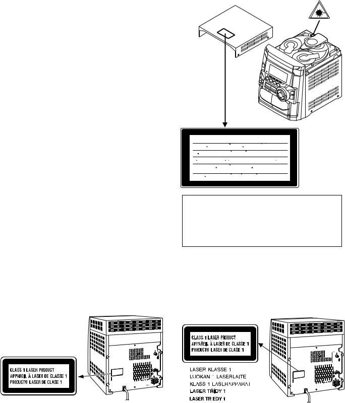
Precaution to be taken when replacing and servicing the Laser Pickup.
The AEL (Accessible Emission Level) of Laser Power Output for this model is specified to be lower than Class 1 Requirements. However, the following precautions must be observed during servicing to protect your eyes against exposure to the Laser beam.
(1)When the cabinet has been removed, the power is turned on without a compact disc, and the Pickup is on a position outer than the lead-in position, the Laser will light for several seconds to detect a disc. Do not look into the Pickup Lens.
(2)The Laser Power Output of the Pickup inside the unit and replacement service parts have already been adjusted prior to shipping.
(3)No adjustment to the Laser Power should be attempted when replacing or servicing the Pickup.
(4)Under no circumstances look directly into the Pickup Lens at any time.
(5)CAUTION - Use of controls or adjustments, or performance of procedures other than those specified herein may result in hazardous radiation exposure.
Laser Diode Properties
Material: GaAIAs
Wavelength: 780 nm
Emission Duration: continuous
Laser Output: max. 0.6 mW
CAUTION-INVISIBLE LASER RADIATION WHEN OPEN. DO NOT STARE INTO
BEAM OR VIEW DIRECTLY WITH OPTICAL INSTRUMENTS.
VARNING-OSYNLIG LASERSTRALNING NAR DENNA DEL AR OPPNAD. STIRRA
EJ IN I STRALEN OCH BETRAKTA EJ STRALEN MED OPTISKA INSTRUMENT.
ADVERSEL-USYNLIG LASERSTRALING VED ABNING. SE IKKE IND I
STRALEN-HELLER IKKE MED OPTISKE INSTRUMENTER.
VARO! AVATTAESSA OLET ALTTIINA NAKYMATON LASERSATEILYLLE.
ALA TUIJOTA SATEESEEN ALAKA KATSO SITA OPTISEN LAITTEEN LAPI.
VARNING-OSYNLIG LASERSTRALNING NAR DENNA DEL AR OPPNAD.
STIRRA EJ IN I STRALEN OCH BETRAKTA EJ STRALEN GENOM OPTISKT
INSTRUMENT.
ADVERSEL-USYNLIG LASERSTRALING NAR DEKSEL APNES. STIRR IKKE
INN I STRALEN ELLER SE DIREKTE MED OPTISKE INSTRUMENTER.
VAROITUS! LAITTEEN KÄYTTÄMINEN MUULLA KUIN TÄSSÄ KÄYTTÖOHJEESSA MAINITULLA TAVALLA SAATTAA ALTISTAA KÄYTTÄJÄN TURVALLISUUSLUOKAN 1 YLITTÄVÄLLE NÄKYMÄTTÖMÄLLE LASERSÄTEILYLLE.
VARNING - OM APPARATEN ANVÄNDS PÅ ANNAT SÄTT ÄN I DENNA BRUKSANVISNING SPECIFICERAS. KAN ANVÄNDAREN UTSÄTTAS FÖR OSYNLIG LASERSTRÅLNING, SOM ÖVERSKRIDER GRÄNSEN FÖR LASERKLASS 1.
(CD-BA250H for U.K. only) |
|
(Except for U.K.) |
|
– 2 –
|
|
CD-BA250H/CD-BA2600H |
||
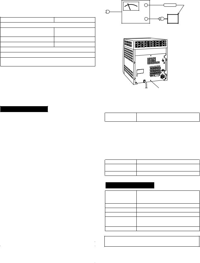
IMPORTANT SERVICE NOTES (CD-BA250H FOR U.K. ONLY) |
||||
Before returning the unit to the customer after completion of a |
WITHSTANDING |
|
||
VOLTAGE TESTER |
|
|||
repair or adjustment it is necessary for the following withstand |
+ |
PROBE |
||
voltage test to be applied to ensure the unit is safe for the |
|
|||
AC |
|
|||
customer to use. |
|
|
||
|
OUT |
|
||
Setting of Withstanding Voltage Tester and set. |
|
|||
- |
|
|||
Set name |
set value |
UNIT |
||
|
||||
Withstanding Voltage Tester |
|
SHORT-CIRCUIT |
CONNECT THE PROBE |
|
Test voltage |
4,240 VPEAK |
AC POWER |
TO GND OF CHASSIS |
|
SUPPLY CORD |
SCREW |
|||
|
3,000 VRMS |
|||
|
|
|
||
Set time |
6 secs |
|
|
|
Set current (Cutoff current) |
4 mA |
|
|
|
Unit |
|
|
|
|
Judgment |
|
|
|
|
OK: The “GOOD” lamp lights.
NG: The “NG” lamp lights and the buzzer sounds.
CHASSIS SCREW
SPECIFICATIONS
CD-BA250H/CD-BA2600H
 General
Power source |
AC 230 V, 50 Hz |
|
|
Power consumption |
Power on: 124 W |
|
Power stand-by: 0.6 W (*) |
|
|
Dimensions |
Width: 270 mm (10-5/8") |
|
Height: 330 mm (13") |
|
Depth: 340 mm (13-3/8") |
|
|
Weight |
6.7 kg (14.7 lbs.) |
|
|
( * ) This power consumption value is obtained when the demonstration mode is cancelled in the power stand-by mode. cancel the demonstration mode.
 Amplifier (CD-BA250H for U.K.)
Output power |
RMS: 150 W (75 W + 75 W) (10 % T.H.D.) |
|
RMS: 104 W (52 W + 52 W) (0.9 % T.H.D.) |
|
|
Output terminals |
Speakers: 6 ohms |
|
Headphones: 16 - 50 ohms (recommended: 32 ohms) |
|
|
Input terminals |
Video/Auxiliary (audio signal): 500 mV/47 kohms |
|
|
 Amplifier (Except for U.K.)
Output power |
PMPO: 480 W |
|
MPO: 240 W (120 W + 120 W) (DIN 45 324) |
|
RMS: 150 W (75 W + 75 W) (DIN 45 324) |
|
RMS: 104 W (52 W + 52 W) (DIN 45 500) |
|
|
Output terminals |
Speakers: 6 ohms |
|
Headphones: 16 - 50 ohms (recommended: 32 ohms) |
|
|
Input terminals |
Video/Auxiliary (audio signal): 500 mV/47 kohms |
|
|
 CD player
Type |
3-disc multi-play compact disc player |
|
|
Signal readout |
Non-contact, 3-beam semiconductor laser pickup |
|
|
D/A converter |
1-bit D/A converter |
|
|
Frequency response |
20 - 20,000 Hz |
|
|
Dynamic range |
90 dB (1 kHz) |
|
|
 Tuner
Tuner
Frequency range |
FM: 87.5 - 108 MHz |
|
AM: 522 - 1,620 kHz |
 Cassette deck (CD-BA250H for U.K.)
Frequency response |
50 - 14,000 Hz (Normal tape) |
|
|
Signal/noise ratio |
55 dB (TAPE 1, playback) |
|
50 dB (TAPE 2, recording/playback) |
|
|
Wow and flutter |
0.3 % (WRMS) |
|
|
 Cassette deck (Except for U.K.)
Frequency response 50 - 14,000 Hz (Normal tape)
Signal/noise ratio 55 dB (TAPE 1, playback)
50 dB (TAPE 2, recording/playback)
Wow and flutter 0.35 % (DIN 45 511)
CP-BA250H/CP-BA2600H
Type |
2-way type speaker system |
|
5 cm (2") Tweeter |
|
13 cm (5-1/4") Woofer |
Maximum input power |
150 W |
Rated input power |
75 W |
Impedance |
6 ohms |
Dimensions |
Width: 220 mm (8-11/16") |
|
Height: 330 mm (13") |
|
Depth: 217 mm (8-9/16") |
Weight |
3.0 kg (6.6 lbs.)/each |
Specifications for this model are subject to change without prior notice.
– 3 –
CD-BA250H/CD-BA2600H
NAMES OF PARTS
CD-BA250H/CD-BA2600H
 Front panel
1.Disc Tray
2.Timer Set Indicator
3.On/Stand-by Button
4.Tape 2 Cassette Compartment
5.Tape 1 Cassette Compartment
6.Equalizer Mode Select Button
7.Volume Up and Down Buttons
8.Extra Bass/Demo Mode Button
9.Disc Tray Open/Close Button 10. Disc Skip Button
11. Tuning and Time Up Button
12. CD or Tape Stop Button
13. CD Button
14. RDS Programme Type/Traffic Information Search Button
15. RDS EON Button
16. RDS ASPM (Auto Station Programme Memory) Button
17. Dimmer Button
18. Clock Button
19. Timer/Sleep Button
20. Headphone Socket
21. RDS Display Mode Selector Button
22. Video/Auxiliary Button
23. Tape (1 2) Button
24. Tuner (Band) Button
25. CD Play or Repeat, Tape Play Button
26. CD Track Up or Fast Forward, Tape 2 Fast Forward, Tuner Preset Up Button
27. Tuning and Time Down Button
28. Memory/Set Button
29. Tape 2 Record Pause Button
30. CD Track Down or Fast Reverse, Tape 2 Rewind, Tuner Preset Down Button
6 |
7 |
8 |
9 |
|
|
|
|
|
|
|
10 |
1
2
3
4
5
11 12 13 |
14 15 16 |
||
|
|
|
21 |
17 |
|
|
22 |
|
|
23 |
|
18 |
|
|
|
|
|
24 |
|
|
|
|
|
19 |
|
|
25 |
20 |
|
|
26 |
|
|
|
|
27 |
28 |
29 |
30 |
 Display
1.RDS Indicator
2.Programme Type Indicator
3.Traffic Announcement Indicator
4.Extra Bass Indicator
5.FM Stereo Mode Indicator
6.Traffic Information Indicator
7.Traffic Programme Indicator
8.CD Play Indicator
9.FM Stereo Receiving Indicator 10. Dynamic PTY Indicator
11. EON Indicator
12. CD Repeat Play Indicator
13. CD Pause Indicator
14. Disc Number Indicators
15. Timer Play Indicator
16. Timer Recording Indicator
17. Tape 2 Record Indicator
18. Memory Indicator
19. Tape Play Indicator
20. Sleep Indicator
21. Spectrum Analyser/Volume Level Indicator
1 |
2 |
3 |
|
14 |
4 |
|
6 |
|
|
|
|
15 |
||
5 |
|
7 |
17 18 19 |
16 |
9 10 11 12 |
13 |
8 |
20 |
|
|
|
|||
|
|
|
21 |
|
21 |
21 |
– 4 –
CD-BA250H/CD-BA2600H
 Rear panel
1.FM 75 Ohms Aerial Sock
2.AM Loop Aerial Socket
3.Video/Auxiliary (Audio Signal) Input Sockets
4.Speaker Terminals
5.AC Power Lead
 Remote control
1.Remote Control Transmitter
2.Disc Number Select Buttons
3.CD Pause Button
4.CD Memory Button
5.CD Track Down or Fast Reverse Button
6.CD Clear Button
7.Tape 1 Play Button
8.Tape 1/Tape 2 Stop Button
9.Equalizer Mode Select Button
10.Tape 2 Record Pause Button
11.CD Button
12.Tuner (Band) Button
13.On/Stand-by Button
14.Extra Bass Button
15.CD Stop Button
16.CD Play or Repeat Button
17.CD Track Up or Fast Forward Button
18.CD Random Button
19.Tuner Preset Up and Down Buttons
20.Tape 2 Play Button
21.Tape 2 Rewind Button
22.Tape 2 Fast Forward Button
23.Video/Auxiliary Button
24.Tape (1  2) Button
25.Volume Up and Down Buttons
CD-BA250H/CD-BA2600H
1
 2
2 

 3
3
4 |
 5
5
1 |
|
|
2 |
15 |
|
|
||
3 |
16 |
|
4 |
17 |
|
5 |
||
18 |
||
6 |
||
19 |
||
7 |
20 |
|
21 |
||
|
||
8 |
22 |
|
23 |
||
9 |
||
10 |
24 |
|
11 |
||
|
||
12 |
25 |
|
13 |
||
|
||
14 |
|
Buttons with " " mark in the illustration can be operated on the remote control only.
Other buttons can be operated both on the main unit and the remote control.
– 5 –
CD-BA250H/CD-BA2600H
CP-BA250H/CP-BA2600H
 Speaker system
1. Tweeter |
1 |
|
2. Woofer |
|
|
3. |
Bass Reflex Duct |
|
4. |
Speaker Wire |
|
|
2 |
3 |
3 |
|
|
|
4 |
OPERATION MANUAL
Setting the Clock
In this example, the clock is set for the 24-hour (0:00) display.
1 Press the ON/STAND-BY button to turn the power on.
2 Press the CLOCK button and within 5 seconds, press the MEMORY/SET button.
3 Press the TUNING/TIME ( or
or  ) button to select 24-hour or 12hour display and then press the MEMORY/SET button.
|
|
|
|
"0:00" |
|
The 24-hour display will appear. |
|
|
|||
|
|||
|
|
(0:00 - 23:59) |
|
"AM 12:00" |
|
The 12-hour display will appear. |
|
|
|||
|
|||
|
|
|
(AM 12:00 - PM 11:59) |
"AM 0:00" |
|
The 12-hour display will appear. |
|
|
|||
|
|||
|
|
|
(AM 0:00 - PM 11:59) |
Note that this can only be set when the unit is first installed or it has been reset. (Refer to step 3 under "If trouble occurs")
4 Press the TUNING/TIME ( or
or  ) button to adjust the hour and then press the MEMORY/SET button.
Press the TUNING/TIME ( or
or  ) button once to advance the time by 1 hour. Holdit down to advance continuously.
When the 12-hour display is selected, "AM" will change automatically to "PM".
5 Press the TUNING/TIME ( or
or  ) button to adjust the minutes and then press the MEMORY/SET button.
Press the TUNING/TIME ( or
or  ) button once to advance the time by 1 minute. Hold it down to change the time in 5-minute intervals.
The hour will not advance even if minutes advance from "59" to "00".
The clock begins counting from "0" seconds. (Seconds are not displayed.) The time display will disappear after a few seconds.
To confirm the time display:
Press the CLOCK button.
The time display will appear for about 5 seconds.
Note:
The "CLOCK" or time will flash at the push of the CLOCK button when the AC power supply is restored after a power failure or unplugging the unit.
Readjust the clock as follows.
To readjust the clock:
Perform "Setting the Clock" from the beginning. If the time display is flashing, step 3 (for selecting the 24-hour or 12-hour display) will be skipped.
To change the 24-hour or 12-hour display:
1Clear all the programmed contents. [Perform to step 3 under "If trouble occurs"
2Perform "Setting the Clock" from the beginning.
– 6 –
CD-BA250H/CD-BA2600H
Troubleshooting Chart
Many potential "problems" can be resolved by the owner without calling a service technician.
If something is wrong with this product, check the following before calling your authorised SHARP dealer or service centre.

 General
Symptom |
Possible cause |
|
|
The clock is not on time. |
Did a power failure occur? Reset the |
|
clock. |
|
|
When a button is pressed, the unit |
Set this unit to the power stand-by mode |
does not respond. |
and then turn it back on. |
|
If the unit still malfunctions, reset it. Refer |
|
to step 3 under "If trouble occurs" |
|
|
No sound is heard. |
Is the volume level set to "0"? |
|
Are the headphones connected? |
|
Are the speaker wires disconnected? |
|
|

 Cassette deck
|
|
Symptom |
Possible cause |
||
|
|
Cannot record. |
Is the erase-prevention tab removed? |
||
|
|
|
|
|
|
|
|
Cannot record tracks with proper |
Is it a normal tape? (You cannot record on |
||
|
|
sound quality. |
ametal or CrO |
|
tape.) |
|
|||||
|
|
Cannot erase completely. |
|
|
|
|
|
|
|
|
|
|
|
Sound skipping. |
Is there any slack? |
||
|
|
|
Is the tape stretched? |
||
|
|
Cannot hear treble. |
Are the capstans, pinch rollers, or heads |
||
|
|
Sound fluctuation. |
dirty? |
||
|
|
|
|
|
|
|
|
|
|
|
|
|
|
Cannot remove the tape. |
If a power failure occurs during playback, |
||
|
|
|
the heads remain engaged with the tape. |
||
|
|
|
Do not open the compartment forcibly. |
||
|
|
|
Wait until electricity resumes. |
||
|
|
|
|
|
|
|
|
Remote control |
|
|
|
|
|
|
|
|
|
|
|
|
|
|
|

 CD player
Symptom |
Possible cause |
Playback does not start. |
Is the disc loaded upside down? |
Playback stops in the middle or is |
Does the disc satisfy the standards? |
not performed properly. |
Is the disc distorted or scratched? |
|
|
|
|
Playback sounds are skipped, or |
Is the unit located near excessive vibra- |
stopped in the middle of a track. |
tions? |
|
Is the disc very dirty? |
|
Has condensation formed inside the unit? |
|
|

 Tuner
Tuner
Symptom |
Possible cause |
Radio makes unusual noise con- |
Is the unit placed near the TV or compu- |
secutively. |
ter? |
|
Is the FM aerial or AM loop aerial placed |
|
properly? Move the AC power lead away |
|
from the aerial if located near. |
Symptom |
Possible cause |
The remote control does not oper- |
Is the AC power lead of the unit plugged |
ate. |
in? |
|
Is the battery polarity respected? |
|
Are the batteries dead? |
|
Is the distance or angle incorrect? |
|
Does the remote control sensor receive |
|
strong light? |

 Condensation
Sudden temperature changes, storage or operation in an extremely humid environment may
cause condensation inside the cabinet (CD pick- 


 up, tape heads, etc.) or on the transmitter on the


 remote control.


 Condensation can cause the unit to malfunction.
If this happens, leave the power on with no disc (or cassette) in the unit until normal playback is possible (about 1 hour). Wipe off any condensa-
tion on the transmitter with a soft cloth before operating the unit.
Troubleshooting Chart
 If trouble occurs
When this product is subjected to strong external interference (mechanical shock, excessive static electricity, abnormal supply voltage due to lightning, etc.) or if it is operated incorrectly, it may malfunction.
If such a problem occurs, do the following:
1Set the unit to the stand-by mode and turn the power on again.
2If the unit is not restored in step 1, unplug and plug in the unit, and then turn the power on.
3If neither step 1 nor 2 restores the unit, do the following:
Press the ON/STAND-BY button to enter the power stand-by mode.
Whilst pressing down the /
/ button and the X-BASS/DEMO button, press the ON/STAND-BY button until "CLEAR AL" appears.
Caution:
This operation will erase all data stored in memory including clock, timer settings, tuner preset, and CD programme.
 Before transporting the unit
1Press the ON/STAND-BY button to turn the power on.
2Press the CD button.
3Press the OPEN/CLOSE button to open the disc tray.
Remove all CDs inserted in the unit.
4Press the OPEN/CLOSE button to close the disc tray.
Make sure that "NO DISC" is displayed.
5Press the ON/STAND-BY button to enter the stand-by mode, and then unplug the AC power lead from the AC socket.
Remote Control

 Test of the remote control
Face the remote control directly to the remote sensor on the unit.
The remote control can be used within the range shown below:
Press the ON/STAND-BY button. Does the power turn on? Now, you can enjoy the music.
Remote sensor
0.2 m - 6 m (8" - 20')
– 7 –
 1
1 Accessories
Remote control × 1 |
AM loop antenna× 1 |
FM antenna × 1
 2
2  Battery installation of remote control
|
Use 2 “AA” size batteries (UM/SUM-3, R6, HP-7 or similar). |
Batteries are not included. |
|||||||||
8 – |
1 Remove the |
2 Insert the batteries |
3 Replace the cover. |
||||||||
– |
battery cover. |
|
as shown. |
|
|||||||
|
|
|
|||||||||
|
|
|
|
|
|
|
|
|
|
|
|
|
|
|
|
|
|
|
|
|
|
|
|
|
|
|
|
|
|
|
|
|
|
|
|
3 System connections |
|
|
-CD |
|
Right speaker |
Left speaker |
|
|
-BA250H/CD |
|
|
FM antenna |
|
BA2600H |
|
|
|
|
|
Red |
Black |
|
AM loop antenna |
|
Left speaker
Right speaker
TV
RCA lead (not supplied)
Wall socket
(AC 230 V, 50 Hz)
To the line
(For U. K.)
output sockets
VCR, DVD, etc.
Wall socket (AC 230 V, 50 Hz) (Except for U. K.)
– 9 –
 4
4 Turn on your system
The first time the unit is plugged, |
1 |
Press the |
the unit will enter the demonstra- |
||
tion mode. You will see words |
|
X-BASS/DEMO button |
|
to cancel the demon- |
|
scroll. |
|
|
|
stration mode. |
|
|
|
Listening to a CD (CDs)
2 Press the ON/ STAND-BY button to turn the power on.
12 cm (5”)
8 cm (3”)
1
2
3
4
5
6
Press the CD button.
Press the  OPEN/CLOSE button to open the disc tray.
Place the CD(s) on the disc tray, label side up.
When loading a third disc, press the DISC SKIP button to turn the disc tray, then place the CD in the open position.
Press the  OPEN/CLOSE button to close the disc tray.
To select the CD you want to listen to first, press one of  1 -
1 -  3 buttons on the remote control.
Press the 
 button to start playback.
Listening to the radio
1
2
FM stereo mode indicator
FM stereo receiving indicator
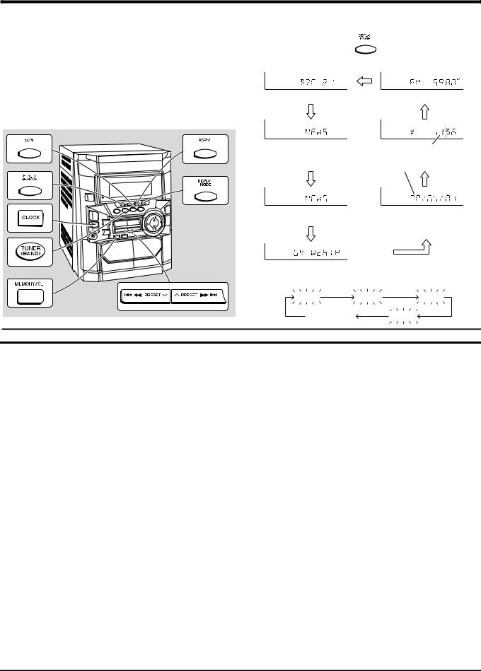
Press the TUNER (BAND) button repeatedly to select the desired frequency band (FM or AM).
Press the TUNING/TIME ( or
or  ) button to tune in to the desired station. When the TUNING/TIME button is pressed for more than 0.5 seconds, scanning will start automatically and the tuner will stop at the first receivable broadcast station.
To receive an FM stereo transmission:
Press the TUNER (BAND) button to display the “ST” indicator.
●“ ” will appear when an FM broadcast is in stereo.
Listening to a cassette tape (TAPE 1 or TAPE 2)
1 |
Open the cassette door by pushing the |
area marked “ PUSH EJECT”. |
Load a cassette into the TAPE 1 or TAPE 2 2 cassette compartment with the side to
be played facing toward you.
3 |
Press the TAPE (1 2) button to select |
|
the cassette you want to listen to. |
||
4 |
Press the |
button to start playback. |
|
|
|
TAPE 1 |
TAPE 2 |
■ If trouble occurs
When this product is subjected to strong external interference (mechanical shock, excessive static electricity, abnormal supply voltage due to lightning, etc.) or if it is operated incorrectly, it may malfunction.
If such a problem occurs, do the following:
1.Set the unit to the stand-by mode and turn the power on again.
2.If the unit is not restored in step 1, unplug and plug in the unit, and then turn the power on.
3.If neither step 1 nor 2 restores the unit, do the following:
Press the ON/STAND-BY button to enter the power
stand-by mode.
Whilst pressing down the 
 button and the X-BASS/ DEMO button, press the ON/STAND-BY button until “CLEAR AL” appears.
■Maintenance
●Dirty heads, capstans or pinch rollers can cause poor sound and tape jams. Clean these parts with a cotton swab moistened with commercial head/pinch roller cleaner or isopropyl alcohol.
●When cleaning the heads, pinch rollers, etc., unplug the unit which contains high voltages.
●After long use, the deck’s heads and capstans may become magnetised, causing poor sound. Demagenetise these parts once every 30 hours of playing/recording time by using a commercial tape head demagnetiser. Read the demagnetiser’s instructions carefully before use.
●Clean the dust or stain on the CD pickup lens using a commercial cleaning disc (brush type).
A Playback head
B Capstan
C Pinch roller
D Erase head
E Recording/Playback head
|
|
A |
B |
C |
TAPE 1 |
|
|
|
|
TAPE 2 |
D |
E B |
C |
|
|
|
|
||
|
|
|
|
|
BA2600H-BA250H/CD-CD
CD-BA250H/CD-BA2600H
Using the Radio Data System (RDS)
RDS is a broadcasting service which a growing number of FM stations provide. These FM stations send additional signals along with their regular programme signals. They send their station names, and information about the type of programme such as sports or music, etc.
When tuned to an RDS station, "RDS" and the station name will be displayed.
"TP" (Traffic Programme) will appear on the display when the received broadcast carries traffic information, and "TA" (Traffic Announcement) will appear whilst a traffic information is on air.
"EON" will appear whilst the EON (Enhanced Other Networks information) data is broadcast.
"PTYI" (Dynamic PTY Indicator) will appear whilst the Dynamic PTY station is received.
"RT" (Radio Text) will appear whilst the unit receives the Radio text data. "CT" (Clock Time) will appear whilst the unit receives the RDS CT data.
You can control the RDS by using the buttons on the main unit only.
 Information provided by RDS
Each time the DISPLAY MODE button is pressed, the display will switch as follows:
Station name (PS) |
Frequency |
Programme type (PTY) |
RDS clock time |
(8 Languages) |
Date (for 3 seconds) |
|
Programme type (PTY) |
Clock-time and date (CT) |
(English fixed) |
|
Radio text (RT)
When you are tuning in to a station other than an RDS station or to an RDS station which sends weak signal, the display will change in the following order:
NO PS |
NO PTY |
NO RT |
FM |
98.80 MHz |
NO CT |
Descriptions of the PTY (Programme Type) codes, TP (Traffic Programme) and TA (Traffic Announcement).
You can search for and receive the following PTY, TP and TA signals.
NEWS |
Short accounts of facts, events and publicly expressed views, reportage |
|
and actuality. |
AFFAIRS |
Topical programme expanding or enlarging upon the news, generally in |
|
different presentation style or concept, including debate, or analysis. |
INFO |
Programmes whose purpose is to impart advice in the widest sense. |
|
|
SPORT |
Programme concerned with any aspect of sport. |
EDUCATE |
Programme intended primarily to educate, of which the formal ele- |
|
ment is fundamental. |
DRAMA |
All radio plays and serials. |
CULTURE |
Programmes concerned with any aspect of national or regional cul- |
|
ture, including language, theatre, etc. |
SCIENCE |
Programmes about the natural sciences and technology. |
|
|
VARIED |
Used for mainly speech-based programmes usually of light-entertain- |
|
ment nature, not covered by other categories. Examples include: |
|
quizzes, panel games, personality interviews. |
|
|
POP M |
Commercial music, which would generally be considered to be of cur- |
|
rent popular appeal, often featuring in current or recent record sales |
|
charts. |
ROCK M |
Contemporary modern music, usually written and performed by |
|
young musicians. |
|
|
EASY M |
Current contemporary music considered to be "easy-listening", as op- |
|
posed to Pop, Rock or Classical, or one of the specialised music |
|
styles, Jazz, Folk or Country. Music in this category is often but not |
|
always, vocal, and usually of short duration. |
LIGHT M |
Classical music for general, rather than specialist appreciation. Ex- |
|
amples of music in this category are instrumental music, and vocal or |
|
choral works. |
CLASSICS |
Performances of major orchestral works, symphonies, chamber mu- |
|
sic, etc., and including Grand Opera. |
|
|
OTHER M |
Musical styles not fitting into any of the other categories. Particularly |
|
used for specialist music of which Rhythm & Blues and Reggae are |
|
examples. |
|
|
WEATHER |
Weather reports and forecasts and meteorological information. |
|
|
FINANCE |
Stock Market reports, commerce, trading, etc. |
|
|
CHILDREN |
For programmes targeted at a young audience, primarily for entertain- |
|
ment and interest, rather than where the objective is to educate. |
|
|
SOCIAL |
Programmes about people and things that influence them individually |
|
or in groups. Includes: sociology, history, geography, psychology and |
|
society. |
RELIGION |
Any aspect of beliefs and faiths, involving a God or Gods, the nature |
|
of existence and ethics. |
PHONE IN |
Involving members of the public expressing their views either by |
|
phone or at a public forum. |
TRAVEL |
Features and programmes concerned with travel to near and far des- |
|
tinations, package tours and travel ideas and opportunities. Not for |
|
use for announcements about problems, delays, or roadworks affect- |
|
ing immediate travel where TP/TA should be used. |
LEISURE |
Programmes concerned with recreational activities in which the listen- |
|
er might participate. Examples include, Gardening, Fishing, Antique |
|
collecting, Cooking, Food & Wine, etc. |
JAZZ |
Polyphonic, syncopated music characterised by improvisation. |
COUNTRY |
Songs which originate from, or continue the musical tradition of the |
|
American Southern States. Characterised by a straightforward melo- |
|
dy and narrative story line. |
NATION M |
Current Popular Music of the Nation or Region in that country's lan- |
|
guage, as opposed to International 'Pop' which is usually US or UK |
|
inspired and in English. |
OLDIES |
Music from the so-called "golden age" of popular music. |
|
|
FOLK M |
Music which has its roots in the musical culture of a particular nation, |
|
usually played on acoustic instruments. The narrative or story may be |
|
based on historical events or people. |
|
|
DOCU- |
Programme concerned with factual matters, presented in an investi- |
MENT |
gative style. |
|
|
TEST |
Broadcast when testing emergency broadcast equipment or receiv- |
|
ers. |
|
|
ALARM ! |
Emergency announcement made under exceptional circumstances to |
|
give warning of events causing danger of a general nature. |
|
|
NONE |
No programme type (receive only). |
|
|
TP |
Broadcasts which carry traffic announcements. |
|
|
TA |
Traffic announcements are being broadcast. |
|
|
Note:
When you select a programme in the EON stand-by mode, the unit will display "TI" instead of "TA".
– 10 –
CD-BA250H/CD-BA2600H
DISASSEMBLY
Caution on Disassembly
Follow the below-mentioned notes when disassembling the unit and reassembling it, to keep it safe and ensure excellent performance:
1.Take cassette tape and compact disc out of the unit.
2.Be sure to remove the power supply plug from the wall outlet before starting to disassemble the unit.
3.Take off nylon bands or wire holders where they need to be removed when disassembling the unit. After servicing the unit, be sure to rearrange the leads where they were before disassembling.
4.Take sufficient care on static electricity of integrated circuits and other circuits when servicing.
CD-BA250H/CD-BA2600H
STEP |
REMOVAL |
|
PROCEDURE |
FIGURE |
|||||
|
|
|
|
|
|
|
|
|
|
1 |
Top Cabinet |
1. |
Screw ...................... |
(A1) x4 |
11-1 |
||||
2 |
Side Panel |
1. |
Screw ...................... |
(B1) x8 |
11-1 |
||||
|
(Left/Right) |
|
|
|
|
|
|
|
|
|
|
|
|
|
|
|
|
|
|
3 |
CD Player Unit/ |
1. |
Turn on the power supply, |
|
|
|
|
11-2 |
|
.. |
|||||||||
|
CD Tray Cover |
|
|
|
|
|
|
|
|
|
|
open the disc tray, take out |
|
|
|
||||
|
|
|
the CD tray cover, and close. |
|
|||||
|
|
|
(Note 1) |
|
|
|
|
|
|
|
|
2. |
Screw ...................... |
(C1) x1 |
|
||||
|
|
3. |
Hook ........................ |
(C2) x3 |
|
||||
|
|
4. |
Hook ........................ |
(C3) x2 |
|
||||
|
|
5. |
Socket ..................... |
(C4) x2 |
|
||||
|
|
|
|
|
|
|
|
|
|
4 |
Rear Panel with |
1. |
Screw .................... |
(D1) x10 |
11-2 |
||||
|
Fan Motor |
2. |
Socket ..................... |
(D2) x1 |
|
||||
5 |
Main PWB |
1. |
Screw ...................... |
(E1) x3 |
11-2,12-2 |
||||
|
|
2. |
Socket ..................... |
(E2) x3 |
|
||||
|
|
3. |
Flat Cable ............... |
(E3) x1 |
|
||||
|
|
4. |
Flat Wire .................. |
(E4) x1 |
|
||||
|
|
|
|
|
|
|
|
|
|
6 |
Front Panel |
1. |
Screw ....................... |
(F1) x2 |
12-2 |
||||
|
|
|
|
|
|
|
|
|
|
7 |
Display PWB |
1. |
Screw .................... |
(G1) x12 |
12-3 |
||||
|
|
2. |
Flat Cable ............... |
(G2) x1 |
|
||||
|
|
|
|
|
|
|
|
|
|
8 |
Tape Mechanism |
1. |
Open the cassette holder |
|
|
12-3 |
|||
.. |
|||||||||
|
|
2. |
......................Screw |
(H1) |
x5 |
|
|
||
9 |
Headphones PWB |
1. |
Screw ....................... |
(J1) x1 |
12-3 |
||||
10 |
Turntable |
1. |
Hook ........................ |
(K1) x2 |
12-4 |
||||
|
|
2. |
Cover ...................... |
(K2) x1 |
|
||||
|
|
|
|
|
|
|
|
|
|
11 |
Disc Tray |
1. |
Turn fully the lock |
lever in the |
11-3 |
||||
|
|
|
arrow direction. |
|
|
|
|
|
|
|
|
2. |
While holding the lock lever,rotate |
12-1 |
|||||
|
|
|
the cam gear until the cam gear |
|
|||||
|
|
|
rib engages with the clamp lever. |
|
|||||
|
|
3. |
Push the slide chassis backward to |
12-5 |
|||||
|
|
|
engage the claw with the groove |
|
|||||
|
|
|
and remove it in the direction |
|
|||||
|
|
|
of the arrow. ............... |
(L1) x6 |
|
||||
|
|
|
|
|
|
|
|
|
|
12 |
CD Servo PWB |
1. |
Screw ...................... |
(M1) x1 |
12-6 |
||||
|
(Note 2) |
2. |
Hook ........................ |
(M2) x2 |
|
||||
|
|
3. |
Socket ..................... |
(M3) x4 |
|
||||
|
|
|
|
|
|
|
|
|
|
13 |
CD Mechanism |
1. |
Hook ........................ |
(N1) x2 |
13-1 |
||||
|
|
2. |
Hook ........................ |
(N2) x3 |
|
||||
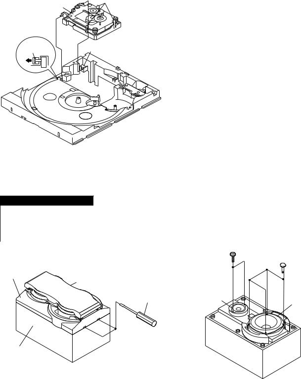
Note 1: How to open the changer manually. (Fig. 11-3)
1.In this state, turn fully the lock lever in the arrow direction through the hole on the loading chassis bottom.
2.While holding the lock lever, rotate the cam gear anticlockwise until the cam gear rib engages with the clamp lever. (Fig. 12-1)
3.After that, push forward the CD slide chassis.
Note 2:
1. After removing the connector for the optical pickup from the connector, wrap the conductive aluminium foil around the front end of the connector so as to protect the optical pickup from electrostatic damage.
CD-BA250H/CD-BA2600H
(A1) x 2
ø3 x 12mm |
Top Cabinet |
|
Side Panel (Right)
(B1) x 2 |
|
|
|
|
ø3 x 10mm |
|
|
|
(A1) x 2 |
|
|
|
|
ø3 x 12mm |
|
|
|
|
Side Panel |
|
|
|
|
(Left) |
(B1) x 4 |
|
|
|
(B1) x 2 |
ø3 x 10mm |
|
|
|
|
|
|
|
ø3 x 10mm |
|
|
Rear |
|
|
|
|
|
|
|
|
|
Panel |
|
|
|
|
|
|
Figure 11-1 |
|
|
CD Servo |
|
CD Tray Cover |
|
|
PWB |
|
|
|
|
|
|
|
|
|
|
(C4) x 2 |
(C2) x 3 |
|
|
|
|
|
|
|
|
|
|
1 |
(C3) x 1 |
|
|
|
|
Pull |
|
|
|
1 |
|
|
|
|
2 |
|
|
|
|
CD Player |
Rear |
|
|
|
Unit |
|
|
|
|
|
Panel |
|
|
|
(C3) x 1 |
(C1) x 1 |
|
|
|
|
ø3 x 10mm |
|
|
|
|
|
|
|
|
(E1) x 1 |
|
|
|
|
ø3 x 10mm |
(D2) x 1 |
|
|
|
Lug Wire |
|
|
|
Main PWB |
(D1) x 2 |
(D1) x 8 |
|
|
ø3 x 10mm |
|
|
|
|
||
|
|
|
|
|
ø3 x 10mm |
|
Figure 11-2 |
||
|
|
|
||
Lock Lever
CD Player Unit
(Bottom View)
Figure 11-3
Note 3:
1.Be careful not to break the claw of the CD mechanism.
2.When fining back the cam gear assembly, let it lock by front movement.
– 11 –

CD-BA250H/CD-BA2600H
(K2) x 1
Clamp Lever
Turntable
CD Player Unit
(Top View)
Cam Gear Rib
Slide
Chassis
(K1) x 2
Figure 12-1
(E2) x 2
(E4) x 1
Headphones (E1) x 2 PWB
ø3 x 10mm
Power PWB
(E3) x 1 |
(E2) x 1 |
Front Panel
Transformer
PWB
2
(F1) x 2 1
ø3 x 8mm
Main PWB
Figure 12-2
 (G2) x 1
|
Front Panel |
|
|
Display PWB |
|
(G1) x 12 |
(M1) x 1 |
|
ø3 x 10mm |
||
ø3 x 8mm |
||
|
||
Tape |
(M3) x 2 |
|
|
||
Mechanism |
|
|
|
(M2) x 2 |
|
(H1) x 5 |
Open |
|
ø3 x 10mm |
|
|
|
Cassette |
|
|
Holder |
(J1) x 1
ø3 x 10mm
Lug Wire |
(M3) x 2 |
Headphones
PWB
Figure 12-3
– 12 –
CD Player Unit
Figure 12-4
(L1) x 3
3
(L1) x 3
Figure 12-5
CD Servo |
Slide |
|
Chassis |
||
PWB |
||
|
Figure 12-6
CD |
(N2) x 3 |
Mechanism |
|
(N1) x 1 |
(N1) x 1 |
Figure 13-1
CP-BA250H/CP-BA2600H
STEP |
REMOVAL |
|
PROCEDURE |
|
FIGURE |
|
|
|
|
|
|
1 |
Front Panel |
1. |
Net ......................... |
(A1) x1 |
13-2 |
|
|
|
|
|
|
2 |
Woofer |
1. |
Screw .................... |
(B1) x4 |
13-3 |
|
|
|
|
|
|
3 |
Tweeter |
1. |
Screw .................... |
(C1) x2 |
13-3 |
|
|
|
|
|
|
Front Panel
Screwdriver
|
Driver should |
|
be pried away |
Speaker Box |
from Speaker Box. |
|
Figure 13-2
CD-BA250H/CD-BA2600H
(C1) x 2
ø3 x 10mm
 (B1) x 4
  ø4 x 12mm
Tweeter
Woofer
Figure 13-3
– 13 –
CD-BA250H/CD-BA2600H
REMOVING AND REINSTALLING THE MAIN PARTS
TAPE MECHANISM SECTION
Perform steps 1 to 6 and 8 of the disassembly method to remove the tape mechanism.
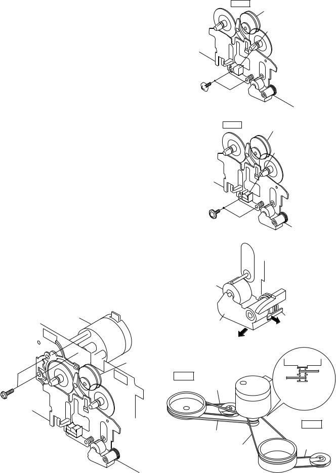
How to remove the record/playback and erase heads (TAPE 2) (See Fig. 14-1)
1.When you remove the screws (A1) x 2 pcs., the recording/ playback head and three-dimensional head of the erasing head can be removed.
How to remove the playback head (TAPE 1) (See Fig. 14-2)
1.When you remove the screws (B1) x 2 pcs., the playback head.
How to remove the pinch roller (TAPE 1/2) (See Fig. 14-3)
1.Carefully bend the pinch roller pawl in the direction of the arrow <A>, and remove the pinch roller (C1) x 1 pc., in the direction of the arrow <B>.
Note:
When installing the pinch roller, pay attention to the spring mounting position.
How to remove the belt (TAPE 2) (See Fig. 14-4)
1.Remove the main belt (D1) x 1 pc., from the motor side.
2.Remove the FF/REW belt (D2) x 1 pc.
TAPE 2
Clutch Ass'y
Record/Playback
Head
Erase Head 

 (A1) x 2 Ø2 x 9mm
Figure 14-1
TAPE 1
Clutch Ass'y
Playback
Head
(B1) x 2 Ø2 x 9mm
Figure 14-2
How to remove the belt (TAPE 1) (See Fig. 14-4)
1.Remove the main belt (E1) x 1 pc., from the motor side.
2.Remove the FF/REW belt (E2) x 1 pc.
How to remove the motor (See Fig. 14-5)
1. Remove the screws (F1) x 2 pcs., to remove the motor.
Motor |
|
|
Pinch |
|
|
Pinch Roller |
Roller |
|
|
|
<A> Pawl |
|
||
|
(C1) x 1 |
|
|
|
|
Pull |
|
|
|
|
|
|
|
|
|
|
<B> |
|
|
|
|
Figure 14-3 |
|
|
Clutch Ass'y |
|
|
Motor |
|
|
|
|
||
TAPE 2 |
FF/REW |
Motor |
|
TAPE 1 |
|
|
|||
|
Belt |
|
TAPE 2 |
Main Belt |
|
(D2) x 1 |
|
(E1) x 1 |
|
|
|
Main Belt |
||
|
|
|
|
|
|
|
|
(D1) x 1 |
|
(F1) x 2 |
|
|
|
|
Ø2.6 x 5 mm |
|
|
|
|
|
|
|
|
TAPE 1 |
|
Main Belt |
|
|
FF/REW |
|
(D1) x 1 |
|
|
Belt |
|
|
Main Belt |
|
(E2) x 1 |
|
|
|
|
|
|
|
(E1) x 1 |
|
|
Figure 14-5 |
|
Figure 14-4 |
|
|
– 14 –
CD MECHANISM SECTION
Perform steps 1, 2, 3, 10, 11, 12 and 13 of the disassembly method to remove the CD mechanism.
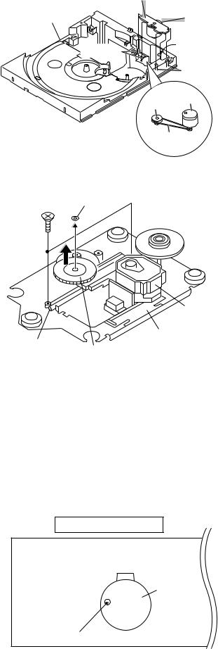
How to remove the loading motor (See Fig. 15-1)
1.Bend the hooks (A1) x 5 pcs., to remove the loading motor.
2.Remove the drive belt (A2) x 1pc.
CD-BA250H/CD-BA2600H
Loading
Motor PWB
Slide |
Loading |
|
Chassis |
||
Motor |
||
|
||
|
(A1) x 1 |
|
|
(A1) x 2 |
|
|
(A1) x 2 |
|
|
Loading |
|
|
Pulley Motor |
|
|
Drive Belt |
|
|
(A2) x 1 |
|
|
Figure 15-1 |
How to remove the pickup (See Fig. 15-2)
1.Remove the stop washer (B1) x 1 pc., to remove the gear (B2) x 1 pc.
2.Remove the screws (B3) x 2 pcs., to remove the shaft (B4).
3.Remove the pickup.
Note
After removing the connector for the optical pickup from the connector wrap the conductive aluminium foil around the front end of connector so as to protect the optical pickup from electrostatic damage.
(B3) x 2 |
Stop Washer |
|
|
ø2.6 x 6mm (B1) x 1 |
|
Pickup
Shaft |
CD Mechanism |
|
Gear |
||
(B4) x 1 |
||
(B2) x 1 |
||
|
||
|
Figure 15-2 |
ADJUSTMENT
MECHANISM SECTION
• Driving Force Check
Torque Meter |
Specified Value |
|
|
Play: TW-2111 |
Tape 1: Over 80 g |
|
Tape 2: Over 80 g |
|
|
• Torque Check
Torque Meter |
Specified Value |
|
|
|
|
|
Tape 1 |
Tape 2 |
|
|
|
Play: TW-2111 |
30 to 80 g.cm |
30 to 80 g.cm |
|
|
|
Fast forward: TW-2231 |
— |
70 to 180 g.cm |
|
|
|
Rewind: TW-2231 |
— |
70 to 180 g.cm |
|
|
|
• Tape Speed
|
Test Tape |
Adjusting |
Specified |
Instrument |
|
|
Point |
Value |
Connection |
|
|
|
|
|
Normal |
MTT-111 |
Variable |
3,000 ± 30 Hz |
Speaker |
speed |
|
Resistor in |
|
Terminal |
|
|
motor. |
|
(Load |
|
|
|
|
resistance: |
|
|
|
|
6 ohms) |
|
|
|
|
|
TAPE MECHANISM
Tape
Motor
Variable Resistor in motor
Figure 15-3
– 15 –
CD-BA250H/CD-BA2600H
TUNER SECTION
fL: Low-range frequency fH: High-range frequency
• AM IF/RF
Signal generator: 400 Hz, 30%, AM modulated
Test Stage |
Frequency |
Frequency |
Setting/ |
Instrument |
|
|
Display |
Adjusting |
Connection |
|
|
|
Parts |
|
|
|
|
|
|
AM IF |
450 kHz |
1,620 kHz |
T351 |
*1 |
|
|
|
|
|
AM Band |
— |
522 kHz |
(fL): T306 |
*2 |
Coverage |
|
|
1.1 ± 0.1 V |
|
AM Tracking |
990 kHz |
990 kHz |
(fL): T303 |
*1 |
|
|
|
|
|
• FM
Notes:
1:Description of the "FM IF Adjustment" is not carried on this Manual. It is because the IF coil in the FM front end section has been best adjusted in the factory so that its further adjustment is not needed at the field. When replacing the FM front end assembly, no adjustment is needed either.
2:The parts in the FM front end section are prepared in a complete unit, so you can't obtain each part individually.
*1. Input: Antenna |
Output: TP302 |
|
|
|
|
MAIN PWB |
|
||
*2. Input: Antenna |
Output: TP301 |
|
|
|
|
|
|
||
|
SO302 |
CNP302 |
||
|
FM |
AM LOOP |
||
|
ANTENNA |
ANTENNA |
||
FE301 |
T303 AM |
|
TRACKING fL |
R336 |
AM BAND |
COVERAGE fL |
|
TP301 |
T306 |
|
T351
AM IF
TP302
 R357
R357
Figure 16-1 ADJUSTMENT POINTS
CD SECTION
•Adjustment
Since this CD system incorporates the following automatic adjustment functions, readjustment is not needed when replacing the pickup. Therefore, different PWBs and pickups can be combined freely.
Each time a disc is changed, these adjustments are performed automatically. Therefore, playback of each disc can be performed under optimum conditions.
Items adjusted automatically
(1)Offset adjustment (The offset voltage between the head amplifier output and the VREF reference voltage is compensated inside the IC.)
*Focus offset adjustment
*Tracking offset adjustment
(2)Tracking balance adjustment (waveform drawing Fig.16-2 EFBL)
(3)Gain adjustment (The gain is compensated inside the IC so that the loop gain at the gain crossover frequency will be 0 dB.)
*Focus gain adjustment
*Tracking gain adjustment
CD ERROR CODE DESCRIPTION
Error |
State Code |
|
|
|
|
|
|
|
[Servo System Error] |
|
|
0001 |
Cannot detect Pickup-in SW |
|
|
0002 |
DSP access error |
|
|
|
|
|
|
|
[Error during close operation] |
|
|
0101 |
Open/Close SW not functioning (Low → |
High) |
|
0103 |
Open/Close SW not functioning (High → |
Low) |
|
|
[Error during open operation] |
|
|
0201 |
Open/Close SW not functioning (Low → |
High) |
|
0203 |
Open/Close SW not functioning (High → |
Low) |
|
|
[Error during skip operation] |
|
|
0302 |
Pickup-in SW is not detected |
|
|
0306 |
During Disc 1 search, Open/Close SW or Clamp SW |
||
|
or Disc SW do not change to low. |
|
|
0307 |
Clamp SW not function (Low → |
High) |
|
0308 |
Clamp SW not function (High → |
Low) |
|
|
Stopped |
|
T |
|
|
|
|
|
1999/04/05 |
20:26:47 |
|
|
|
|
|
|
|
|
|||
|
CH1=500 mV |
CH2=200 mV |
CH3=1 V |
|
|
500 ms/div |
||||
|
DC |
10:1 |
|
DC |
10:1 |
DC 10:1 |
|
|
(500 ms/div) |
|
|
|
|
|
|
|
|
|
|
NORM:20 kS/s |
|
T |
FDO |
|
|
|
|
|
|
|
|
|
|
|
|
|
|
|
|
|
|
|
|
1 |
|
|
|
|
|
|
|
|
|
|
3 |
TE |
|
|
|
|
|
|
|
|
|
|
|
|
|
|
|
|
|
|
|
|
|
EFBL |
|
|
|
|
|
|
|
|
|
2 |
|
|
|
|
|
|
|
|
|
|
|
|
|
|
|
|
|
|
|
|
CH2 |
|
|
|
|
|
|
|
|
|
|
v/DIV |
|
|
|
|
|
|
|
|
|
|
200 mV |
|
=Filter= |
|
|
=Offset= |
=Record Length= |
|
=Trigger= |
|||
Smoothing : ON |
CH1 : |
0.000 V |
Main : |
100 K |
Mode : SINGLE |
|||||
BW |
: FULL |
|
CH2 : |
0.000 V |
Zoom : |
2 k |
Type |
: EDGE CH1 |
||
|
|
|
CH3 : |
0.00 V |
|
|
Delay : |
0.0 ns |
||
|
|
|
CH4 : |
0.00 V |
|
|
Hold off : |
0.2 s |
||
|
|
|
|
|
Figure 16-2 |
|
|
|
||
– 16 –
CD-BA250H/CD-BA2600H
TEST MODE
• Setting the test mode
Any one of test mode can be set by pressing several keys as follows. <X-BASS> + <CD> + <POWER> TEST:CD operation test.
Function:-CD test mode. -Enter test mode.
C 
 D
D 


 T
T 
 E
E 
 S
S 
 T
T 

IL isn't done.
OPEN/CLOSE operation is using manual.
<< >>, <<
 >> buttons make pick's slide possible.
<<PLAY>> key input.
<<MEMORY>> key input.
Adjustment result automatically will display as below for each 2 sec :
a)"FOFF_XX"
b)"TOFF_XX"
c)"TBAL_XX"
d)"TGAN_XX"
f)"FGAN_XX"
g)"RFLS_XX"
Do TOC IL. Do normal play. When these following key is input into PLAY key, track number can be appoint directly.
<< 1>> key: Track 4 |
|
<< |
2>> key: Track 9 |
<< |
3>> key: Track 15 |
explanation: |
|
|
a) |
Focus off set. |
="FOFF_XX" |
b) |
Tracking off set. |
="TOFF_XX" |
c) |
Tracking balance. |
="TBAL_XX" |
d) |
Tracking gain. |
="TGAN_XX" |
f) |
Focus Gain. |
="FGAN_XX" |
g) |
RF level shift. |
="RFLS_XX" |
VOL — Last memory.
BAL — CENTER
P.GEQ — FLAT
X-BASS — OFF
<<STOP>> key input.
STOP
XX: Hex value.
To cancel : Power OFF
<<MEMORY>> key input.
Laser ON.
<<MEMORY>> key input.
Tracking OFF play at that specific point.
<<MEMORY>> key input.
Tracking ON play from that specific point.
Adjustment result automatically will display as below.
for each 2 sec :
a)"FOFF_XX"
b)"TOFF_XX"
c)"TBAL_XX"
d)"TGAN_XX"
f)"FGAN_XX"
g)"RFLS_XX"
<<STOP>> key input.
STOP
Sliding the PICKUP with << >>, <<
 >> button
must only be in STOP mode.
– 17 –
CD-BA250H/CD-BA2600H
Standard Specification of Stereo System Error Message Display Contents
|
Error Contents |
DISPLAY |
Notes |
|
|
|
|
Output while Device Protection Operation. |
'PROTECT' |
00: While in Protect Circuit Operate. |
|
|
|
|
01: Over Current Detection. |
|
|
|
02: DC Detection. |
|
|
|
03: |
|
|
|
|
TAPE |
Mechanism Error. |
'ER-TA**' |
00: Tape Mechanism Error. |
|
|
|
01: Initial Error. |
|
|
|
02: |
|
|
|
03: |
|
|
|
|
CD/VCD |
Pickup Mechanism Error. |
'ER-CD**' |
00: Pickup Mechanism Error. |
|
|
|
01: PU-IN SW Detection NG. |
|
|
|
02: |
|
|
|
03: |
|
|
|
04: |
|
|
|
|
|
CD Changer Mechanism Error. |
'ER-CD**' |
10: Changer Error. |
|
|
|
11: Initial Error. |
|
|
|
12: |
|
|
|
13: |
|
|
|
|
|
Tray Error. |
'ET-CD**' |
20: Tray Error. |
|
|
|
21: |
|
|
|
22: |
|
|
|
23: |
|
|
|
|
|
Focus Not Match. |
'NO DISC' |
|
|
|
|
|
|
IL Time Over. |
'NOT READ' |
|
|
|
|
|
TUN |
PLL Unlock. |
'ER-TU**' |
00: TUN Error. |
|
|
|
01: PLL Unlock. |
|
|
|
02: |
|
|
|
03: |
|
|
|
|
– 18 –
 Loading...