


MINI COMPONENT SYSTEM MINI-CHAÎNE
SISTEMA MINI
MODEL MODELO MODÈLE 
CD-M4000W
SPEAKER SYSTEM ENCEINTES ACOUSTIQUES SISTEMA DE ALTAVOCES
MODEL MODELO
MODÈLE
CP-M4000
OPERATION MANUAL MANUAL DE MANEJO MODE D’EMPLOI 
ENGLISH 
 Please refer to pages E-1 to E-32.
FRANÇAIS 
 Se reporter aux pages F-1 à F-32.
ESPAÑOL |
Consulte las páginas S-1 a S-32. |
|
|
|
|
|
|
|
|
|
|
|
|
|
SHARP CORPORATION
Instruction |
Special Notes - |
Important |
- Introduction / |
|
|
ENGLISH
Introduction
Thank you for purchasing this SHARP product. To obtain the best performance from this product, please read this manual carefully. It will guide you in operating your SHARP product.
Special Notes
CAUTION
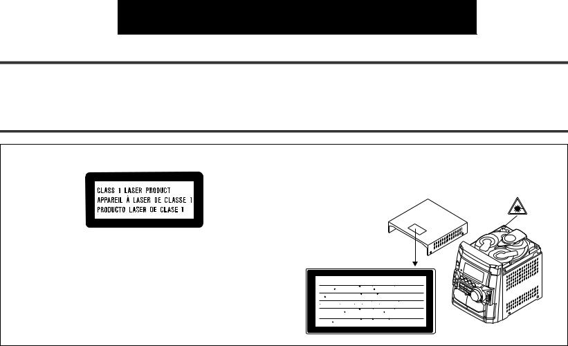
zThis Mini Component System is classified as a CLASS 1 LASER product.
zThe CLASS 1 LASER PRODUCT label is located on the rear cover.
zUse of controls, adjustments or performance of procedures other than those specified herein may result in hazardous radiation exposure.
As the laser beam used in this compact disc player is harmful to the eyes, do not attempt to disassemble the cabinet. Refer servicing to qualified personnel only.
Laser Diode Properties Material: GaAIAs Wavelength: 780 nm Emission Duration: continuous Laser Output: max. 0.6 mW
CAUTION-INVISIBLE LASER RADIATION WHEN OPEN. DO NOT STARE INTO BEAM OR VIEW DIRECTLY WITH OPTICAL INSTRUMENTS.
VARNING-OSYNLIG LASERSTRALNING NAR DENNA DEL AR OPPNAD. STIRRA EJ IN I STRALEN OCH BETRAKTA EJ STRALEN MED OPTISKA INSTRUMENT.
ADVERSEL-USYNLIG LASERSTRALING VED ABNING. SE IKKE IND I
STRALEN-HELLER IKKE MED OPTISKE INSTRUMENTER.
VARO! AVATTAESSA OLET ALTTIINA NAKYMATON LASERSATEILYLLE.
ALA TUIJOTA SATEESEEN ALAKA KATSO SITA OPTISEN LAITTEEN LAPI.
VARNING-OSYNLIG LASERSTRALNING NAR DENNA DEL AR OPPNAD.
STIRRA EJ IN I STRALEN OCH BETRAKTA EJ STRALEN GENOM OPTISKT
INSTRUMENT.
ADVERSEL-USYNLIG LASERSTRALING NAR DEKSEL APNES. STIRR IKKE
INN I STRALEN ELLER SE DIREKTE MED OPTISKE INSTRUMENTER.
zWhen the ON/STAND-BY button is set at STAND-BY position, mains voltage is still present inside the unit. When the ON/STAND-BY button is set at STAND-BY position, the unit may be brought into operation by the timer mode or remote control.
zAudio-visual material may consist of copyrighted works which must not be recorded without the authority of the owner of the copyright. Please refer to the relevant laws in your country.
Warning:
This unit contains no user serviceable parts. Never remove covers unless qualified to do so. This unit contains dangerous voltages, always remove mains plug from the socket before any service operation and when not in use for a long period.
Warning:
To prevent fire or shock hazard, do not expose this appliance to dripping or splashing. No objects filled with liquids, such as vases, shall be placed on the apparatus.
E-1 |
ENGLISH |
|
|
|
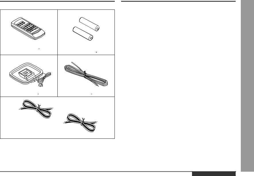
Accessories
Please confirm that the following accessories are included.
Remote control 1 |
"AA" size battery (UM/SUM-3, R6, |
|
HP-7 or similar) 2 |
AM loop aerial 1 |
FM aerial 1 |
Speaker wire  2
2
Note:
Only the above accessories are included.
Contents
Page
Ñ General Information
Precautions . . . . . . . . . . . . . . . . . . . . . . . . . . . . . . . . . . . . . . . . . . . . . . . . . . . . . . . 3
Controls and Indicators . . . . . . . . . . . . . . . . . . . . . . . . . . . . . . . . . . . . . . . . . . 4 - 6
Ñ Preparation for Use
System Connections . . . . . . . . . . . . . . . . . . . . . . . . . . . . . . . . . . . . . . . . . . . . 7 - 10 General Control . . . . . . . . . . . . . . . . . . . . . . . . . . . . . . . . . . . . . . . . . . . . . . . . . . . 10 Remote Control . . . . . . . . . . . . . . . . . . . . . . . . . . . . . . . . . . . . . . . . . . . . . . . . . . . 11
Ñ Basic Operation
Sound Control . . . . . . . . . . . . . . . . . . . . . . . . . . . . . . . . . . . . . . . . . . . . . . . . . . . . 12
Setting the Clock . . . . . . . . . . . . . . . . . . . . . . . . . . . . . . . . . . . . . . . . . . . . . . . . . . 13
Ñ CD Playback
Listening to a CD (CDs) . . . . . . . . . . . . . . . . . . . . . . . . . . . . . . . . . . . . . . . . . 14 - 16 Repeat or Random Play . . . . . . . . . . . . . . . . . . . . . . . . . . . . . . . . . . . . . . . . . . . . 16 Programmed Play . . . . . . . . . . . . . . . . . . . . . . . . . . . . . . . . . . . . . . . . . . . . . . . . . 17
Ñ Radio
Listening to the Radio . . . . . . . . . . . . . . . . . . . . . . . . . . . . . . . . . . . . . . . . . . . . . . 18 Listening to the Memorised Station . . . . . . . . . . . . . . . . . . . . . . . . . . . . . . . . . . . 19
Ñ Tape Playback
Listening to a Cassette Tape (TAPE 1) . . . . . . . . . . . . . . . . . . . . . . . . . . . . . . . . . 20 Listening to a Cassette Tape (TAPE 2) . . . . . . . . . . . . . . . . . . . . . . . . . . . . . . . . . 21
Ñ Karaoke
Playing Karaoke . . . . . . . . . . . . . . . . . . . . . . . . . . . . . . . . . . . . . . . . . . . . . . . . 22, 23
Ñ Tape Recording
Recording from the Radio . . . . . . . . . . . . . . . . . . . . . . . . . . . . . . . . . . . . . . . . . . . 24 Recording from a CD (CDs) . . . . . . . . . . . . . . . . . . . . . . . . . . . . . . . . . . . . . . . . . 25 Dubbing from Tape to Tape . . . . . . . . . . . . . . . . . . . . . . . . . . . . . . . . . . . . . . . . . . 26
Ñ Advanced Features
Timer and Sleep Operation . . . . . . . . . . . . . . . . . . . . . . . . . . . . . . . . . . . . . . . 27, 28
Enhancing Your System . . . . . . . . . . . . . . . . . . . . . . . . . . . . . . . . . . . . . . . . . . . . 29
Ñ References
Troubleshooting Chart . . . . . . . . . . . . . . . . . . . . . . . . . . . . . . . . . . . . . . . . . . 30, 31
Maintenance . . . . . . . . . . . . . . . . . . . . . . . . . . . . . . . . . . . . . . . . . . . . . . . . . . . . . . 31
Specifications . . . . . . . . . . . . . . . . . . . . . . . . . . . . . . . . . . . . . . . . . . . . . . . . . . . . 32
ENGLISH
CD-M4000W
General Information - Accessories / Contents -
E-2
General Information - Precautions -
Precautions
Ñ General
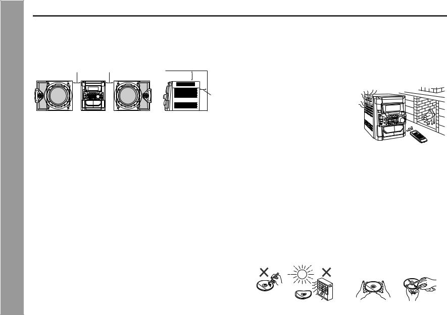
zPlease ensure that the equipment is positioned in a well ventilated area and ensure that there is at least 10 cm (4") of free space along the sides, top and back of the equipment.
10 cm (4") |
10 cm (4") |
10 cm (4")
10 cm (4")
zUse the unit on a firm, level surface free from vibration.
zKeep the unit away from direct sunlight, strong magnetic fields, excessive dust, humidity and electronic/electrical equipment (home computers, facsimiles, etc.) which generates electrical noise.
zDo not place anything on top of the unit.
zDo not expose the unit to moisture, to temperatures higher than 60°C (140°F) or to extremely low temperatures.
zIf your system does not work properly, disconnect the AC power lead from the wall socket. Plug the AC power lead back in, and then turn on your system.
zIn case of an electrical storm, unplug the unit for safety.
zHold the AC power plug by the head when removing it from the wall socket, as pulling the lead can damage internal wires.
zDo not remove the outer cover, as this may result in electric shock. Refer internal service to your local SHARP service facility.
zThe ventilation should not be impeded by covering the ventilation openings with items, such as newspapers, tablecloths, curtains, etc.
zNo naked flame sources, such as lighted candles, should be placed on the apparatus.
zAttention should be drawn to the environmental aspects of battery disposal.
zThis unit should only be used within the range of 5°C - 35°C (41°F - 95°F).
Warning:
The voltage used must be the same as that specified on this unit. Using this product with a higher voltage other than that which is specified is dangerous and may result in a fire or other type of accident causing damage. SHARP will not be held responsible for any damage resulting from use of this unit with a voltage other than that which is specified.
Ñ Volume control
The sound level at a given volume setting depends on speaker efficiency, location, and various other factors. It is advisable to avoid exposure to high volume levels, which occurs whilst turning the unit on with the volume control setting up high, or whilst continually listening at high volumes.
Ñ Condensation
Sudden temperature changes, storage or operation in an extremely humid environment may cause condensation inside the cabinet (CD pickup, tape heads, etc.) or on the transmitter on the remote control.
Condensation can cause the unit to malfunction. If this happens, leave the power on with no disc (or cassette) in the unit until normal playback is possible (about 1 hour). Wipe off any condensation on the transmitter with a soft cloth before operating the unit.
Ñ Care of compact discs
Compact discs are fairly resistant to damage, however mistracking can occur due to an accumulation of dirt on the disc surface. Follow the guidelines below for maximum enjoyment from your CD collection and player.
zDo not write on either side of the disc, particularly the non-label side from which signals are read. Do not mark this surface.
zKeep your discs away from direct sunlight, heat, and excessive moisture.
zAlways hold the CDs by the edges. Fingerprints, dirt, or water on the CDs can cause noise or mistracking. If a CD is dirty or does not play properly, clean it with a soft, dry cloth, wiping straight out from the centre, along the radius.
NO |
|
|
YES |
|
|
Correct |
|
|
|
|
|
|
|
|
|
|
|
|
|
E-3 |
ENGLISH |
|
|
|
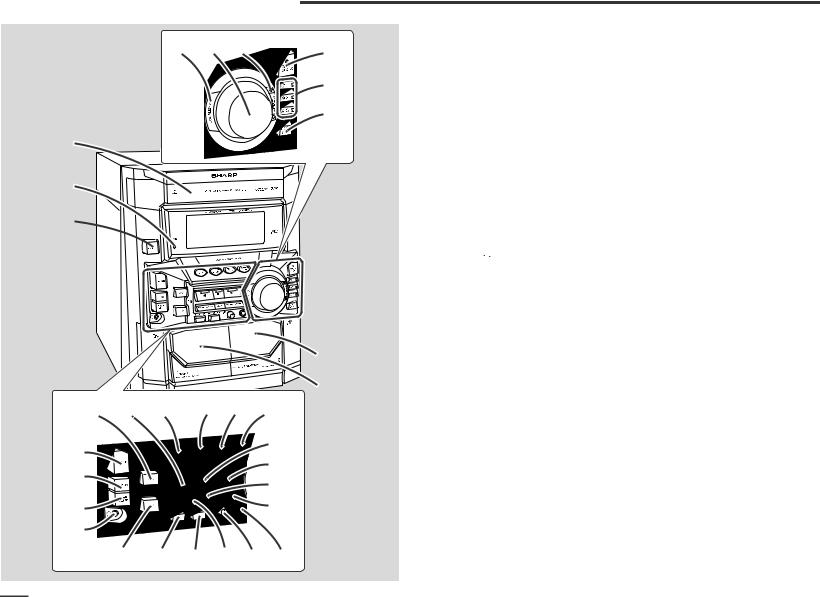
Controls and Indicators
6 |
7 |
8 |
9 |
|
|
|
10
11
1
2
3
4
5
12 |
13 |
14 |
15 16 |
17 |
18 |
|
|
|
22 |
|
|
|
23 |
|
19 |
|
|
|
|
|
|
|
24 |
|
|
|
|
|
|
20 |
|
|
|
25 |
21 |
|
|
|
|
26 27 28 29 30 31
CD-M4000W
Ñ Front panel |
|
|
|
|
Reference page |
|
|
1. Disc Tray . . . . . . . . . . . . . . . . . . . . . . . . . . . . . . . . . . . . |
. . . . . . . . . . 14 |
|
|
2. Timer Set Indicator . . . . . . . . . . . . . . . . . . . . . . . . . . . . |
. . . . . . . . . . 28 |
|
|
3. On/Stand-by Button . . . . . . . . . . . . . . . . . . . . . . . . . . . |
. . . . . . . . . . 10 |
|
|
4. Tape 2 Cassette Compartment . . . . . . . . . . . . . . . . . . . . |
. . . . . . 21, 26 |
|
|
5. Tape 1 Cassette Compartment . . . . . . . . . . . . . . . . . . . . |
. . . . . . 20, 26 |
|
|
6. Equalizer Mode Select Button . . . . . . . . . . . . . . . . . . . . |
. . . . . . . . . 12 |
|
|
7. Volume Control . . . . . . . . . . . . . . . . . . . . . . . . . . . . . . . . |
. . . . . . . . . 12 |
|
|
8. Monster Bass/Demo Mode Button (with Indicator) . . . |
. . . . . . 10, 12 |
|
|
9. Disc Tray Open/Close Button . . . . . . . . . . . . . . . . . . . . . |
. . . . . . . . . 14 |
|
|
10.Disc Number Select Buttons (with Indicator) . . . . . . . . |
. . . 14, 17, 25 |
Information |
Indicatorsand - |
20.Timer/Sleep Button . . . . . . . . . . . . . . . . . . . . . . . . . . . . . |
. . . . . . 27, 28 |
||
11.Disc Skip Button . . . . . . . . . . . . . . . . . . . . . . . . . . . . . . . |
. . . . . . 14, 16 |
|
|
12.Tuning and Time Up Button . . . . . . . . . . . . . . . . . . . . . . |
. . . . . . 13, 18 |
|
|
13.Tape 2 Reverse Play Button (with Indicator) . . . . . . . . . |
. . . . . . . . . 21 |
|
|
14.CD Button . . . . . . . . . . . . . . . . . . . . . . . . . . . . . . . . . . . . |
. . . . . . 14, 25 |
|
|
15.Tuner (Band) Button . . . . . . . . . . . . . . . . . . . . . . . . . . . . |
. . . . . . . . . 18 |
|
|
16.Tape (1 2) Button . . . . . . . . . . . . . . . . . . . . . . . . . . . . . |
. . . 20, 21, 26 |
|
|
17.Video/Auxiliary Button . . . . . . . . . . . . . . . . . . . . . . . . . . |
. . . . . . 27, 29 |
|
|
18.Dimmer Button . . . . . . . . . . . . . . . . . . . . . . . . . . . . . . . . |
. . . . . . . . . 10 |
|
|
19.Clock Button . . . . . . . . . . . . . . . . . . . . . . . . . . . . . . . . . . |
. . . . . . 13, 27 |
General |
Controls- |
Tuner Preset Up Button . . . . . . . . . . . . . . . . . . . . . . . . . |
. . . 15, 19, 21 |
||
21.Headphone Socket . . . . . . . . . . . . . . . . . . . . . . . . . . . . . |
. . . . . . . . . 29 |
|
|
22.CD or Tape Stop Button (with Indicator) . . . . . . . . . . . . |
. . . 15, 20, 21 |
|
|
23.CD Play or Repeat, Tape 1 Play, |
|
|
|
Tape 2 Forward Play Button (with Indicator) . . . . . . . . |
15, 16, 20, 21 |
|
|
24.Tape 2 Reverse Mode Select Button . . . . . . . . . . . . . . . |
. . . . . . . . . 21 |
|
|
25.CD Track Up or Fast Forward, Tape 2 Fast Wind, |
|
|
|
26.Tuning and Time Down Button . . . . . . . . . . . . . . . . . . . |
. . . . . . 13, 18 |
|
|
27.Memory/Set Button . . . . . . . . . . . . . . . . . . . . . . . . . . . . . |
. . . 13, 17, 19 |
|
|
28.Tape 2 Record Pause Button . . . . . . . . . . . . . . . . . . . . . |
. . . . . 24 - 26 |
|
|
29.CD Track Down or Fast Reverse, Tape 2 Fast Wind, |
|
|
|
Tuner Preset Down Button . . . . . . . . . . . . . . . . . . . . . . . |
. . . 15, 19, 21 |
|
|
30.Microphone Level Control . . . . . . . . . . . . . . . . . . . . . . . |
. . . . . . . . . 22 |
|
|
31.Microphone Socket . . . . . . . . . . . . . . . . . . . . . . . . . . . . . |
. . . . . . . . . 22 |
|
|
|
|
|
|
|
|
Description of remote control (See page 6.) |
ENGLISH |
E-4 |
|
|
|||
|
|
|
Information |
and Indicators - |
General |
- Controls |
|
|
Controls and Indicators (continued)
|
|
|
7 |
9 |
1 |
|
|
10 |
|
|
|
8 |
||
|
|
|
11 |
|
|
|
|
|
|
2 3 4 5 |
6 |
16 |
12 |
13 14 15 |
16 |
16 |
|
1 |
|
|
2 |
|
|
3 |
|
|
4 |
|
|
5 |
|
8 |
6 |
|
7 |
||
|
1 |
5 |
|
|
2 |
4 |
|
6 |
3 |
|
Ñ Display |
|
1. FM Stereo Mode Indicator |
|
2. FM Stereo Receiving Indicator |
|
3. Karaoke Mode Indicator |
|
4. CD Repeat Play Indicator |
|
5. CD Pause Indicator |
|
6. CD Play Indicator |
|
7. Tape 2 Record Indicator |
|
8. Tape Reverse Mode Indicator |
|
9. Disc Number Indicators |
|
10.Timer Play Indicator |
|
11.Memory Indicator |
|
12.Tape 2 Reverse Play Indicator |
|
13.Tape 1 Play or Tape 2 Forward Play Indicator |
|
14.Sleep Indicator |
|
15.Timer Recording Indicator |
|
16.Spectrum Analyser/Volume Level Indicator |
|
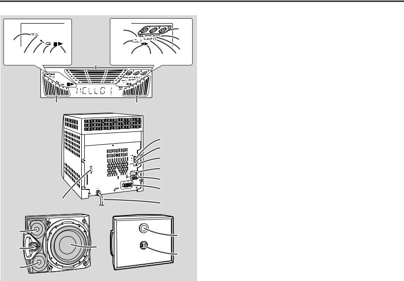
Ñ Rear panel |
|
|
Reference page |
1. FM 75 Ohms Aerial Terminal . . . . . . . . . . . . . . . . . . . . . |
. . . . . . . . .7, 8 |
2. FM Aerial Earth Terminal . . . . . . . . . . . . . . . . . . . . . . . . |
. . . . . . . . .7, 8 |
3. AM Loop Aerial Socket . . . . . . . . . . . . . . . . . . . . . . . . . |
. . . . . . . . .7, 8 |
4. Span Selector Switch . . . . . . . . . . . . . . . . . . . . . . . . . . |
. . . . . . . . . .10 |
5. Video/Auxiliary (Audio Signal) Input Sockets . . . . . . . |
. . . . . . . . . .29 |
6. Speaker Terminals . . . . . . . . . . . . . . . . . . . . . . . . . . . . . |
. . . . . . . . .7, 8 |
7. AC Power Lead . . . . . . . . . . . . . . . . . . . . . . . . . . . . . . . . |
. . . . . . . . . . .9 |
8. AC Voltage Selector . . . . . . . . . . . . . . . . . . . . . . . . . . . . |
. . . . . . . . . . .9 |
Ñ Speaker system |
|
1. Tweeter |
|
2. Super Tweeter |
|
3. Midrange |
|
4. Woofer |
|
5. Bass Reflex Duct |
|
6. Speaker Terminals |
|
E-5 |
ENGLISH |
|
|
|
1
 2
2
 3
3 


 4
4


 5
5
6
7 


 8
8


 9
9 


10 11 12 13
14 
15 
 16
16 
 17
17  18
18  19
19  20
20
21
22
CD-M4000W
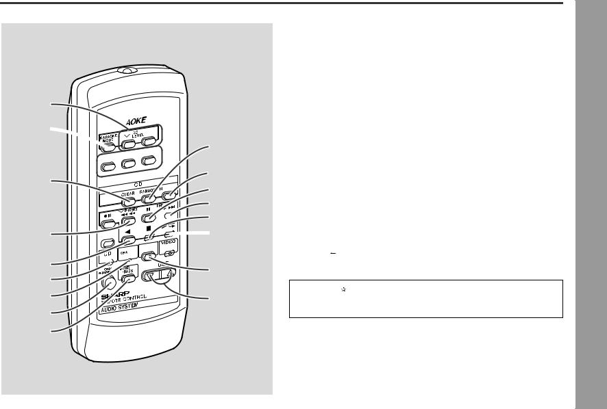
Ñ Remote control |
|
|
|
|
1. Remote Control Transmitter |
Reference page |
|
|
|
. . . . . . . . . . 11 |
|
|
||
2. Echo Level Up and Down Buttons . . . . . . . . . . . . . . . . |
. . . . . . . . . . 22 |
|
|
|
3. Karaoke Mode Button . . . . . . . . . . . . . . . . . . . . . . . . . . |
. . . . . . . . . . 23 |
|
|
|
4. Disc Number Select Buttons . . . . . . . . . . . . . . . . . . . . . . . |
. . . 14, 17, 25 |
|
|
|
5. CD Clear Button . . . . . . . . . . . . . . . . . . . . . . . . . . . . . . . |
. . . . . . . . . 17 |
|
|
|
6. Tape 2 Record Pause Button . . . . . . . . . . . . . . . . . . . . . . |
. . . . . 24 - 26 |
|
|
|
7. CD Track Down or Fast Reverse, Tape 2 Fast Wind, |
|
|
|
|
Tuner Preset Down Button . . . . . . . . . . . . . . . . . . . . . . . . |
. . . 15, 19, 21 |
|
|
|
8. Equalizer Mode Select Button . . . . . . . . . . . . . . . . . . . . . . |
. . . . . . . . . 12 |
Information |
|
|
9. Tape 2 Reverse Play Button . . . . . . . . . . . . . . . . . . . . . . . |
. . . . . . . . . 21 |
-Indicatorsand |
||
10.CD Button |
14, 25 |
|||
|
|
|||
11.Tuner (Band) Button . . . . . . . . . . . . . . . . . . . . . . . . . . . . . |
. . . . . . . . . 18 |
|
|
|
12.On/Stand-by Button . . . . . . . . . . . . . . . . . . . . . . . . . . . . . . |
. . . . . . . . . 11 |
|
|
|
13.Monster Bass Button . . . . . . . . . . . . . . . . . . . . . . . . . . . . . |
. . . . . . . . . 12 |
|
|
|
14.CD Random Button . . . . . . . . . . . . . . . . . . . . . . . . . . . . . |
. . . . . . . . . 16 |
|
|
|
15.CD Memory Button . . . . . . . . . . . . . . . . . . . . . . . . . . . . . . |
. . . . . . . . . 17 |
|
|
|
16.CD Pause Button . . . . . . . . . . . . . . . . . . . . . . . . . . . . . . . |
. . . . . . . . . 15 |
|
|
|
17.CD Track Up or Fast Forward, Tape 2 Fast Wind, |
|
|
|
|
Tuner Preset Up Button . . . . . . . . . . . . . . . . . . . . . . . . . . . |
. . . 15, 19, 21 |
|
|
|
18.CD or Tape Stop Button . . . . . . . . . . . . . . . . . . . . . . . . . . |
. . . 15, 20, 21 |
General |
Controls- |
|
19.CD Play or Repeat, Tape 1 Play, |
|
|||
|
|
|
||
Tape 2 Forward Play Button . . . . . . . . . . . . . . . . . . . . . . . |
15, 16, 20, 21 |
|
|
|
20.Video/Auxiliary Button . . . . . . . . . . . . . . . . . . . . . . . . . . . . |
. . . . . . . . . 29 |
|
|
|
21.Tape (1 2) Button . . . . . . . . . . . . . . . . . . . . . . . . . . . . . . |
. . . 20, 21, 26 |
|
|
|
22.Volume Up and Down Buttons . . . . . . . . . . . . . . . . . . . . . |
. . . . . . . . . 12 |
|
|
Buttons with " " mark in the illustration can be operated on the remote control only.
Other buttons can be operated both on the main unit and the remote control.
|
|
Battery installation for remote control (See page 11.) |
ENGLISH |
E-6 |
|
|
|||
|
|
|

|
|
System Connections |
|
|
FM aerial |
|
|
AM loop aerial |
Use |
- |
|
forPreparation |
ConnectionsSystem- |
Left speaker |
|
|
Right speaker |
|
|
VCR, DVD, etc. |
|
|
not supplied |
|
|
To a wall socket |
|
|
(See page 9.) |
E-7 |
ENGLISH |
|
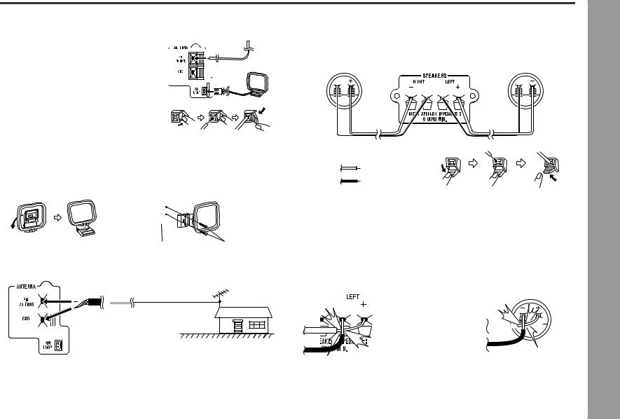
Ñ Aerial connection
Supplied FM aerial:
Connect the FM aerial wire to the FM 75 OHMS terminal and position the FM aerial wire in the direction where the strongest signal can be received.
Supplied AM loop aerial:
Connect the AM loop aerial wire to the AM LOOP socket. Position the AM loop aerial for optimum reception. Place the AM loop aerial on a shelf, etc., or attach it to a stand or a wall with screws (not supplied).
Note:
Placing the aerial on the unit or near the AC power lead may cause noise pickup. Place the aerial away from the unit for better reception.
Installing the AM loop aerial:
< Assembling > < Attaching to the wall >
|
|
Wall |
Screws (not supplied) |
External FM aerial:
Use an external FM aerial if you require better reception. Consult your dealer.
External
FM aerial
75 ohm coaxial cable
Note:
When an external FM aerial is used, disconnect the supplied FM aerial wire.
CD-M4000W
Ñ Speaker connection
Connect the black wire to the minus (-) terminal, and the red wire to the plus (+) terminal.
Right speaker |
|
|
|
|
|
|
|
|
|
|
|
|
|
|
|
Left speaker |
||||||||||||||||||||
|
|
|
|
|
|
|
|
|
|
|
|
|
|
|
|
|
|
|
|
|
|
|
|
|
|
|
|
|
|
|
|
|
|
|
|
|
|
|
|
|
|
|
|
|
|
|
|
|
|
|
|
|
|
|
|
|
|
|
|
|
|
|
|
|
|
|
|
|
|
|
|
|
|
|
|
|
|
|
|
|
|
|
|
|
|
|
|
|
|
|
|
|
|
|
|
|
|
|
|
|
|
|
|
|
|
|
|
|
|
|
|
|
|
|
|
|
|
|
|
|
|
|
|
|
|
|
|
|
|
|
|
|
|
|
|
|
|
|
|
|
|
|
|
|
|
|
|
|
|
|
|
|
|
|
|
|
|
|
|
|
|
|
|
|
|
|
|
|
|
|
|
|
|
|
|
|
|
|
|
|
|
|
|
|
|
|
|
|
|
|
|
|
|
|
|
|
|
|
|
|
|
|
|
|
|
|
|
|
|
|
|
|
|
|
|
|
|
|
|
|
|
|
Use |
- |
Red |
forPreparation |
ConnectionsSystem- |
|
|
|
Black |
|
|
Caution: |
|
|
z Connect the speaker wires to the speakers first, then to the unit. |
|
|
z Use speakers with an impedance of 6 ohms or more, as lower impedance speak- |
|
|
ers can damage the unit. |
|
|
z Do not mistake the right and the left channels. The right speaker is the one on the |
|
|
right side when you face the unit. |
|
|
z Do not let the bare speaker wires touch each other. |
|
|
z Do not allow any objects to fall into or to be placed in the bass reflex ducts. |
|
|
z Do not stand or sit on the speakers. You may be injured. |
|
|
|
|
|
|
|
|
|
|
|
|
|
|
|
|
|
|
|
|
|
|
|
|
|
|
|
|
|
|
|
|
|
|
|
|
|
|
|
|
|
|
|
|
|
|
|
|
|
|
|
|
|
|
|
|
|
|
|
|
|
|
|
|
|
|
|
|
|
|
|
|
|
|
|
|
|
|
|
|
|
|
|
|
|
|
|
|
|
|
|
|
|
|
|
|
|
|
|
|
|
|
|
|
|
|
|
|
|
|
|
|
|
|
|
|
|
|
|
|
|
|
|
|
|
|
|
|
|
|
|
|
|
|
|
|
|
|
|
|
|
|
|
|
|
|
|
|
|
|
|
|
|
|
|
|
|
|
|
|
|
|
|
|
|
|
|
|
|
|
|
|
|
|
|
|
|
|
|
|
|
|
|
|
|
|
|
|
|
|
|
|
|
|
|
|
|
|
|
Incorrect |
|
Incorrect |
||||||||||||||||||||||||||||||||||
|
ENGLISH |
E-8 |
|
|
Preparation for Use - System Connections -
System Connections (continued)
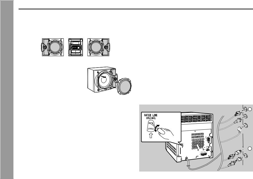
Ñ Placing the speaker system
The left and right speakers have individual shapes. For best performance, place the speakers according to the diagram below.
Left speaker |
Right speaker |
|||||||
|
|
|
|
|
|
|
|
|
|
|
|
|
|
|
|
|
|
|
|
|
|
|
|
|
|
|
|
|
|
|
|
|
|
|
|
|
|
|
|
|
|
|
|
|
Speaker grilles are removable:
Make sure nothing comes into contact with the speaker diaphragms when you remove the speaker grilles.
Note:
Only the grilles on the woofer is removable.
Ñ Setting the AC voltage selector
Check the setting of the AC voltage selector located on the rear panel before plugging the unit into a wall socket. If necessary, adjust the selector to correspond to the AC power voltage used in your area.
Turn the selector with a screwdriver until the appropriate voltage number appears in the window (110 V, 127 V, 220 V or 230 V - 240 V AC).
Ñ Connecting the AC power lead
After making all connections, plug the unit. If you plug the unit first, the unit will enter the demonstration mode (see page 10).
Note:
Unplug the AC power lead from the wall socket if the unit will not be in use for a prolonged period of time.
AC Plug Adaptor
In areas (or countries) where a wall socket as shown in illustration  is used, connect the unit using the AC plug adaptor supplied with the unit, as illustrated. The AC plug adaptor is not included in areas where the wall socket and AC power plug can be directly connected (see illustration
  ).
).
Caution: |
|
|
The metallic handles on the both sides of the speaker grill are decorations. Do not |
1 |
|
carry the speakers by them as this may damage the speakers. |
||
|
 2
2
E-9 |
ENGLISH |
|
|
Demonstration mode (See page 10.) |
|
|
|||
|
|
|
 Loading...