


Carousel II R-3A54

R-3A54
R-2CC”
SHARP
SERVICE MANUAL
S4202R3A54PJ/
MICXOWAVE OVEN
MODELS
R-3A54
Photo R-3A54
R-3E54
In interests of user-safety the oven should be restored to its original
condition and only manufacturer original spare parts must be used.
(RD16101 U)
TABLE OF CONTENTS
Page
GENERAL
IMPORTANT INFORMATION
......................................................................................................
1
CAUTION, MICROWAVE
RADIATION,WARNING
......................................................................................
1
PRODUCT
SPECIFICATIONS
.........................................................................................................................
2
APPEARANCE
VIEW
........................................................................................................................................
3
OPERATION SEQUENCE
.................................................................................................................................
4
FUNCTION
OF
IMPORTANT COMPONENTS
...............................................................................
......................................................................................................................................
...?
............. 5
SERVICING
............. 7
TEST PROCEDURE
...........................................................................................................................................
9
TOUCH
CONTROL
ASSEMBLY ..................................................................................................................
17
COMPONENT
REPLACEMENT AND ADJUSTMENT
PROCEDURE
.....................................................
22
MICROWAVE
MEASUREMENT
/ WIRING DIAGRAM
.....................................................................
..!..
.........................................
28
.......................................................................................................................................
29
PICTORIAL DIAGRAM . ..................................................................................................................................
30
CONTROL PANEL
CIRCUIT
.........................................................................................................................
31
PRlN-I-ED WIRING
DIAGRAM
.....................................................................................................................
32
PARTS LIST
....................................................................................................................................................
33
PACKlNG
AND ACCESSORIES
...................................................................................................................
38
SHARP CORPORATION
All manuals and user guides at all-guides.com
all-guides.com

R-3A54
R-3E54
Photo R-3E54W)
All manuals and user guides at all-guides.com
SERVICE MANUAL
SHARP
MICROWAVE OVEN
R-3A54/ R-3E54
GENERAL IMPORTANT INFORMATION
This Manual has been prepared to provide Sharp Corp. Service
engineers with Operation and Service Information.
It is recommended that service engineers carefully study the
entire text of this manual, so they will be qualified to render
satisfactory customer service.
(RD36106U)
CAUTION
MICROWAVE RADIATION
Service engineers should not be exposed to the micro-
wave energy which may radiate from the magnetron or
other microwave generating devices if it is improperly
used or connected. All input and output microwave
connections, waveguides, flanges and gaskets must be
secured. Never operate the device without a microwave
energy absorbing load attached. Never look into an
open waveguide or antenna while the device is ener-
gized.
(RD36203U)
WARNING
Never operate the oven until the following points are
ensured.
(A)The door is tightly closed.
(B)The door brackets and hinges are not defective.
(C)The door packing is not damaged.
(D)The door is not deformed or warped.
(E) There is not any other visible damage with the oven.
Servicing and repair work must be carried out only by
trained service engineers.
list are used at voltages
All the parts marked 11*11 on parts
more than 250V.
I
(RD5111 Ou)
R-3A54
R-3E54
t>
is:,
PRODUCT SPECIFICATIONS
“4 .
APPEARANCE VIEW
3
f,”
OPERATING SEQUENCE
/1 *
~ ,JF
2 1 s?r’
. “:
,^
* ,‘*y$$
FUNCTION OF IMPORTANT -“
SERVICING AND
S”
g:”
TEST PROCEDURE
,I ,*<
I Y”“-
I .
^ A
“\;
_ *
TOUCH CONT
ASSEMBLY
REPLACEMENT AND
A
“-
> *
: I‘
@) ;
p”,* ”
MICROWAVE MEASUREMENT
SHARP CORPORATION
OSAKA, JAPAN
(RD37201 U)
All manuals and user guides at all-guides.com

R-3A54
R-3E54
PRODUCT SPECIFICATIONS
SPECIFICATION
ITEM
Power Requirements
240 Volts
50 Hertz
DESCRIPTION
Power Consumption
Power Output
Case Dimensions
Single phase, 3 wire earthed
I .3kW Approx. 6.0 A
800W (IEC-705-1988), 650W (AS 2895-l 986)
Operating frequency of 2450M Hz
Width 520mm
._ Height 294mm
Depth 388mm
Cooking Cavity Dimensions
Width 350 mm
Height 197 mm
Depth 368 mm
Turntable diameter
Control Complement
325mm
Touch Control System
Clock( I:00 - 12:59 )
Timer (0 - 99 minutes 99 seconds )
Microwave Power for Variable Cooking
Repetition Rate;
HIGH
. . . . . . . . ..*...................... Full power throughout the cooking time
MEDIUM
HIGH . . . . . . . . . . . . . . . . . . . . . . . . . . . . . . . . . . . . . . .
approx. 70% of Full
Power
MEDIUM . . . . . . . . . . . . . . . . . . . . . . . . . . . . . . . . . . . . . . . . . . . . . . . . . .
approx.
50% of Full Power
MEDIUM LOW . . ..*...............*........*.......... approx. 30% of Full Power
LOW
*..................,.................................,.... approx. 10% of Full Power
AUTO COOK (R-3A54 only)
EASY DEFROST
Set Weight
INSTANT COOK/START
LESS/MORE (R-3A54 only)
AUTO START/CLOCK
POWER LEVEL
INSTANT ACTION (8 menu)
NUMBER”
STOP/CLEAR
Approx. 16.0 kg
,PnA*,n, 1 I
L
,.l”v-rl”I u)
GENERAL INFORMATION
WARNING
THIS APPLIANCE MUST BE EARTHED
IMPORTANT
THE WIRES IN THIS MAINS LEAD ARE COLOURED IN ACCORDANCE WITH THE FOLLOWING CODE:
GREEN-AND-YELLOW
: EARTH
BLUE
: NEUTRAL
BROWN
: LIVE
i
NOTE: Numbers and letters shown after sentences such as “RD44101 U” are for factory use only.
2
All manuals and user guides at all-guides.com
R-3A54
R-3E54
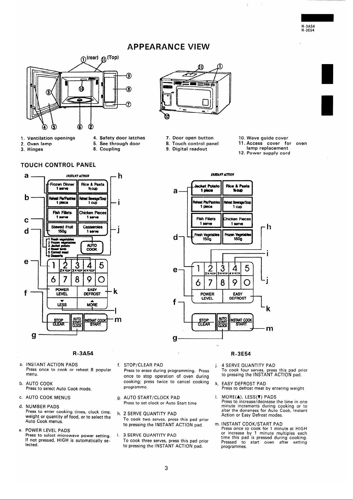
APPEARANCE VIEW
1.
Ventilation
openings 4.
Safety door
latches
2.
Oven lamp
5. See through
door
3.
Hinges
6. Coupling
TOUCH CONTROL PANEL
a-
INSTANT ACnON
-h
d-
e
1
2xw 3xw 4xw
67890
I
-i
4
f--=J-=: I
lE!Ev
t-k
R-3A54
7. Door open button
8. Touch control panel
9. Digital readout
10. Wave guide cover
11. Access cover for oven
lamp replacement
12. Power supply cord
a-
d
1
INSN.NT.UTION
h
I
i
I
2xw 3xw 4xw
67800 “j
R-3E54
a. INSTANT ACTION PADS f. STOP/CLEAR PAD
Press once to cook or reheat 8 popular
j. 4 SERVE QUANTITY PAD
Press to erase during programming. Press
To cook four serves, press this pad prior
menu.
once to stop operation of oven during
to pressing the INSTANT ACTION pad.
b. AUTO COOK
Press to select Auto Cook mode.
c. AUTO COOK MENUS
cooking; press twice to cancel cooking
k. EASY DEFROST PAD
programme.
Press to defrost meat by entering weight
AUTO START/CLOCK PAD
Press to set clock or Auto Start time
d. NUMBER PADS
Press to enter cooking times, clock time,
weight or quantity of food, or to select the
Auto Cook menus.
e. POWER LEVEL PADS
Press to select microwave power setting.
If not pressed, HIGH is automatically se-
lected.
g.
h.
2 SERVE QUANTITY PAD
To cook two serves, press this pad prior
to pressing the INSTANT ACTION pad.
3 SERVE QUANTITY PAD
To cook three serves, press this pad prior
to pressing the INSTANT ACTION pad.
I. MORE(A), LESS(v) PADS
Press to increase/decrease the time in one
minute increments during cooking or to
alter the doneness for Auto Cook, Instant
Action or Easy Defrost modes.
m. INSTANT COOK/START PAD
Press once to cook for 1 minute at HIGH
or increase by 1 minute multiples each
time this pad is pressed during cooking.
Pressed to start oven after setting
programmes.
3
All manuals and user guides at all-guides.com
R -3A54
R-3E54
OPERATING SEQUENCE
OFF CONDITION
Closing the door activates all door interlock switches
(1 st latch switch, 2nd latch switch and stop switch).
IMPORTANT
When the oven door is closed, the monitor switch
contacts (COM -
NC) rnust be open.
When the microwave oven is plugged in a wall outlet.
Rated voltage is supplied to the point A3+ A5 in the
control unit.
1.
3
L.
3.
Figure O-l on page 29
The display flashes “88:88”. -
To set any programmes or set the clock, you must
first touch the STOP/CLEAR key.
11 .
. II appears in the display and the time counts
up every minute.
NOTE: When the oven door is opened, the oven
lamp comes on at this time.
MICROWAVE COOKING CONDITION
HIGH COOKING
Enter a desired cooking time with the touching Number
key and start the oven with touching START key.
Function sequence
1.
2.
3.
4.
5.
Figure O-2 on page 29
CONNECTED COMPONENTS
RELAY
Oven lamp, Fan motor, Turntable motor
RYl
Power transformer
RY2
Rated voltage is supplied to the primary winding of
the power transformer. The voltage is converted to
about 3.3 volts A.C. output on the filament winding
and high voltage of approximately 2000 volts A.C.
on the secondary winding.
The filament winding voltage (3.3 volts) heats the
magnetron filament and the high voltage (2000
volts) is sent to the voltage doubling circuit, where
it is doubled to negative voltage of approximately
4000 volts D.C..
The 2450 MHz microwave energy produced in the
magnetron generates a wave length of 12.24 cm.
This energy is channeled through the waveguide
(transport channel) into the oven cavity, where the
food is placed to be cooked.
When the cooking time is up, a signal tone is heard
and the relays RYI + RY2 go back to their home
position. The circuits to the oven lamp, power
transformer, fan motor and turntable motor are cut
off.
When the door is opened during a cook cycle, the
switches come to the following condition.
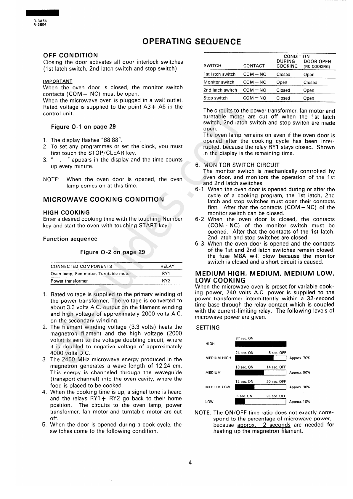
CONDITION
DURING
DOOR OPEN
SWITCH
CONTACT
COOKING (NO COOKING)
1st latch switch
COM - NO
Closed
Open
Monitor switch
COM -NC
Open
Closed
2nd latch switch COM - NO
Closed
Open
Stop switch COM - NO
Closed
Open
The circuits to the power transformer, fan motor and
turntable motor are cut off when the 1st latch
switch, 2nd latch switch and stop switch are made
open.
The oven lamp remains on even if the oven door is
opened after the cooking cycle has been inter-
rupted, because the relay RYI stays closed. Shown
in the display is the remaining time.
6. MONITOR SWITCH CIRCUIT
The monitor switch is mechanically controlled by
oven door, and monitors the operation of the 1 st
and 2nd latch switches.
6-l
When the oven door is opened during or after the
cycle of a cooking program, the 1 st latch, 2nd
latch and stop switches must open their contacts
first. After that the contacts (COM - NC) of the
monitor switch can be closed.
6-2
When the oven door is closed, the contacts
(COM -NC) of the monitor switch must be
opened. After that the contacts of the 1st latch,
2nd latch and stop switches are closed.
6-3. When the oven door is opened and the contacts
of the 1st and 2nd latch switches remain closed,
the fuse M8A will blow because the monitor
switch is closed and a short circuit is caused.
MEDIUM HIGH, MEDIUM, MEDIUM LOW,
LOW COOKING
When the microwave oven is preset for variable cook-
ing power, 240 volts A.C. power is supplied to the
power transformer intermittently within a 32-second
time base through the relay contact which is coupled
with the current-limiting relay. The following levels of
microwave power are given.
SETTING
32 sec. ON
HIGH
MEDIUM HIGH
MEDIUM
MEDIUM LOW
LOW
24 sec. ON 8 sec. OFF
18 sec. ON
14 sec. OFF
J-1 Approx. 50%
12 sec. ON 20 sec. OFF
6 sec. ON 26 sec. OFF
J-1 Approx 10%
NOTE: The ON/OFF time ratio does not exactly corre-
spond to the percentage of microwave power,
because approx. 2 seconds are needed for
heating up the magnetron filament.
All manuals and user guides at all-guides.com
all-guides.com
R-3A54
R-3E54
FUNCTION OF IMPORTANT COMPONENTS
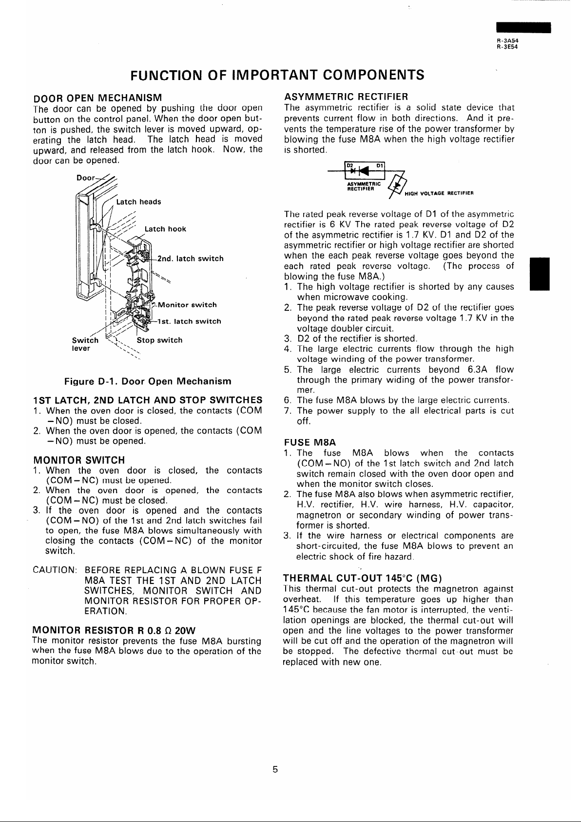
DOOR OPEN MECHANISM
The door can be opened by pushing the door open
button on the control panel. When the door open but-
ton is pushed, the switch lever is moved upward, op-
erating the latch head.
The latch head is moved
upward, and released from the latch hook. Now, the
door can be opened.
Door--&+
Switch
lever
Stop switch
‘.
‘. .\
*.
‘.
Figure D-l. Door Open Mechanism
IST LATCH, 2ND LATCH AND STOP SWITCHES
1. When the oven door is closed, the contacts (COM
2. When the oven door is opened, the contacts (COM
-NO) must be opened.
-NO) must be closed.
MONITOR SWITCH
1. When the oven door is closed, the contacts
(COM-NC) must be opened.
2. When the oven door is opened, the contacts
(COM - NC) must be closed.
3. If the oven door is opened and the contacts
(COM - NO) of the 1st and 2nd latch switches fail
to open, the fuse M8A blows simultaneously with
closing the contacts (COM -NC) of the monitor
switch.
CAUTION: BEFORE REPLACING A BLOWN FUSE F
M8A TEST THE IST AND 2ND LATCH
SWITCHES, MONITOR SWITCH AND
MONITOR RESISTOR FOR PROPER OP-
ERATION.
MONITOR RESISTOR R 0.8 I2 20W
The monitor resistor prevents the fuse M8A bursting
when the fuse M8A blows due to the operation of the
monitor switch.
ASYMMETRIC RECTIFIER
The asymmetric rectifier is a solid state device that
prevents current flow in both directions. And it pre-
vents the temperature rise of the power transformer by
blowing the fuse M8A when the high voltage rectifier
is shorted.
The rated peak reverse voltage of Dl of the asymmetric
rectifier is 6 KV The rated peak reverse voltage of D2
of the asymmetric rectifier is 1.7 KV. Dl and D2 of the
asymmetric rectifier or high voltage rectifier are shorted
when the each peak reverse voltage goes beyond the
each rated peak reverse voltage. (The process of
blowing the fuse M8A.)
1. The high voltage rectifier is shorted by any causes
when microwave cooking.
2. The peak reverse voltage of D2 of the rectifier goes
beyond the rated peak reverse voltage 1.7 KV in the
voltage doubler circuit.
6. The fuse M8A blows by the large electric currents.
7. The power supply to the all electrical parts is cut
off.
3. D2 of the rectifier is shorted.
4. The large electric currents flow through the high
voltage winding of the power transformer.
5. The large electric currents beyond 6.3A flow
through the primary widing of the power transfor-
mer.
FUSE M8A
1. The fuse M8A blows when the contacts
(COM -NO) of the 1 st latch switch and 2nd latch
switch remain closed with the oven door open and
when the monitor switch closes.
2. The fuse M8A also blows when asymmetric rectifier,
H.V. rectifier, H.V. wire harness, H.V. capacitor,
magnetron or secondary winding of power trans-
former is shorted.
3. If the wire harness or electrical components are
short-circuited, the fuse M8A blows to prevent an
electric shock of fire hazard.
THERMAL CUT-OUT 145°C (MG)
This thermal cut-out protects the magnetron against
overheat. If this temperature goes up higher than
145°C because the fan motor is interrupted, the venti-
lation openings are blocked, the thermal cut-out will
open and the line voltages to the power transformer
will be cut off and the operation of the magnetron will
be stopped.
The defective thermal cut-out must be
replaced with new one.
All manuals and user guides at all-guides.com
R-3A54
R-3E54
THERMAL CUT-OUT 145°C (OVEN)
The thermal cut-out located on the top of the oven
cavity is designed to prevent damage to the oven if the
food in the oven catch fire due to over heating
produced by upper setting of cook time or failure of
control unit. Under normal operation, the oven thermal
cut-out remain closed.
However, when abnormally
high temperatures are reached within the oven cavity,
the oven thermal cut-out will open at 145OC, causing
the oven to shut down. The defective thermal cut-out
must be replaced with new one.
TURNTABLE MOTOR
The turntable motor drives coupling to rotate the
turntable.
FAN MOTOR
The fan motor drives a blade which draws external cool
air. This cool air is directed through the air vanes sur-
rounding the magnetron and cools the magnetron.
This air is channeled through the oven cavity to remove
steam and vapors given off from the heating foods. It
is then exhausted through the exhausting air vents at
the oven cavity.
All manuals and user guides at all-guides.com
R-3A54
R-3E54
SERVICING
WARNING TO SERVICE PERSONNEL
Microwave ovens contain circuitry capable of producing very high voltage and current, contact with any part
of the high voltage circuit will result in electrocuition.
REMEMBER TO CHECK 3D
1) Disconnect the supply.
2) Door opened, and wedged open.
3) Discharge high voltage capacitor.
I-
WARNING AGAINST THE CHARGE OF THE
HIGH-VOLTAGE CAPACITOR
The high-voltage capacitor remains charged
about 60 seconds after the oven has been
switched off. Wait for 60 seconds and then
short-circuit
the
connection of
the
high-voltage capacitor (that is, of the con-
necting lead of the high-voltage rectifier)
against the chassis with the use of an insu-
lated screwdriver.
Sharp
recommend
that wherever possible
fault-finding is carried out with the supply discon-
nected. It may in, some cases, be necessary to
connect the supply after the outer case has been
removed, in this event carry out 3lJ checks and then
disconnect the leads to the primary of the power
transformer. Ensure that these leads remain isolated
from other components and the oven chassis. (Use
insulation tape if necessary.) When the testing is
completed carry out 3D checks and reconnect the
leads to the primary of the power transformer.
REMEMBER TO CHECK $lJ
1) Reconnect all leads removed from components
during testing.
2) Replace the outer case (cabinet).
3) Reconnect the supply.
4) Run the oven. Check all functions.
Microwave ovens should not be run empty. To test
for the presence of microwave energy within a
cavity, place a cup of cold water on the oven
turntable, close the door and set the microwave
timer for two (2) minutes. Set the power level to
HIGH and push the START button. When the two
minutes has elapsed (timer at zero) carefully check
that the water is now hot. If the water remains cold
carry out 3lJ checks and re-examine the con-
nections to the component being tested.
When all service work is completed, and the oven is fully assembled, the microwave power output should
be checked and a microwave leakage test carried out.
TROUBLESHOOTING GUIDE
When troubleshooting the microwave oven, it is
helpfull to follow the Sequence of Operation in per-
forming the checks.
Many of the possible causes of
trouble will require that a specific test be performed.
These tests are given a procedure letter which will be
found in the “Test Procedure”section.
IMPORTANT: If the oven becomes inoperative be-
cause of a blown fuse (M8A) in the
1 st latch switch - 2nd latch switch -
monitor switch
- monitor resisitor cir-
cu-it, check the 1st latch switch, 2nd
latch switch, monitor switch and
monitor resistor before replacing the
fuse (M8A).
All manuals and user guides at all-guides.com

R-3A54
R-3E54
RE = Replace / CK = Check
TEST PROCEDURE
P
ii
ii
ii
F
9
-
-
-
-
-
-
-
-
-
-
C
-
-
-
P
L
ONOITION
IFF
:ONDITION
IN
:ONDITION
POSSIBLE
CASE AND
&Xl;ECTIVE
PROBLEM
iome fuse blows when power supply cord is
slugged into wall outlet.
-USE M8A blows when power supply cord is
slugged into wall outlet.
‘88:88” does not appear in display but power
jupply cord is plugged into wall outlet.
3isplay does not operate properly when
STOP/CLEAR key is touched.
3ven lamp does not light at door opened.
: Display appears.)
3ven does not start when the START pad is
ouched. (Display appears)
3ven lamp does not light
:Display appears.)
-an motor does not operate.
(Display appears.)
Turntable motor assembly does not operate.
(Display appears.)
Oven or any electrical parts does not stop
But cooking time is 0 or STOP/CLEAR key
touched
Oven seems to be operating but little or no heat
is produced in oven load. (Microwave power level
is set at HIGH)
-
Oven does not seems to be operating properly
when MEDIUM HIGH, MEDIUM, MEDIUM LOW
or LOW is set. (Oven operates properly at HIGH
and then the STOP/CLEAR pad is touched the
oven stops.)
Oven goes into cook cycle but shuts down before
end of cooking cycle.
Oven stops as soon as when the START pad is
touched.
E
-
E
I
a
i?
+
2
-
-
,
-
-
-
-
-
-
-
-
-
-
-
-
F
-
ii
E
p/1
k
ci
1
ii
1
z
C
-
5
-
-
-
-
-
-
-
-
c
-
3
2
::
E
T
i
:
i!
g
-
c
-
-
-
-
-
-
-
-
-
-
-
T
3
0
;
!i
Y
ER
ii
!i
:
-
-
”
-
v
-
2
-
-
m
-
c
c
-
-
C
-
-
-
3E
c
E
k
F
;
:
5
-
-
-
-
-
-
c:
-
-
-
-
-
-
-
8
All manuals and user guides at all-guides.com
R -3A54
I?-3E54
TEST PROCEDURES
PROCEDURE
LETTER
COMPONENT TEST
A
MAGNETRON TEST
’ NEVER TOUCH ANY PART IN THE CIRCUIT WITH YOUR HAND OR AN INSULATED
TOOL WHILE THE OVEN IS IN OPERATION.
____-- -----_____-_.. __ _____ _ _
CARRY OUT 3D CHECKS
Isolate the magnetron from the high voltage circuit by removing all leads connected to the filament
terminal.
To test for an open circuit filament use an ohmmeter to make a continuity test between the
magnetron filament terminals, the meter should show a reading of less than 1 ohm.
To test for a short circuit filament to anode condition, connect ohmmeter between one of the fil-
ament terminals and the case of the magnetron (ground). This test should be indicated an infinite
resistance. If a low or zero resistance reading is obtained then the magnetron should be re
laced.
(R g 82AOl U)
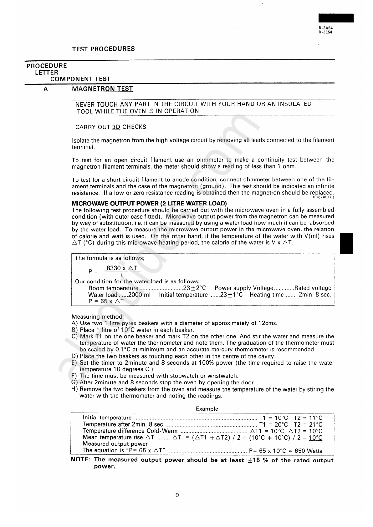
MICROWAVE OUTPUT POWER (2 LITRE WATER LOAD)
The following test procedure should be carried out with the microwave oven in a fully assembled
condition (with outer case fitted). Microwave output power from the magnetron can be measured
by way of substitution, i.e. it can be measured by using a water load how much it can be absorbed
by the water load. To measure the microwave output power in the microwave oven, the relation
of calorie and watt is used. On the other hand, if the temperature of the water with V(ml) rises
AT (“C) during this microwave heating period, the calorie of the water is V x AT.
The formula is as follows;
p=
8330 x AT
t
Our condition for the water load is as follows:
/
Room temperature
. . . . ..*..................... 23 + 2°C Power supply Voltage . . . . . . . . . . . . . Rated voltage /
Water load
. . . ...2000 ml Initial temperature
. . . . ...23&1 “C Heating time . . . . . . . . 2min. 8 sec. j
P=65xAT
Measuring method:
A) Use two 1 litre Pyrex beakers with a diameter of approximately of 12cms.
B) Place 1 litre of 10°C water in each beaker.
C) Mark Tl on the one beaker and mark T2 on the other one. And stir the water and measure the
temperature of water the thermometer and note them. The graduation of the thermometer must
be scaled by 0.1 “C at minimum and an accurate mercury thermometer is recommended.
D) Place the two beakers as touching each other in the centre of the cavity.
E) Set the timer to 2minute and 8 seconds at 100% power (the time required to raise the water
temperature 10 degrees C.)
F) The time must be measured with stopwatch or wristwatch.
G) After 2minute and 8 seconds stop the oven by opening the door.
H) Remove the two beakers from the oven and measure the temperature of the water by stiring the
water with the thermometer and noting the readings.
Example
Initial temperature
Tl = 10°C
T2 =
...............................................................................
11 “C
Temperature after 2min.
8 sec. ..........................................................
Tl =
20°C T2 = 21 “C
Temperature difference Cold-Warm
........................................... AT1 = 10°C
AT2 = 10°C
Mean temperature rise AT ........
AT = (AT1 +AT2) / 2 - (IOOC + IO’C) / 2 = 10°C
Measured output power
The equation is “P= 65 x AT”
...................................................
P= 65 x 10°C = 650 Watts
NOTE: The measured output power should be at least +I5 % of the rated output
power.
All manuals and user guides at all-guides.com
all-guides.com
 Loading...