


UFR41B

Drive Technology \ Drive Automation \ System Integration \ Services
Manual
Fieldbus Gateway UFR41B
EtherNet/IP, Modbus/TCP and PROFINET IO
Edition 05/2009 16798813 / EN
SEW-EURODRIVE—Driving the world

1 General Information ............................................................................................... 7
Phone: 800.894.0412 - Fax: 888.723.4773 - Web: www.clrwtr.com - Email: info@clrwtr.com
1.1 How to use the manual .......... ... .... ... ... ... ....................................... ... ... .... ... .... 7
1.2 Structure of the safety notes .......................................................................... 7
1.3 Rights to claim under limited warranty........................................................... 8
1.4 Exclusion of liability........................................................................................ 8
1.5 Copyright notice............................................................................................. 8
2 Safety Notes ......................... .... ...................................... .... ... ... ... ........................... 9
2.1 Other applicable documentation .................................................................... 9
2.2 General safety notes for bus systems............................................................ 9
2.3 Safety functions ............... ... ... ... .... ...................................... .... ... ... ... ... ........... 9
2.4 Hoist applications....................................................................... ... ... ... .... ... .... 9
2.5 Product names and trademarks.......................................................... .... ....... 9
2.6 Waste disposal............................................................................................. 10
3 Introduction .......................................................................................................... 11
3.1 Content of the manual......................... ... .... ... ... ... ....................................... .. 11
3.2 Characteristics ............................................................................................. 11
3.2.1 Process data exchange .................................................................... 11
3.2.2 Parameter access ............................................................................. 11
3.2.3 Monitoring functions .......................................................................... 12
4 Assembly and Installation Instructions ............................................................. 13
4.1 Installation options of the UFR41B fieldbus gateway................................... 13
4.2 Voltage supply ............................................................................................. 14
4.2.1 Voltage supply in the MOVIAXIS
4.2.2 Voltage supply in the UOH21B gateway housing ............................. 16
4.3 Connecting inverters and engineering-PC................................................... 17
4.3.1 Functional description of the terminals, DIP switches
and LED of the UFR41B option ........................................................ 17
4.3.2 Connecting CAN 1 system bus (X33 connector)/ CAN 2
(X32 connector) ................................................................................ 18
4.3.3 Connecting SBUSplus system bus (terminal X36) ............................ 22
4.3.4 Ethernet interface terminal (terminal X37) ........................................ 22
4.4 Status LED of the UFR41B fieldbus gateway .............................................. 23
4.5 DIP switch S1 default IP address................................................................. 24
4.6 SD memory card type OMG4.B ................................................................... 24
4.7 Connecting the UFR41B fieldbus gateway to an Ethernet network ............. 25
4.8 Pin assignment X30-1, X30-2 and X37........................................................ 25
4.9 Shielding and routing bus cables................................................................. 26
4.10 The integrated Ethernet switch .................................................................... 27
4.11 Setting the DIP switches ..................... ... .... ... ... ... ....................................... .. 28
4.12 Status LED of the UFR41B fieldbus gateway .............................................. 29
4.12.1 Status LED in EtherNet/IP and Modbus/TCP operation ................... 29
4.12.2 Status LED in PROFINET operation ................................................ 30
4.12.3 Link / Activity LEDs .......................................................................... 31
4.13 TCP / IP addressing and subnetworks......................................................... 32
4.14 Setting the IP address parameters............................................................... 34
4.15 Procedure for repla cin g the un it....................................................... ... ......... 36
®
master module ........................... 14
Manual – Fieldbus Gateway UFR41B EtherNet/IP , Modbus/TCP and PROFINET IO
3

Phone: 800.894.0412 - Fax: 888.723.4773 - Web: www.clrwtr.com - Email: info@clrwtr.com
5 Configuring the UFx41B Fieldbus Gateway and Inverter................................. 37
5.1 Description of the gateway functions ........................................................... 37
5.1.1 Introduction ....................................................................................... 37
5.1.2 Autosetup .......................................................................................... 37
5.1.3 Customized configuration ................................................................. 39
5.1.4 Configuring fieldbus gateway and slave units ................................... 40
5.1.5 Data backup ...................................................................................... 42
5.2 Startup procedure ........................................................................................ 45
5.2.1 Checking hardware installation and communication settings ........... 45
5.2.2 Establishing an engineering connection ........................................... 45
5.2.3 Configuring the fieldbus gateways .................................................... 47
5.2.4 Last settings in the slave units .......................................................... 48
5.2.5 Monitoring and controlling process data ........................................... 50
5.2.6 Saving inverter data in the fieldbus gateway
and using MOVITOOLS
5.2.7 Error processing and status messages ............................................. 55
6 Configuration and Startup (EtherNet/IP).......................................................... .. 58
6.1 Validity of the EDS file for UFR41B.............................................................. 58
6.2 Configuring the master (EtherNet/IP scanner)............................................. 59
6.3 Project planning examples in RSLogix 5000 . ...................................... .... ... .. 62
6.3.1 UFR41B fieldbus gateway with 16 PD data exchange ..................... 62
6.3.2 Access to UFR41B fieldbus gateway parameters ............................. 64
6.3.3 Access to unit parameters of lower-level units .................................. 67
®
MotionStudio ............................................ 53
7 Ethernet Industrial Protocol (EtherNet/IP) .................................... ... ... ... ... .... ... .. 70
7.1 Introduction .................................................................................................. 70
7.2 Process data exchange ............................................................................... 70
7.3 CIP object directory...................................................................................... 71
7.4 Return codes of the parameterization via explicit messages....................... 84
8 Configuration and Startup (Modbus/TCP) ....... ... ... ... ... .... ... ... ... .... ... ... ... ... .... ... .. 88
8.1 Unit description file for Modbus/TCP............................................................ 88
8.2 Configuring the master (Modbus scanner)................................................... 88
8.3 Project planning examples in PL7 PRO....................................................... 91
8.3.1 UFR41B fieldbus gateway with 16 PD data exchange ..................... 91
8.4 Examples for data exchange via Modbus/TCP............................................ 92
8.4.1 Writing and reading process data ..................................................... 93
8.4.2 Parameter access ............................................................................. 95
9 Modbus Protocol (Modbus/TCP)......................................................................... 97
9.1 Introduction .................................................................................................. 97
9.1.1 Mapping and addressing .................................................................. 97
9.1.2 Services (function codes) .................................................................. 98
9.1.3 Access .............................................................................................. 98
9.2 Protocol structure......................................................................................... 99
9.2.1 Header .............................................................................................. 99
9.2.2 Service FC3 - Read Holding Registers ........................................... 100
9.2.3 Service FC16 - Write Multiple Registers ......................................... 101
9.2.4 Service FC23 - Read/Write Multiple Registers ............................... 102
9.2.5 Service FC43 - Read Device Identification ..................................... 103
4
Manual – Fieldbus Gateway UFR41B EtherNet/IP, Modbus/TCP and PROFINET IO

9.3 Connection management........................................................................... 104
Phone: 800.894.0412 - Fax: 888.723.4773 - Web: www.clrwtr.com - Email: info@clrwtr.com
9.3.1 Sending process output data (requesting controlling connection) .. 104
9.3.2 Disconnecting connections ............................................................. 105
9.3.3 Timeout monitoring ......................................................................... 105
9.4 Parameter access via Modbus/TCP. ....................................... ... ... ... ... ....... 106
9.4.1 Procedure with FC16 and FC3 ....................................................... 106
9.4.2 Procedure with FC23 ...................................................................... 106
9.4.3 Protocol structure ............................................................................ 107
9.4.4 MOVILINK
9.5 Error codes (exception codes) ................................................................... 109
10 Configuring PROFINET IO....................................................... .......................... 110
10.1 Configuring PROFINET IO co nt ro ller.................................................. .... ... 110
10.1.1 Installing the GSD file .................................................................... 110
10.1.2 Assigning a PROFINET device name ............................................ 111
10.2 Configuring PROFINET connection for UFR41B fieldbus gateway ........... 113
10.2.1 Creating a new project ................................................................... 113
10.2.2 Configuring a station ...................................................................... 115
10.3 PROFINET configuratio n with top ology detection...................................... 117
10.3.1 Introduction .................................................................................... 117
10.3.2 Configuring the PROFINET topology ............................................. 118
10.3.3 Changing the port properties ......................................................... 120
10.3.4 Topology diagnostics ..................................................................... 122
10.3.5 Port statistics .................................................................................. 123
10.4 PROFINET diagnostic alarm s.................................................... ................ 125
10.4.1 Activating diagnostic alarms ........................................................... 125
10.4.2 Determining the cause of an error .................................................. 126
®
parameter channel ...................................................... 108
11 Operating Characteristics (PROFINET IO)....................................................... 127
11.1 Process data exchange with the UFR41B fieldbus gateway...................... 127
11.2 Parameterization via PROFIdrive dataset 47............................................. 129
11.2.1 PROFINET data records ................................................................ 129
11.2.2 Structure of the \PROFINET parameter channel ........................... 132
11.2.3 Parameterization procedure via data set 47 .................................. 133
11.2.4 Processing sequence for controller ................................................ 134
11.2.5 Addressing connected inverters ..................................................... 135
11.2.6 MOVILINK
11.2.7 PROFIdrive parameter orders ........................................................ 141
11.2.8 Example program for SIMATIC S7 ................................................. 146
12 Operating MOVITOOLS
12.1 About MOVITOOLS
12.1.1 Tasks ............................................................................................. 148
12.1.2 Establishing communication with units ........................................... 148
12.1.3 Executing functions with the units .................................................. 148
12.2 First steps .................................................................................................. 149
12.2.1 Starting the software and creating a project ................................... 149
12.2.2 Establishing communication and scanning the network ................. 149
12.3 Communication mode................................................................................ 150
12.3.1 Overview ........................................................................................ 150
12.3.2 Selecting communication mode (online or offline) ......................... 151
®
parameter requests .................................................... 136
®
MotionStudio............... ...................................... .... ... 148
®
MotionStudio ................................. ... .... ................... 148
Manual – Fieldbus Gateway UFR41B EtherNet/IP , Modbus/TCP and PROFINET IO
5

Phone: 800.894.0412 - Fax: 888.723.4773 - Web: www.clrwtr.com - Email: info@clrwtr.com
12.4 Communication via USB (direct)................................................................ 152
12.4.1 Connect the unit with the PC using USB connection cables .......... 152
12.4.2 Installing the drivers ....................................................................... 153
12.4.3 Configuring USB communication ................................................... 153
12.4.4 USB communication parameters ................................................... 155
12.5 Communication via Ethernet...................................................................... 156
12.5.1 Connecting the unit with the PC via Ethernet ................................. 156
12.5.2 Address Editor ............................................................................... 156
12.5.3 Configuring the communication channel via Ethernet .................... 160
12.5.4 Setting communication parameters for SMLP ................................ 161
12.6 Executing function s with the units.......... .... ... ... ... ... .................................... 163
12.6.1 Parameterizing units in the parameter tree .................................... 163
12.6.2 Reading/changing unit parameters ................................................ 163
12.6.3 Starting up the units (online) .......................................................... 164
12.7 Special configura tion an d dia g no stic s tool s ..................... ... .... ................... 164
13 Error Diagnostics............................................................................................... 165
13.1 Error messages of the fieldbus gateway.................................................... 165
13.1.1 General errors of the fieldbus gateway .......................................... 166
13.1.2 Error during process data processing ............................................ 167
13.1.3 Error during unit replacement ......................................................... 168
13.2 Diagnostic procedure for operation on EtherNet/IP and Modbus/TCP ...... 169
13.3 Diagnostic procedure for operation on PROFINET IO............................... 170
13.3.1 Diagnostic problem: The UFR41B fieldbus gateway
does not operate on PROFINET IO ................................................ 171
14 Technical Data.................................................................................................... 172
14.1 General technical data............................................................................... 172
14.2 UFR41B fieldbus gateway.......................................................................... 173
14.3 Dimension drawings................................................................................... 174
14.3.1 Dimension drawing fieldbus gateway UFR41B / UOH21B ............. 174
14.3.2 Dimension drawing MOVIAXIS
15 Appendix............................................................................................................. 176
15.1 Parameter access to lower-level units via EtherNet/IP.............................. 176
15.2 Parameter access to lower-level units via Modbus/TCP or PROFINET .... 177
15.3 Parameter access to lower-level units via engineering interface............... 178
16 Index.................................................................................................................... 179
®
master module MXM / UFR41B . 175
6
Manual – Fieldbus Gateway UFR41B EtherNet/IP, Modbus/TCP and PROFINET IO
General Information
Phone: 800.894.0412 - Fax: 888.723.4773 - Web: www.clrwtr.com - Email: info@clrwtr.com
How to use the manual
1
1 General Information
Manual
1.1 How to use the manual
The manual is part of the product and contains important information on operation and
service. The manual is written for all employees who assemble, install, startup, and
service the product.
The manual must be accessible and legible. Make sure that persons responsible for the
system and its operation, as well as persons who work independently on the unit, have
read through the manual carefully and understood it. If you are unclear about any of the
information in this documentation, or if you require further information, contact SEWEURODRIVE.
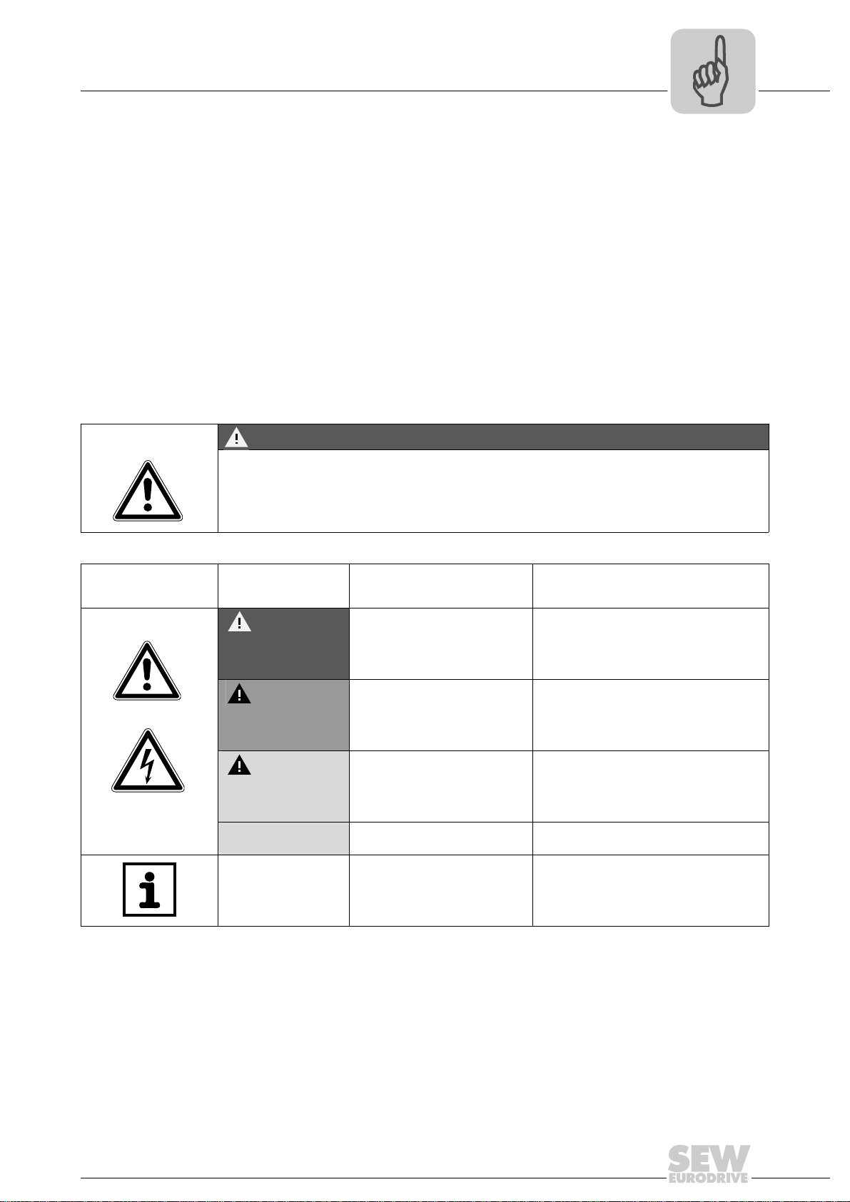
1.2 Structure of the safety notes
The safety notes in this manual are structured as follows:
Pictogram SIGNAL WORD
Type and source of danger.
Possible consequence(s) if the safety notes are disregarded.
• Measure(s) to prevent the danger.
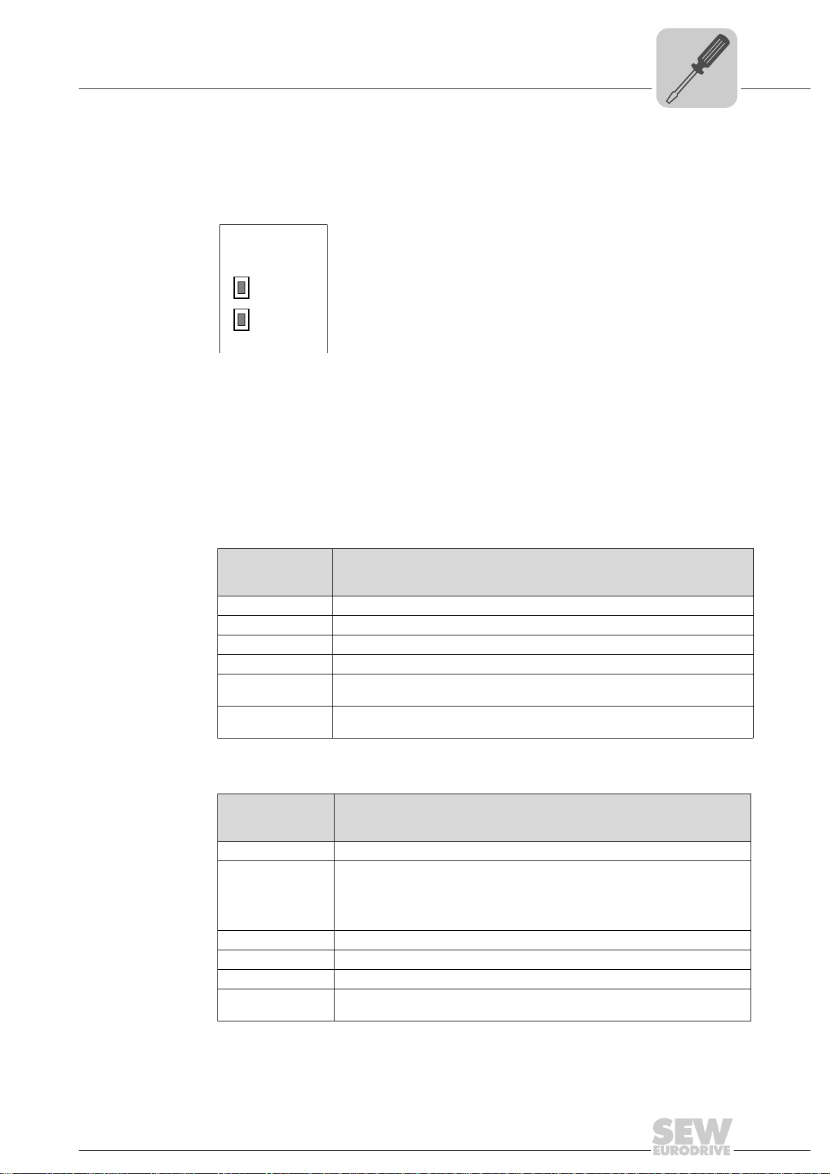
Pictogram Signal word Meaning Consequences if
disregarded
Example:
General danger
Specific danger,
e.g. electric shock
DANGER Imminent danger Severe or fatal injuries
WARNING Possible dangerous situation Severe or fatal injuries
CAUTION Possible dangerous situation Minor injuries
NOTICE Possible damage to property Damage to the drive system or its environ-
ment
TIP Useful information or tip.
Simplifies the handling of the
drive system.
Manual – Fieldbus Gateway UFR41B EtherNet/IP, Modbus/TCP and PROFINET IO
7

1
Phone: 800.894.0412 - Fax: 888.723.4773 - Web: www.clrwtr.com - Email: info@clrwtr.com
General Information
Rights to claim under limited warranty
1.3 Rights to claim under limited warranty
A requirement of fault-free operation and fulfillment of any rights to claim under limited
warranty is that you adhere to the information in the manual. Therefore, read the manual
before you start operating the device.
1.4 Exclusion of liability
You must comply with the information in the manual and the documentation of the units
connected to the fieldbus gateway to ensure safe operation and to achieve the specified
product characteristics and performance features. SEW-EURODRIVE assumes no
liability for injury to persons or damage to equipment or property resulting from nonobservance of the operating instructions. In such cases, any liability for defects is
excluded.
1.5 Copyright notice
© 2008 - SEW-EURODRIVE. All rights reserved.
Copyright law prohibits the unauthorized duplication, modification, distribution, and use
of this document, in whole or in part.
8
Manual – Fieldbus Gateway UFR41B EtherNet/IP, Modbus/TCP and PROFINET IO

Other applicable documentation
Phone: 800.894.0412 - Fax: 888.723.4773 - Web: www.clrwtr.com - Email: info@clrwtr.com
2 Safety Notes
2.1 Other applicable documentation
• Installation and startup may be carried out only by trained personnel observing the
relevant accident prevention regulations and the following documents:
– "MOVIDRIVE
– "MOVITRAC
– "MOVIAXIS
• Read through these documents carefully before you commence installation and
startup of the UFR41B fieldbus gateway.
• As a prerequisite to fault-free operation and fulfillment of warranty claims, you must
adhere to the information in the documentation.
2.2 General safety notes for bus systems
This communication system lets you adjust inverters and servo inverters to a variety of
different applications. As with all bus systems, there is a danger of invisible, external (as
far as the inverter is concerned) modifications to the parameters which give rise to
changes in the unit behavior. This may result in unexpected (not uncontrolled) system
behavior.
®
MDX60B/61B" operating instructions
®
B" operating instructions
®
" operating instructions
Safety Notes
2
2.3 Safety functions
The inverters and servo drives are not allowed to perform any safety functions unless
they are subordinate to other safety systems. Use higher-level safety systems to ensure
protection of equipment and personnel.
For safety applications, ensure that the information in the following publications is
observed: "Safe Disconnection for MOVIDRIVE
2.4 Hoist applications
MOVIDRIVE® MDX60B/61B, MOVITRAC® B and MOVIAXIS® must not be used as a
safety device in hoist applications.
Use monitoring systems or mechanical protection devices as safety equipment to avoid
possible damage to property or injury to people.
2.5 Product names and trademarks
The brands and product names contained within this manual are trademarks or
registered trademarks of the titleholders.
®
B / MOVITRAC® B / MOVIAXIS®".
Manual – Fieldbus Gateway UFR41B EtherNet/IP, Modbus/TCP and PROFINET IO
9

2
Phone: 800.894.0412 - Fax: 888.723.4773 - Web: www.clrwtr.com - Email: info@clrwtr.com
2.6 Waste disposal
Safety Notes
Waste disposal
Observe the applicable national regulations.
Dispose of the following materials separately in accordance with the country-specific
regulations in force, as:
• Electronics scrap
• Plastic
• Sheet metal
• Copper
10
Manual – Fieldbus Gateway UFR41B EtherNet/IP, Modbus/TCP and PROFINET IO

3 Introduction
Phone: 800.894.0412 - Fax: 888.723.4773 - Web: www.clrwtr.com - Email: info@clrwtr.com
3.1 Content of the manual
This user manual describes how to:
• Connect the UFR41B fieldbus gateway to MOVIDRIVE
and to the MOVIAXIS
• Startup MOVIDRIVE
• Startup the fieldbus gateway UFR41B on the fieldbus system EtherNet/IP,
Modbus/TCP and PROFINET IO.
• Configure the EtherNet/IP master with EDS files.
• Configure the Modbus/TCP master.
• Configure the PROFINET IO master using GSD files.
3.2 Characteristics
Introduction
Content of the manual
®
®
servo inverter.
®
B, MOVITRAC® B and MOVIAXIS® for gateway operation.
B, MOVITRAC® B inverters
3
The powerful, universal fieldbus interfaces of the UFR41B fieldbus gateway enable you
to use the option to connect to higher-level automation systems via EtherNet/IP,
Modbus/TCP and PROFINET IO.
3.2.1 Process data exchange
The UFR41B fieldbus gateway allows for digital access to most parameters and
functions via EthernetNet/IP, Modbus/TCP, and PROFINET IO interfaces. Control is
performed via fast, cyclic process data. Via this process data channel, you can enter
setpoints and trigger various control functions, such as enable, normal stop, rapid stop,
etc. At the same time you can also use this channel to read back actual values, such as
actual speed, current, unit status, error number or reference signals.
3.2.2 Parameter access
In EtherNet/IP operation, the parameters of the inverter are set solely via explicit
messages.
In Modbus/TCP operation, the controller can access the parameters via the 8 byte
MOVILINK
In PROFINET operation, two parameter access options are available:
• The PROFIDRIVE data record 47 offers access to all unit information also in
PROFINET operation
• The parameter mechanism offers universal access to any unit information
®
parameter channel.
Manual – Fieldbus Gateway UFR41B EtherNet/IP, Modbus/TCP and PROFINET IO
11

3
Phone: 800.894.0412 - Fax: 888.723.4773 - Web: www.clrwtr.com - Email: info@clrwtr.com
3.2.3 Monitoring functions
Introduction
Characteristics
Using a fieldbus system requires additional monitoring functions, for example, time
monitoring of the fieldbus (fieldbus timeout) or rapid stop concepts. You can determine,
for instance, which fault responses should be triggered in the event of a bus error. The
parameters for the fault response can be set in the servo inverter / inverter. A rapid stop
is useful for many applications. This is why the fieldbus gateway will stop the lower-level
drives in the event of a fieldbus timeout. As the range of functions for the control terminals is also guaranteed in fieldbus mode, you can continue to implement rapid stop
concepts using the servo inverters/inverters connected to the fieldbus gateway.
12
Manual – Fieldbus Gateway UFR41B EtherNet/IP, Modbus/TCP and PROFINET IO
Assembly and Installation Instructions
EURODRIVE
X26
1
23456
7
X24
H1
H2
MOVIAXIS
MOVIAXIS®MXM UFR41B/ UOH21B
UFR41B
2
2
0
1
X35
X36
X30-1
X30-2
X37
XM
1
2
3
1
2
3
1
2
3
1
2
3
X32X33
S1
342
1
L14
L13
T1
L5
L4
L3
L2
L1
ON
1
2
3
X38
L12
L11
UFR41B
2
2
0
1
X35
X36
X30-1
X30-2
X37
XM
1
2
3
1
2
3
1
2
3
1
2
3
X32X33
S1
342
1
L14
L13
T1
L5
L4
L3
L2
L1
ON
1
2
3
X38
L12
L11
Phone: 800.894.0412 - Fax: 888.723.4773 - Web: www.clrwtr.com - Email: info@clrwtr.com
Installation options of the UFR41B fieldbus gateway
4 Assembly and Installation Instructions
4
This chapter contains information on the assembly and installation of the UFR41B fieldbus gateway in a MOVIAXIS
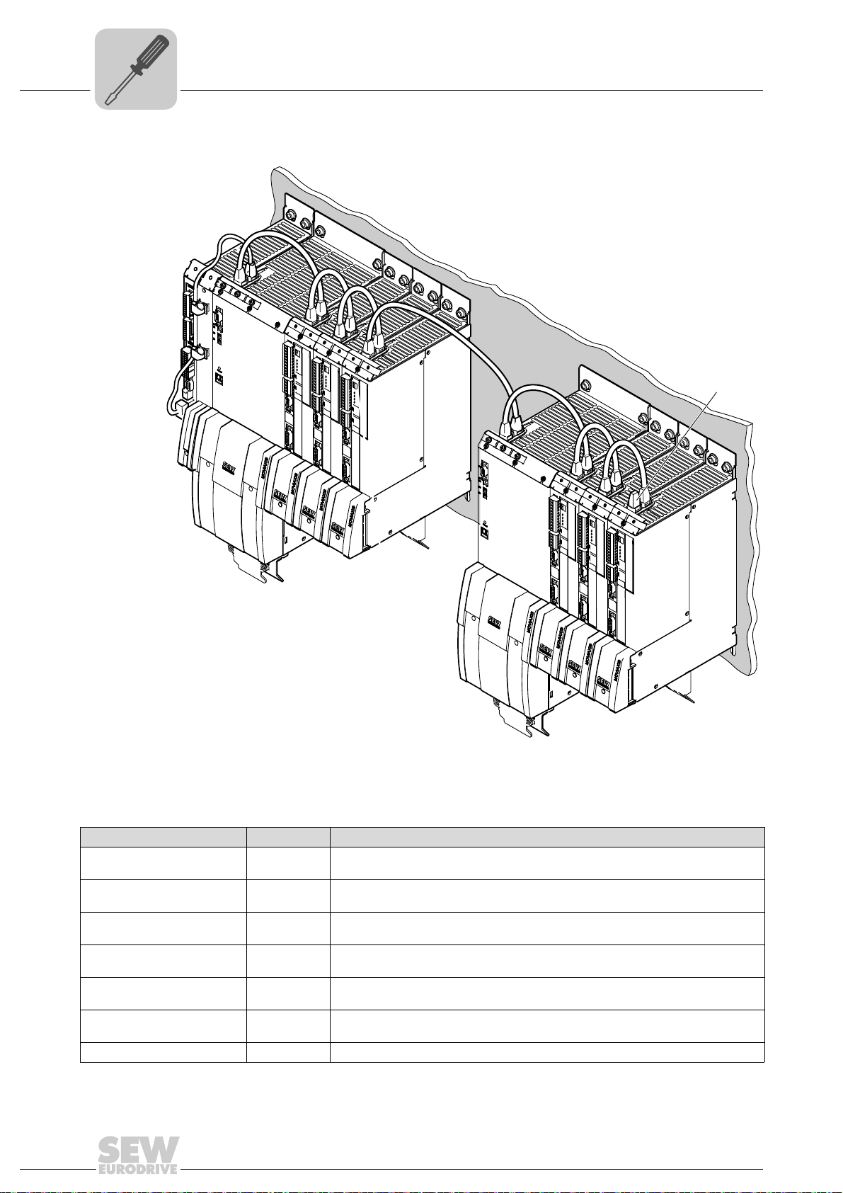
4.1 Installation options of the UFR41B fieldbus gateway
Observe the following installation instructions:
TIP
Only SEW-EURODRIVE is allowed to install/remove the UFR41B fieldbus gateway
into/from a MOVIAXIS
®
master module MXM or in an UOH21B gateway housing.
®
master module MXM and an UOH21B gateway housing.
65055AXX
Manual – Fieldbus Gateway UFR41B EtherNet/IP, Modbus/TCP and PROFINET IO
13
4
Phone: 800.894.0412 - Fax: 888.723.4773 - Web: www.clrwtr.com - Email: info@clrwtr.com
4.2 Voltage supply
Assembly and Installation Instructions
Voltage supply
Voltage supply, system bus and fieldbus interfaces as well as the engineering interface
are located at different potential levels (see chapter 13.1).
4.2.1 Voltage supply in the MOVIAXIS
®
master module
TIP
The MOVIAXIS® master module MXM provides additional connections, which are
described in the following section.
Functional description of the terminals, X5a/X5b (MOVIAXIS
MOVIAXIS® master
module MXM
1
X5b
2
3
4
1
X5a
2
3
4
59233AXX
• The X5a and X5b connectors are connected in parallel. In this way, the voltage
supply of the MOVIAXIS
from below to X5a. With connection to X5a, further modules can be connected via
X5b (e.g. supply module, axis module). The voltage supply for the brake (X5a/b:3, 4)
is fed through the MOVIAXIS
• The UFR41B fieldbus gateway can be supplied from the MOVIAXIS
power supply (MXS) or from an external voltage source. To do so, connect X5
between the individual units.
• If the UFR41B fieldbus gateway is connected with DC 24 V from the MOVIAXIS
switched-mode power supply, the functioning of the option is maintained after disconnection from the power supply. This is the case if the DC link voltage is maintained or an external DC 24 V supply is present from the MOVIAXIS
power supply.
Designation Terminal Function
X5b connector X5b:1
X5a connector X5a:1
®
X5b:2
X5b:3
X5b:4
X5a:2
X5a:3
X5a:4
master module can be provided from the right to X5b or
®
master module.
®
master module)
DC 24 V
DGND
DC 24 V
BGND
DC 24 V
DGND
DC 24 V
BGND
Voltage supply for control electronics
E
Reference potential for control
electronics
B
Voltage supply for brake
Reference potential for brake
connection
Voltage supply for control electronics
E
Reference potential for control
electronics
B
Voltage supply for brake
Reference potential for brake
connection
®
switched-mode
®
switched-mode
®
14
Manual – Fieldbus Gateway UFR41B EtherNet/IP, Modbus/TCP and PROFINET IO
Wiring diagram
MOVIAXIS®
master module MXM
2
X5b
1
DC 24V
E
DGND
3
DC 24V
B
4 BGND
DC 24 V for
brake supply
DC 24 V supply
for control electronics
+-+-
X16
-
+
DC 24 V external
X5a
2
1
3
4
X5a
2
1
3
4
X5b
2
1
3
4
MOVIAXIS®
switched-mode
power supply MXS
UFR41B
2
2
0
1
X35
X36
X30-1
X30-2
X37
XM
1
2
3
1
2
3
1
2
3
1
2
3
X32X33
S1
342
1
L14
L13
T1
L5
L4
L3
L2
L1
ON
1
2
3
X38
L12
L11
Phone: 800.894.0412 - Fax: 888.723.4773 - Web: www.clrwtr.com - Email: info@clrwtr.com
Assembly and Installation Instructions
Voltage supply
4
65056AEN
Manual – Fieldbus Gateway UFR41B EtherNet/IP, Modbus/TCP and PROFINET IO
15
4
X24
H1
H2
Phone: 800.894.0412 - Fax: 888.723.4773 - Web: www.clrwtr.com - Email: info@clrwtr.com
Assembly and Installation Instructions
Voltage supply
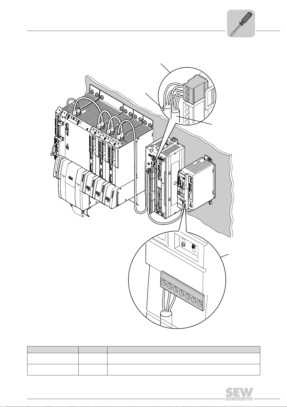
4.2.2 Voltage supply in the UOH21B gateway housing
Description of the terminals and LED functions
Front view
MOVITRAC
compact controller
Side view
Compact controller
X26
2345671
®
B /
58905AXX
58906AXX
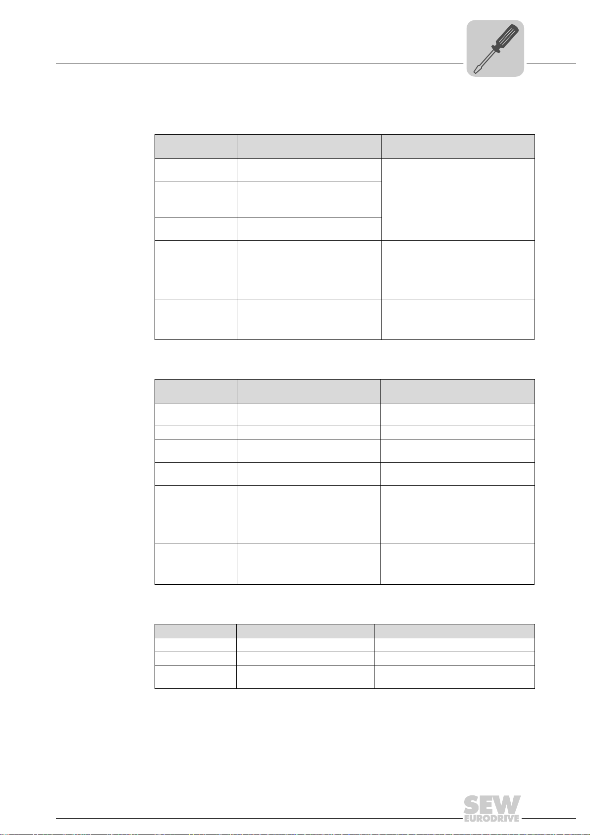
X26:1
X24:2
X24:3
X24:4
X26:5
X26:6
X26:7
LED
Terminal
H2
X24:4
X24:3
X24:2
X24:1
CAN1H
CAN1L
DGND
Reserved
Reserved
DGND
DC 24 V
Function
Reserved
Reserved
No function.
Engineering cannot be
performed using X24.
System bus CAN 1 high
System bus CAN 1 low
Reference potential control/CAN1
-
Reference potential for UFx41B
Voltage supply for controller
Designation
LED H1
X24 connector:
RJ10 socket
Designation Terminal Function
X26 connector:
CAN 1 and
voltage supply
(plug-in terminal)
Connection of CAN 1 system bus / voltage supply (X26 connector)
The connections for CAN 1 (X26:1/2/3 and connector X33) are connected in parallel.
The UFR41B fieldbus gateway is supplied with voltage in the UOH21B gateway housing
via X26:6/7.
16
Manual – Fieldbus Gateway UFR41B EtherNet/IP, Modbus/TCP and PROFINET IO
Assembly and Installation Instructions
UFF41B
X35
X36
X37
Version
1
2
3
1
342
1
2
3
1
2
3
1
2
3
X32X33
S1
L1 L2 L3L5
XM
L4
T1
UFR41B
Phone: 800.894.0412 - Fax: 888.723.4773 - Web: www.clrwtr.com - Email: info@clrwtr.com
Connecting inverters and engineering-PC
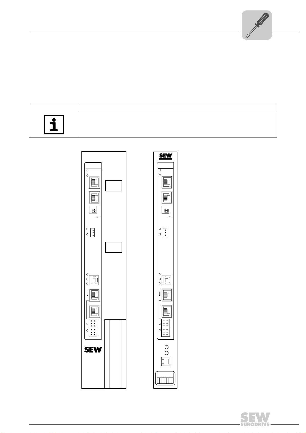
4.3 Connecting inverters and engineering-PC
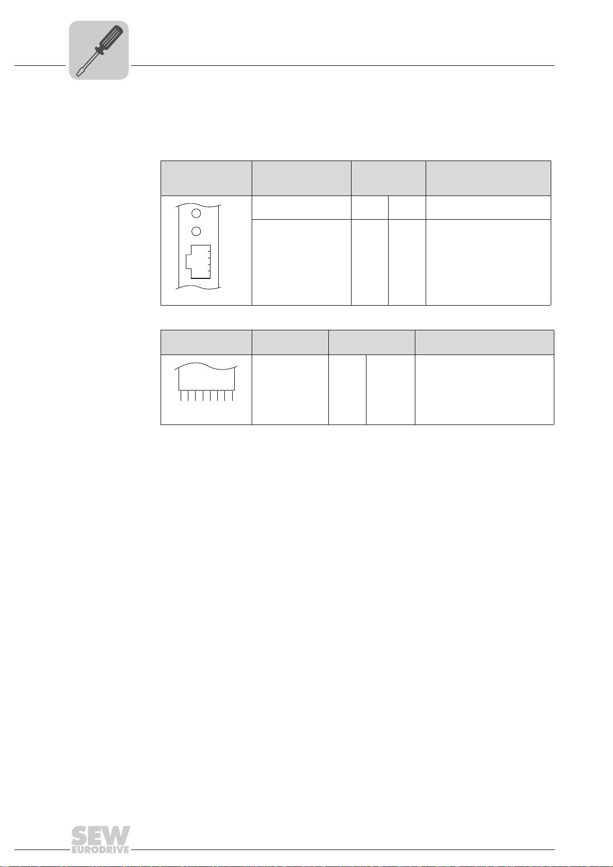
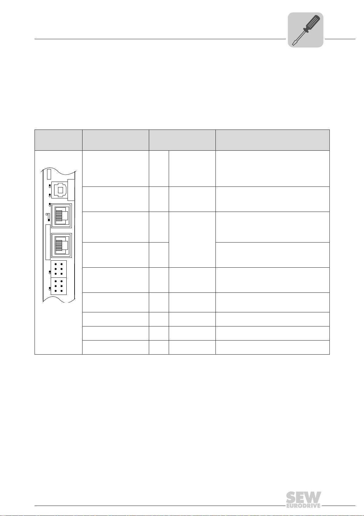
4.3.1 Functional description of the terminals, DIP switch es and LED of the UFR41B option
Connectors, LEDs and DIP switches in the upper area of the UFR41B fieldbus gateway
allow for connection to EtherNet/IP (see chapter "Connecting the UFR41B fieldbus system to an EtherNet/IP network"), Modbus/TCP (see chapter "Connecting the UFR41B
fieldbus to a Modbus/TCP network") and PROFINET IO fieldbus systems (see chapter
"Connecting the UFR41B fieldbus gateway to a PROFINET IO network")
4
Front view
UFR41B fieldbus
gateway
64418AXX
LED
Designation
DIP switch
Terminal
LED LED 1
LED 2
LED 3
LED 4
LED 5
X35 connector:
USB connection
X35:1
X35:2
X35:3
X35:4
X36 connector:
X36
Connection of an EtherCAT based
system bus (RJ45 socket)
X37 connector:
X37 Ethernet for engineering
Ethernet connection
(RJ45 socket)
X32 connector:
System bus CAN 2
(electrically isolated)
X32:1
X32:2
X32:3
(plug-in terminals)
X33 connector:
System bus CAN 1
(plug-in terminals)
X33:1
X33:2
X33:3
DIP switch S1
Memory card M1
Button T1
CAN 1 status
CAN 2 status
Program status
Gateway status
Gateway error
USB+5 V
USBUSB+
DGND
Standard Ethernet
assignment
BZG_CAN 2
CAN 2H
CAN 2L
DGND
CAN 1H
CAN 1L
To p
Bottom
Function
Status of CAN 1 system bus
Status of CAN 2 system bus
Status of gateway program
Status of gateway firmware
Status of gateway error (see section "Error messages of the fieldbus gateway")
DC 5 V voltage supply
USB- signal
USB+ signal
Reference potential
plus
System bus SBUS
(in preparation)
Reference potential for system bus CAN 2
System bus CAN 2 high
System bus CAN 2 low
Reference potential for system bus CAN 1
System bus CAN 1 high
System bus CAN 1 low
Default IP address (192.168.10.4)
IP parameter from SD memory card
Memory for firmware, gateway application,
gateway configuration, and inverter parameters
For Bootloader update
(see section "SD memory card OMG4.B")
Manual – Fieldbus Gateway UFR41B EtherNet/IP, Modbus/TCP and PROFINET IO
17
4
UFF41B
DGND
MDX60B/61B
X12
SC11
2
1
3
SC12
UFR41B
X31X32X33
1
2
3
1
2
3
1
2
3
2
3
1
ON OFF
S12
X45
X46
1
23456HL
FSC11B
MOVITRAC® B
S1
OFF
ON
7
S2
X44
Phone: 800.894.0412 - Fax: 888.723.4773 - Web: www.clrwtr.com - Email: info@clrwtr.com
Assembly and Installation Instructions
Connecting inverters and engineering-PC
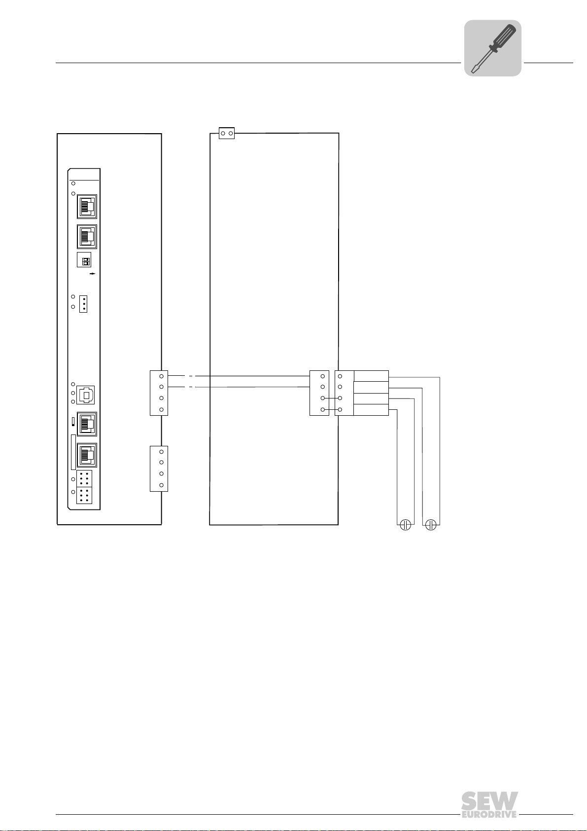
4.3.2 Connecting CAN 1 system bus (X33 connector)/ CAN 2 (X32 connector)
Do not connect more than 16 units to the CAN 1 or CAN 2 system bus in gateway
operation.
TIPS
• The CAN 1 system bus is not electrically isolated. Therefore, it is recommended to
use the CAN 1(X33 or X26 with UFR41B/UOH21B) interface to connect inverters
via the system bus in the control cabinet. Set the P881 SBus address parameter in
increasing order to values 1 - 16 if the slave unit is connected to CAN 1 or the fieldbus gateway.
• The CAN 2 system bus is electrically isolated. Therefore, preferably use interface
CAN 2 (X32) for connecting field units or units in other control cabinets. Set the
P881 SBus address parameter in increasing order to values 17 - 34 if the unit is
connected to CAN 2 or the fieldbus gateway.
The CAN system bus supports transmission systems compliant with ISO 11898. For
detailed information on the CAN system bus, refer to the "MOVIDRIVE
®
Communication
and Fieldbus Device Profile" manual. You can order this manual from SEWEURODRIVE.
®
Wiring diagram for MOVIDRIVE
B, MOVITRAC® B on CAN 1 system bus
64714AXX
Cable specification • Use a 2 x 2-core twisted and shielded copper cable (data transmission cable with
braided copper shield). Clamping without conductor end sleeves is possible in accordance with IEC 60999. The cable must meet the following specifications:
2
– Cable cross-section 0.2 to 1.0 mm
(AWG 24 - AWG 18)
– Cable resistance 120 Ω at 1 MHz
Cable length • The permitted total cable length depends on the baud rate setting of the system bus:
– Capacitance per unit length = 40 pF/m at 1 kHz
Suitable cables include CAN bus or DeviceNet cables.
– 125 kBd → 500 m
– 250 kBd → 250 m
– 500 kBaud → 100 m
– 1000 kBd → 40 m
18
Manual – Fieldbus Gateway UFR41B EtherNet/IP, Modbus/TCP and PROFINET IO
Assembly and Installation Instructions
Phone: 800.894.0412 - Fax: 888.723.4773 - Web: www.clrwtr.com - Email: info@clrwtr.com
Connecting inverters and engineering-PC
4
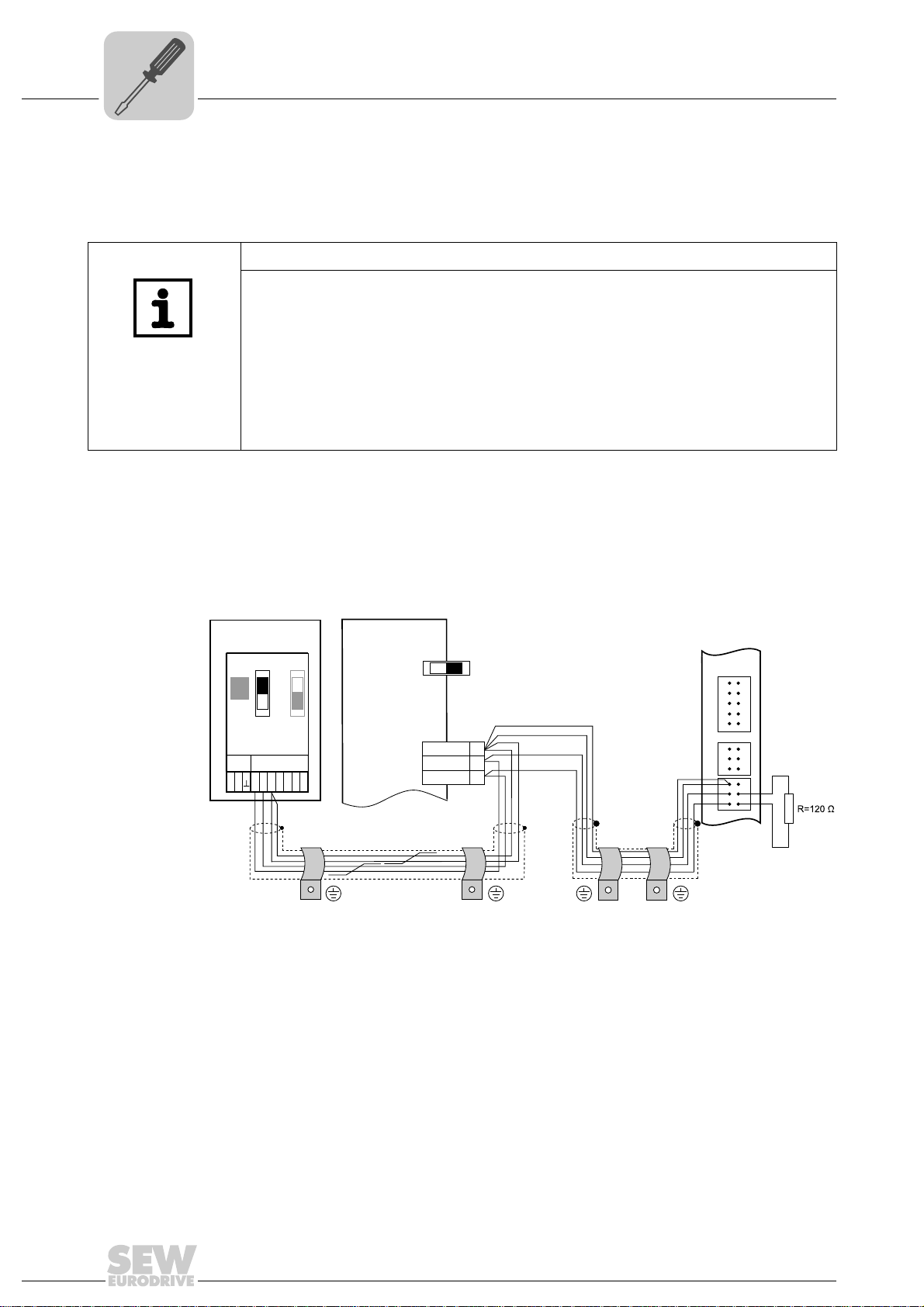
Terminating
resistor
• Switch on the system bus terminating resistor at the start and end of the CAN system
bus connection (MOVIDRIVE
S1 = ON). For all other devices, switch off the terminating resistor (MOVIDRIVE
DIP switch S12 = OFF; MOVITRAC
way is, for example, located at the end of the CAN 2 system bus, you have to connect
a terminating resistor of 120 Ω between pins X32:2 and X32:3 (for CAN 1: terminating
resistor between pins X33:2 and X33:23).
®
B, DIP switch S12 = ON; MOVITRAC® B, DIP switch
®
B, DIP switch S1 = OFF). If the fieldbus gate-
®
B,
CAUTION
•There must not be any potential displacement between the units connected via the
CAN 2 system bus.
•There must not be any potential displacement between the units connected via the
CAN 1 system bus.
• Take suitable measures to avoid potential displacement, such as connecting the
unit ground connectors using a separate cable.
Manual – Fieldbus Gateway UFR41B EtherNet/IP, Modbus/TCP and PROFINET IO
19
4
0
1
0
1
0
1
0
1
0
1
0
1
[1]
Phone: 800.894.0412 - Fax: 888.723.4773 - Web: www.clrwtr.com - Email: info@clrwtr.com
Assembly and Installation Instructions
Connecting inverters and engineering-PC
Wiring diagram for MOVIAXIS® on CAN 1 system bus
[1] Terminating resistor
Overview of system connection cables
Type Part number Description
CAN system cable 0819 692 3
CAN1 connection cable,
750 mm, RJ45-RJ45
CAN1 connection cable,
3000 mm, RJ45-RJ45
CAN2 adapter cable 1810 1607
CAN2 connection cable 1810 1585
CAN2 connection cable 1810 1593
Terminating resistor CAN 2 1810 1615 Terminating resistor for CAN 2 connections between axis modules
20
System cable UFR41B gateway CAN 1 post connector (or CAN 2) to MOVIAXIS
supply/regenerative power module CAN 1 system bus RJ45, length: 750 mm
0819 7261
0819 8993
CAN1 connection cable between MOVIAXIS
system, length: 750 mm
CAN1 connection cable between MOVIAXIS
system, length: 3000 mm
CAN2 post connector between master module and CAN2 SUB-D9 MOVIAXIS
length: 500 mm
CAN2 SUB-D9 MOVIAXIS
modules
CAN2 SUB-D9 MOVIAXIS
®
and CAN2 SUB-D9 MOVIAXIS®, to connect 3 axis
®
and CAN2 SUB-D9 MOVIAXIS®, to connect 4 axis
®
axis system and MOVIAXIS® axis
®
axis system and MOVIAXIS® axis
modules
Manual – Fieldbus Gateway UFR41B EtherNet/IP, Modbus/TCP and PROFINET IO
64784AXX
®
®
,
Assembly and Installation Instructions
X46
ON
OFF
S
2
S
1
1
2
3
4
5
6
7
0
1
0
1
0
1
X12
MOVIAXIS
®
MOVITRAC
®
MOVIDRIVE
®
123
MOVITRAC
®
Phone: 800.894.0412 - Fax: 888.723.4773 - Web: www.clrwtr.com - Email: info@clrwtr.com
Connecting inverters and engineering-PC
Wiring diagram for MOVIAXIS®, MOVIDRIVE® B and MOVITRAC® B on CAN 1 system bus
4
Overview of system connection cables
Type Part number Description
CAN1 connection cable,
750 mm, RJ45 litz wire
CAN1 connection cable,
3000 mm, RJ45 litz wire
0819 7288
0819 7563
CAN connection cable MOVIAXIS
length: 750 mm
CAN connection cable MOVIAXIS
length: 3000 mm
®
axis system to MOVIDRIVE® and MOVITRAC®,
®
axis system to MOVIDRIVE® and MOVITRAC®,
Manual – Fieldbus Gateway UFR41B EtherNet/IP, Modbus/TCP and PROFINET IO
64783AXX
21
4
Phone: 800.894.0412 - Fax: 888.723.4773 - Web: www.clrwtr.com - Email: info@clrwtr.com
Assembly and Installation Instructions
Connecting inverters and engineering-PC
4.3.3 Connecting SBUS
plus
system bus (terminal X36)
Terminal X36 is intended for connecting a system bus based on EtherCAT (SBUS
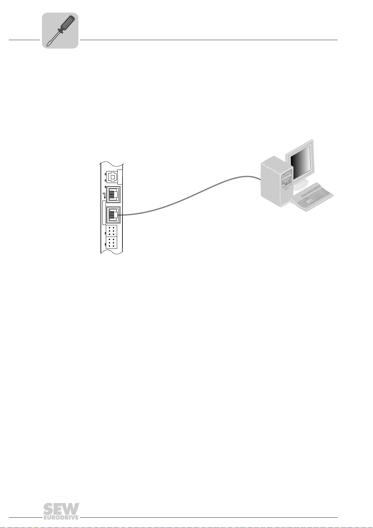
4.3.4 Ethernet interface terminal (terminal X37)
You can connect an engineering PC to the Ethernet interface (terminal X37).
UFF41B
UFR41B
X35
342
1
Version
X36
S1
X37
1
1
XM L4
2
2
X32X33
3
3
1
1
2
2
3
3
L1 L2 L3L5
plus
).
65057AXX
The Ethernet interface (X37) supports auto crossing auto negotiation for baud rate and
duplex mode. The IP parameters are defined depending on DIP switch S1 (see section
"DIP switches S1 default IP address").
In addition to the engineering access via terminal X37, there is another engineering
access via PROFIBUS (see section "Operation of MOVITOOLS
®
MotionStudio").
22
Manual – Fieldbus Gateway UFR41B EtherNet/IP, Modbus/TCP and PROFINET IO
Assembly and Installation Instructions
Phone: 800.894.0412 - Fax: 888.723.4773 - Web: www.clrwtr.com - Email: info@clrwtr.com
Status LED of the UFR41B fieldbus gateway
4.4 Status LED of the UFR41B fieldbus gateway
4
LED L1 (CAN 1
status)
LED L2 (CAN 2
status)
The LED L1 indicates the status of the CAN 1 system bus.
Status of the L1
LED
Orange The CAN 1 system bus is being
Green The CAN 1 system bus is initialized.
Flashing green
(0.5 Hz)
Flashing green
(1 Hz)
Red The CAN 1 system bus is off (BUS-
Flashing red
(1 Hz)
Diagnostics Remedy
initialized.
The CAN 1 system bus is currently in
SCOM suspend mode.
The CAN 1 system bus is currently in
SCOM On mode.
OFF).
Warning on the CAN 1 system bus. 1. Check and correct the cabling of the
-
1. Check and correct the cabling of the
CAN 1 system bus.
2. Check and correct the baud rate set
for the CAN 1 system bus.
3. Check and correct the terminating
resistors of the CAN 1 system bus.
CAN 1 system bus.
2. Check and correct the baud rate set
for the CAN 1 system bus.
The LED L2 indicates the status of the CAN 2 system bus.
Status of the L2
LED
Orange The CAN 2 system bus is being
Green The CAN 2 system bus is initialized. -
Flashing green
(0.5 Hz)
Flashing green
(1 Hz)
Red The CAN 2 system bus is off (BUS-
Flashing red
(1 Hz)
Diagnostics Remedy
initialized.
The CAN 2 system bus is currently in
SCOM suspend mode.
The CAN 2 system bus is currently in
SCOM On mode.
OFF).
Warning on the CAN 2 system bus. 1. Check and correct the cabling of the
-
-
-
1. Check and correct the cabling of the
CAN 2 system bus.
2. Check and correct the baud rate set
for the CAN 2 system bus.
3. Check and correct the terminating
resistors of the CAN 2 system bus.
CAN 2 system bus.
2. Check and correct the baud rate set
for the CAN 2 system bus.
LED L3 (program
status)
LED L3 indicates the status of the gateway program.
Status of L3 Diagnostics Remedy
Green Gateway program is running. -
Off No gateway program is loaded. Load a gateway program into the controller.
Flashing orange
(1 Hz)
Program has stopped. Bootloader update required (see section
"SD memory card type OMG4.B")
Manual – Fieldbus Gateway UFR41B EtherNet/IP, Modbus/TCP and PROFINET IO
23
4
Phone: 800.894.0412 - Fax: 888.723.4773 - Web: www.clrwtr.com - Email: info@clrwtr.com
Assembly and Installation Instructions
DIP switch S1 default IP address
LED 4 (PLC
status)
LED L4 indicates the firmware status of the fieldbus gateway.
Status of the L4 LED Diagnostics Remedy
Flashing green
(1 Hz)
Red • No SD card plugged in.
Flashing orange
(1 Hz)
The firmware of the fieldbus gateway
is running properly.
-
• File system of the SD card
corrupt.
Program has stopped. Bootloader update required (see section
"SD memory card type OMG4.B")
LED L5 (user) LED L5 is lit up red if the gateway program has detected an error and if this error can
®
only be eliminated after diagnostics with MOVITOOLS
MotionStudio.
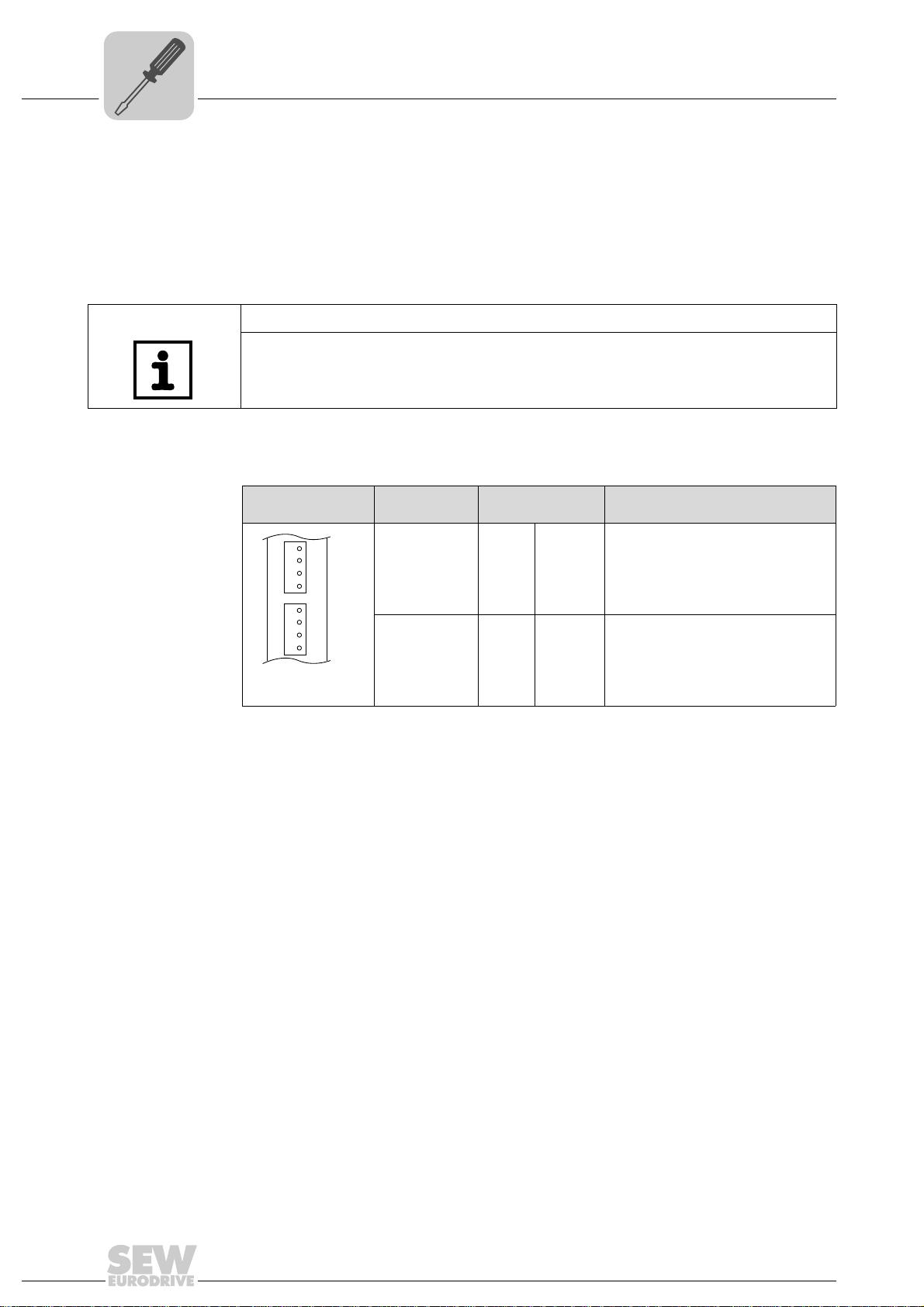
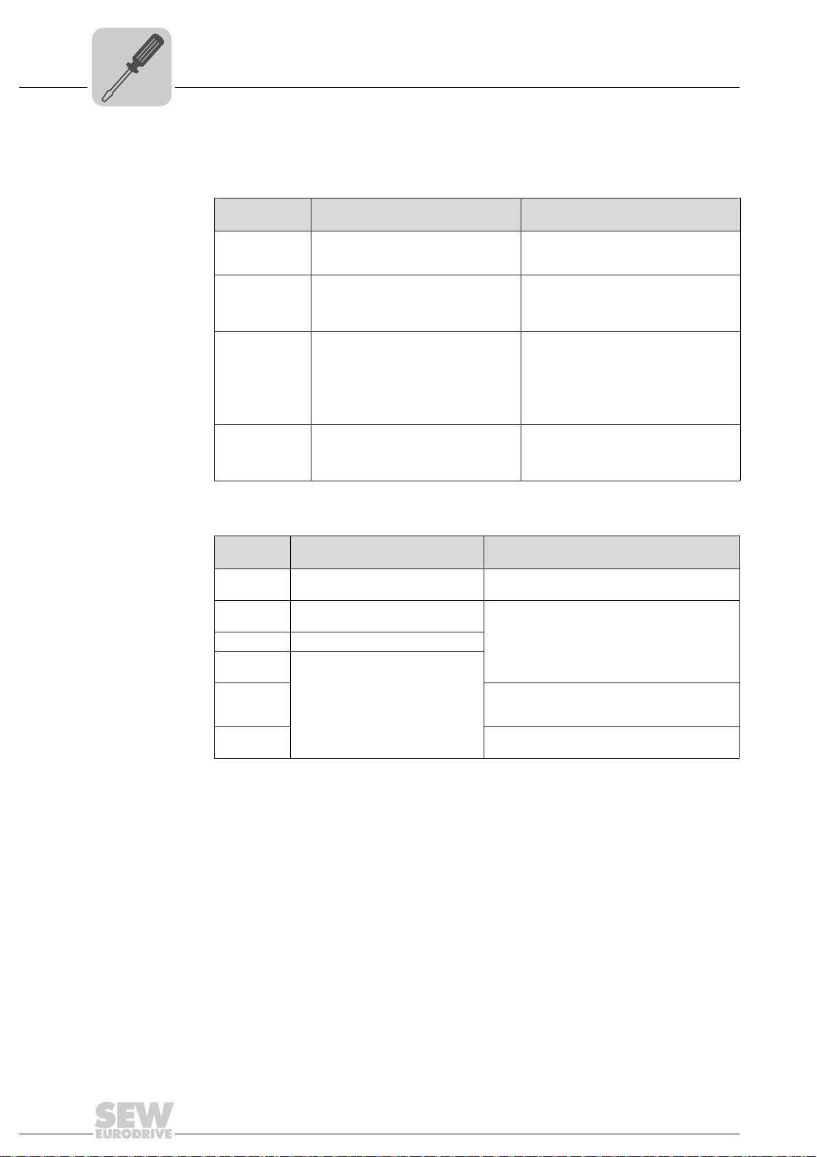
4.5 DIP switch S1 default IP address
With DIP switch S1, you can set a default IP address for the Ethernet connection (X37).
The set IP address is applied in the next boot process.
S1 switch setting Meaning
Top IP p a r am e t e r :
Bottom The IP parameters defined on the memory card of the UFR41B gateway are used.
• IP address: 192.168.10.4
• Subnet mask: 255.255.255.0
• Standard gateway: 1.0.0.0
The IP parameters for engineering interface X37 are entered in the file '...\System\NetConfig.cfg' in section 'Ethernet 2'. You can adjust the file using a text editor
(e.g. Notepad).
4.6 SD memory card type OMG4.B
The SD memory card type OMG4.B is required for operating the UFR41B fieldbus gate-
Bootloader
update
way and contains the firmware, the gateway program, and the gateway configuration.
With a MOVIAXIS
terization in case an axis needs to be replaced.
The SD memory card type OMG4.B is included in the scope of delivery of the UFR41B
fieldbus gateway.
Only use type OMG4.B memory cards in a UFR41B fieldbus gateway.
When the LEDs L3 and L4 flash orange at a 1 Hz frequency after power-on, a bootloader
update is required. Proceed as follows:
• Do not switch off the power supply during the entire process.
• Press the reset button T1 on the front of the UFR41B fieldbus gateway for 3 seconds.
When the bootloader update starts, only LED 4 is flashing.
• The bootloader update has been successful when L4 flashes green.
®
axis module, it is also used for data backup and automatic parame-
24
Manual – Fieldbus Gateway UFR41B EtherNet/IP, Modbus/TCP and PROFINET IO
Assembly and Installation Instructions
UFR41B
2
2
0
1
X30-1
X30-2
L14
L13
ON
1
2
3
X38
L12
L11
[3]
[2]
[1]
2
3
6
1
[6]
AB
Phone: 800.894.0412 - Fax: 888.723.4773 - Web: www.clrwtr.com - Email: info@clrwtr.com
Connecting the UFR41B fieldbus gateway to an Ethernet network
4.7 Connecting the UFR41B fieldbus gateway to an Ethernet network
4
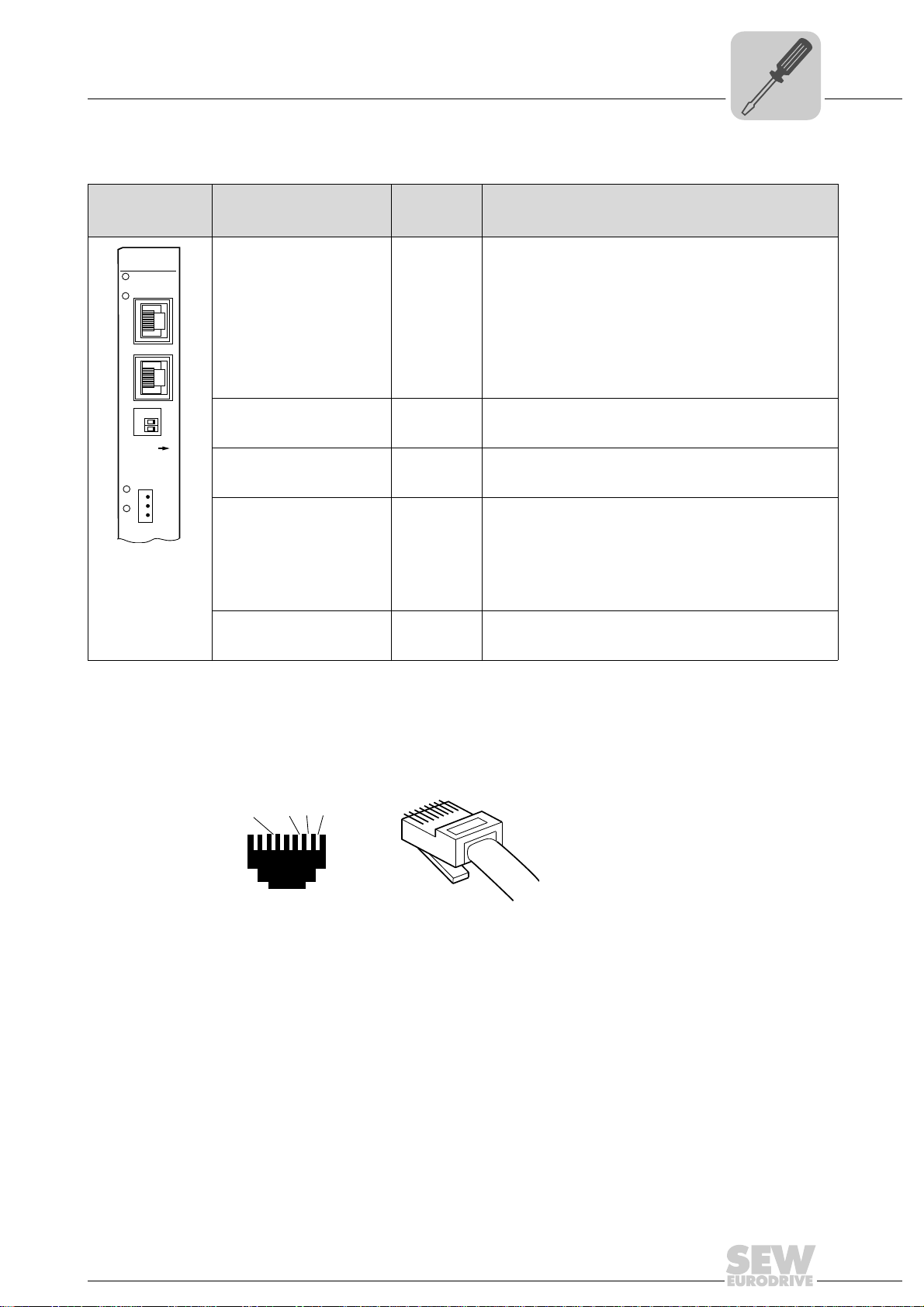
Front view
UFR41B fieldbus
gateway
65052AXX
Designation
LED
X30-1: Ethernet connection
LED Link (green)
LED Activity (yellow)
X30-2: Ethernet connection
LED Link (green)
LED Activity (yellow)
DIP switch 2
X38: CAN for safetyrelevant communication
LED
DIP switch
Function
Terminal
In EtherNet/IP and Modbus/TCP operation:
L14
L13
MODULE STATUS
NETWORK STATUS
In PROFINET operation:
L14
L13
L12
L11
0
= ON Resets the address parameters to their default values and
RUN
BUS FAULT
Reserved
Reserved
deactivates DHCP
• IP address: 192.168.10.4
• Subnet mask: 255.255.255.0
• Gateway: 192.168.10.4
1
= ON
2
1
= OFF
2
X38:1
X38:2
X38:3
EtherNet/IP and Modbus/TCP protocol is active
PROFINET protocol is active
Reserved
Reserved
Reserved
4.8 Pin assignment X30-1, X30-2 and X37
Use prefabricated, shielded RJ45 plug connectors compliant with IEC 11801 edition 2.0,
category 5.
54174AXX
A View from front B View from back
[1] Pin 1 TX+ Transmit Plus [2] Pin 2 TX- Transmit Minus
[3] Pin 3 RX+ Receive Plus [6] Pin 6 RX- Receive Minus
Manual – Fieldbus Gateway UFR41B EtherNet/IP, Modbus/TCP and PROFINET IO
25
4
Phone: 800.894.0412 - Fax: 888.723.4773 - Web: www.clrwtr.com - Email: info@clrwtr.com
Connecting UFR41B fieldbus gateway to Ethernet
Assembly and Installation Instructions
Shielding and routing bus cables
To connect UFR41B to the Ethernet, connect the Ethernet interface (X30-1, X30-2 or
X37) to the other network stations using a category 5, class D shielded twisted-pair
cable in accordance with IEC 11801 edition 2.0. The integrated switch provides support
for implementing a line topology using X30-1 and X30-2, and offers auto crossing
functions.
TIPS
• According to IEC 802.3, the maximum cable length for 10/100 MBaud Ethernet
(10BaseT / 100BaseT), e.g. between two network stations, is 100 m.
• We recommend that you do not directly connect non-SEW end devices to the
UFR41B option in order to minimize the load on the end devices in EtherNet/IP networks caused by undesired multicast data traffic. Connect non-SEW devices via a
network component that supports the IGMP snooping functionality (e.g. managed
switch).
Managed switches with IGMP snooping functionality is not required for PROFINET
IO and Modbus TCP networks.
4.9 Shielding and routing bus cables
Only use shielded cables and connection elements that meet the requirements of
category 5, class D according to IEC 11801 edition 2.0.
Correct shielding of the bus cable attenuates electrical interference that can occur in
industrial environments. The following measures ensure the best possible shielding:
• Manually tighten the mounting screws on the connectors, modules, and equipotential
bonding conductors.
• Use only connectors with a metal housing or a metallized housing.
• Connect the shielding in the connector over a wide surface area.
• Apply the shielding of the bus cable on both ends.
• Route signal and bus cables in separate cable ducts. Do not route them parallel to
power cables (motor leads).
• Use metallic, grounded cable racks in industrial environments.
• Route the signal cable and the corresponding equipotential bonding close to each
other using the shortest possible route.
• Avoid using plug connectors to extend bus cables.
• Route the bus cables closely along existing grounding surfaces.
CAUTION
In case of fluctuations in the ground potential, a compensating current may flow via the
bilaterally connected shield that is also connected to the protective earth (PE). Make
sure you supply adequate equipotential bonding according in accordance with relevant
VDE regulations in such a case.
26
Manual – Fieldbus Gateway UFR41B EtherNet/IP, Modbus/TCP and PROFINET IO
Assembly and Installation Instructions
Phone: 800.894.0412 - Fax: 888.723.4773 - Web: www.clrwtr.com - Email: info@clrwtr.com
The integrated Ethernet switch
4.10 The integrated Ethernet switch
You can use the integrated Ethernet switch to implement line topologies using X30-1
and X30-2 known from the fieldbus technology. Other bus topologies, such as star or
tree, are also possible. Ring topologies are not supported.
TIP
The number of Industrial Ethernet switches connected in line impacts on the telegram
runtime. If a telegram passes through the units, the telegram runtime is delayed by the
store & forward function of the Ethernet switch:
• for a telegram length of 64 bytes by approximately 10 µs (at 100 Mbit/s)
• for a telegram length of 1500 bytes by approximately 130 µs (at 100 Mbit/s)
This means that the more units a telegram has to pass through, the higher the telegram
runtime is.
Auto crossing The two ports leading out of the Ethernet switch have auto crossing functionality. This
means that they can use both patch and cross-over cables to connect to the next Ethernet station.
4
Auto negotiation The baud rate and the duplex mode is negotiated by both Ethernet nodes when
establishing the connection. For this purpose, both Ethernet ports of the EtherNet/IP
connection support an auto negotiation functionality and work with a baud rate of either
100 Mbit or 10 Mbit in full duplex or half-duplex mode.
Notes on multicast handling
• The integrated Ethernet switch does not provide a filter function for Ethernet multicast telegrams. Multicast telegrams that are usually sent in Ethernet/IP networks
from the adapters to the scanners (PLC) are passed on to all switch ports.
• IGMP snooping (managed switch) is not supported.
• SEW-EURODRIVE therefore recommends to connect the UFR41B option in EtherNet/IP networks only with network components that support IGMP snooping (e.g.
managed switch) or that have safety mechanisms integrated against excess multicast load (e.g. units from SEW-EURODRIVE). Units that do not have this integrated
function can fail due to high network loads. This restriction does not apply to
PROFINET IO or MODBUS TCP networks.
Manual – Fieldbus Gateway UFR41B EtherNet/IP, Modbus/TCP and PROFINET IO
27
4
UFR41B
2
2
0
1
ON
Phone: 800.894.0412 - Fax: 888.723.4773 - Web: www.clrwtr.com - Email: info@clrwtr.com
Assembly and Installation Instructions
Setting the DIP switches
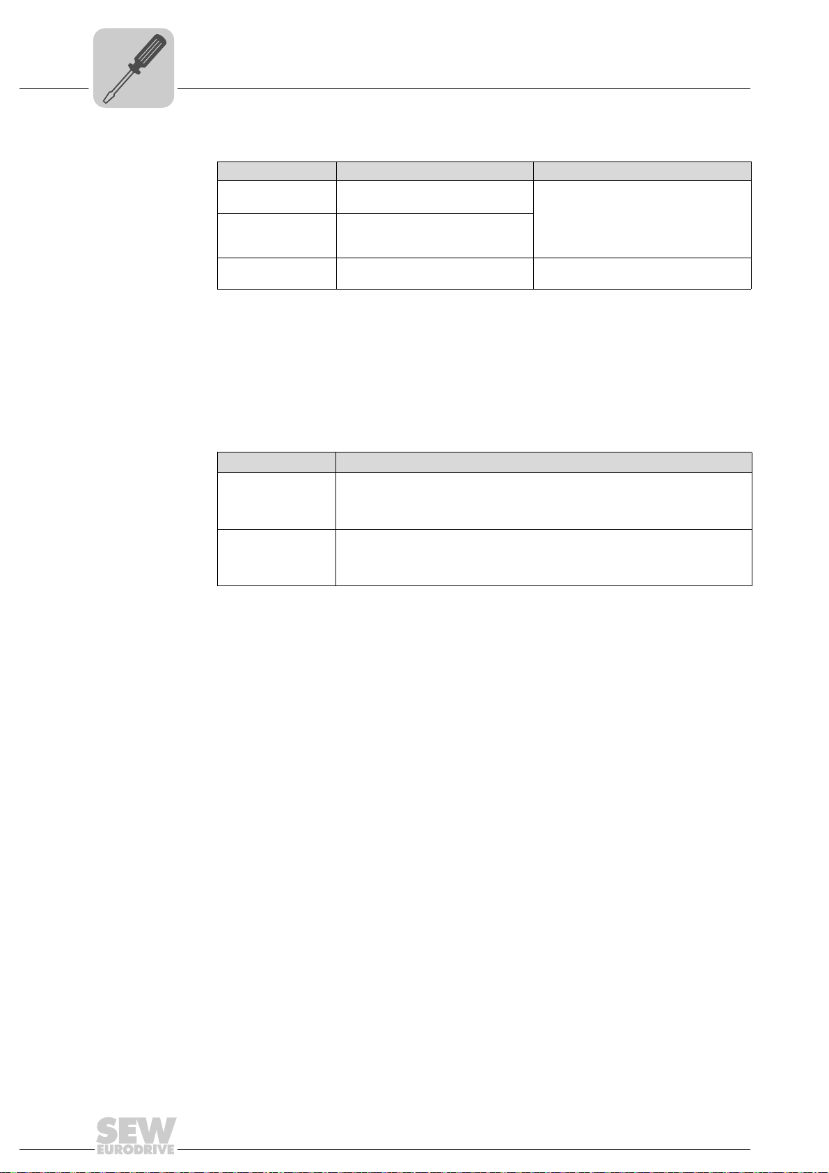
4.11 Setting the DIP switches
TIP
De-energize the UFR41B fieldbus gateway before you change a DIP switch setting.
The DIP switch settings are adopted during initialization only.
65053AXX
20 (Def IP) if the switch "2
are set when the DC 24 V backup voltage is switched on:
• IP address: 192.168.10.4
• Subnet mask: 255.255.255.0
• Default gateway: 192.168.10.4
• P785 DHCP / Startup configuration: Saved IP parameters (DHCP is deactivated)
1
2
(protocol) DIP switch "2
1
•2
= "1" (= right = ON): The EtherNet/IP and Modbus TCP/IP fieldbus protocol is
active.
1
•2
= "0" (= left = OFF): The PROFINET fieldbus protocol is active.
0
" is set to "1" (= right = ON), the following default IP address parameters
1
" is used to set the protocol that is used for communication.
28
Manual – Fieldbus Gateway UFR41B EtherNet/IP, Modbus/TCP and PROFINET IO
Assembly and Installation Instructions
Phone: 800.894.0412 - Fax: 888.723.4773 - Web: www.clrwtr.com - Email: info@clrwtr.com
Status LED of the UFR41B fieldbus gateway
4.12 Status LED of the UFR41B fieldbus gateway
The LEDs of the UFR41B fieldbus gateway indicate the current status of the UFR41B
option and the fieldbus system. The LEDs have a different meaning depending on the
set protocol.
UFR41B
L14
L13
4.12.1 Status LED in EtherNet/IP and Modbus/TCP operation
4
65054AXX
LED L13
(NETWORK
STATUS)
LED L14
(MODULE
STATUS)
Chapter 9 provides a summary of the status of the fieldbus interface corresponding to
the LED status.
The LED L13 (NETWORK STATUS) indicates the state of the fieldbus system.
States of the
NETWORK STA TUS
LED
Off The UFR41B option does not yet have any IP parameters.
Flashing green/red The UFR41B option card performs an LED test.
Flashing green There is no controlling IO connection.
Green There is a controlling EtherNet/IP or Modbus/TCP connection.
Red Conflict detected in the assigned IP addresses. Another station in the network uses
Flashing red The previously established controlling IO connection is in timeout status. The status
Meaning
the same IP address.
is reset by restarting communication.
LED L14 (MODULE STATUS) indicates that the bus electronics are operating correctly.
States of the
MODULE STATUS
LED
Off The UFR41B option card is either not supplied with voltage or it is faulty.
Flashing green • If the NETWORK STATUS LED is off at the same time, the TCP/IP stack of the
Flashing green/red The UFR41B option card performs an LED test.
Green The UFR41B option card is in normal operating state.
Red The UFR41B option card is in fault state.
Flashing red Conflict detected in the assigned IP addresses. Another station in the network uses
Meaning
UFR41B option card will be started. If this status continues and DHCP is
activated, the UFR41B option card waits for data from the DHCP server.
• If the NETWORK STATUS LED is flashing green at the same time, the
application of the UFR41B option card is started.
the same IP address.
Manual – Fieldbus Gateway UFR41B EtherNet/IP, Modbus/TCP and PROFINET IO
29
4
Phone: 800.894.0412 - Fax: 888.723.4773 - Web: www.clrwtr.com - Email: info@clrwtr.com
Assembly and Installation Instructions
Status LED of the UFR41B fieldbus gateway
4.12.2 Status LED in PROFINET operation
L13 LED (BUS
FAULT)
The LED L13 (BUS FAULT) indicates the status of the PROFINET.
Status of the
L13 LED
Off • PROFINET IO device is currently
Flashing green
Flashing
green/red
Red • Connection to the PROFINET IO
Yellow
Flashing yellow
Cause of error Remedy
exchanging data with the PROFINET
IO controller (data exchange).
• The flashing function in the
PROFINET IO controller configuration is activated to visually localize
the stations.
controller has failed.
• PROFINET IO device does not
detect a link
• Bus interruption
• PROFINET IO controller is not in
operation
• The STEP 7 hardware configuration
contains a module that is not
permitted.
-
-
• Check the PROFINET connection of
the UFR41B fieldbus gateway
• Check the PROFINET IO controller
• Check the cabling of your PROFINET
network
• Switch the STEP 7 hardware
configuration to ONLINE and analyze
the status of the components of the
slots in the PROFINET IO device.
LED L14 (RUN) LED L14 (RUN) indicates that the bus electronics are operating correctly.
Status of the
L14 LED
Green • UFR41B hardware OK.
Off • UFR41B is not ready for
Red • Error in the UFR41B hardware
Flashing
green
Flashing
yellow
Yellow • Switch the unit on again. Consult SEW service
Cause of error Remedy
• Functions properly
operation.
• Hardware of the UFR41B does
not boot up.
-
• Switch the unit on again. Consult SEW service
if the error occurs again.
• Switch the unit on again. Set default IP
address parameter using DIP switch "S1".
Consult SEW service if the error occurs again.
if the error occurs again.
30
Manual – Fieldbus Gateway UFR41B EtherNet/IP, Modbus/TCP and PROFINET IO
 Loading...