


 Loading...
Drive Technology \ Drive Automation \ System Integration \ Services
Assembly and Operating Instructions
Gear Units
R..7, F..7, K..7, K..9, S..7, SPIROPLAN® W
Edition 10/2013 |
20200544 / EN |

SEW-EURODRIVE—Driving the world

Contents
Contents
1 |
General Information ............................................................................................ |
5 |
|
|
1.1 |
How to use this documentation................................................................... |
5 |
|
1.2 |
Structure of the safety notes ....................................................................... |
5 |
|
1.3 |
Rights to claim under warranty ................................................................... |
6 |
|
1.4 |
Content of the documentation..................................................................... |
6 |
|
1.5 |
Exclusion of liability..................................................................................... |
6 |
|
1.6 |
Product names and trademarks.................................................................. |
6 |
|
1.7 |
Copyright..................................................................................................... |
6 |
2 |
Safety Notes ........................................................................................................ |
7 |
|
|
2.1 |
Preliminary information ............................................................................... |
7 |
|
2.2 |
General information .................................................................................... |
7 |
|
2.3 |
Target group ............................................................................................... |
8 |
|
2.4 |
Designated use ........................................................................................... |
8 |
|
2.5 |
Other applicable documentation ................................................................. |
8 |
|
2.6 |
Transport/storage........................................................................................ |
9 |
|
2.7 |
Setup........................................................................................................... |
9 |
|
2.8 |
Startup/operation ........................................................................................ |
9 |
|
2.9 |
Inspection/maintenance .............................................................................. |
9 |
3 |
Gear Unit Structure ........................................................................................... |
10 |
|
|
3.1 |
Basic structure of helical gear units .......................................................... |
10 |
|
3.2 |
Basic structure of parallel-shaft helical gear units..................................... |
11 |
|
3.3 |
Basic structure of helical-bevel gear units K..9 ......................................... |
12 |
|
3.4 |
Basic structure of helical-bevel gear units K..37 – K..187........................ |
13 |
|
3.5 |
Basic structure of helical-worm gear units ................................................ |
14 |
|
3.6 |
Basic structure of SPIROPLAN® gear units W..10 – W..30 ...................... |
15 |
|
3.7 |
Basic structure of SPIROPLAN® gear units W..37 – W..47 ...................... |
16 |
|
3.8 |
Nameplate/type designation ..................................................................... |
17 |
4 |
Mechanical Installation..................................................................................... |
18 |
|
|
4.1 |
Required tools/resources .......................................................................... |
18 |
|
4.2 |
Installation requirements........................................................................... |
19 |
|
4.3 |
Installing the gear unit............................................................................... |
20 |
|
4.4 |
Gear units with solid shaft......................................................................... |
27 |
|
4.5 |
Torque arms for shaft-mounted gear units................................................ |
29 |
|
4.6 |
Shaft-mounted gear units with keyway or splined hollow shaft................. |
32 |
|
4.7 |
Shaft-mounted gear units with shrink disk ................................................ |
39 |
|
4.8 |
Shaft-mounted gear units with TorqLOC® ................................................ |
43 |
|
4.9 |
Installing the protective cover ................................................................... |
55 |
|
4.10 |
Coupling of AM adapters .......................................................................... |
57 |
|
4.11 |
AQ. adapter coupling ................................................................................ |
61 |
|
4.12 |
EWH adapters........................................................................................... |
64 |
|
4.13 |
AD input shaft assembly ........................................................................... |
66 |
|
4.14 |
Accessory equipment................................................................................ |
71 |
Assembly and Operating Instructions – Gear Units R..7, F..7, K..7, K..9, S..7, SPIROPLAN® W |
|
|
3 |
|
|
|
|
|
|
|
|
|
|
|
|

Contents
5 |
Startup................................................................................................................ |
80 |
|
|
5.1 |
Checking the oil level ................................................................................ |
81 |
|
5.2 |
Pseudo-leakage at shaft seals.................................................................. |
81 |
|
5.3 |
Helical-worm and SPIROPLAN® W gear units ......................................... |
82 |
|
5.4 |
Helical/parallel-shaft helical/helical-bevel gear units................................. |
83 |
|
5.5 |
Gear units with backstop........................................................................... |
83 |
|
5.6 |
Components made of elastomers with fluorocarbon rubber ..................... |
84 |
6 |
Inspection/Maintenance ................................................................................... |
85 |
|
|
6.1 |
Preliminary work regarding gear unit inspection/maintenance ................. |
85 |
|
6.2 |
Inspection/maintenance intervals.............................................................. |
86 |
|
6.3 |
Lubricant change intervals ........................................................................ |
87 |
|
6.4 |
Inspection/maintenance for the AL / AM / AQ. / EWH adapter ................. |
88 |
|
6.5 |
Inspection/maintenance for the AD input shaft assembly ......................... |
88 |
|
6.6 |
Inspection/maintenance for the gear unit.................................................. |
89 |
7 Mounting Positions......................................................................................... |
104 |
|
7.1 |
Designation of the mounting positions .................................................... |
104 |
7.2 |
Churning losses ...................................................................................... |
105 |
7.3 |
Mounting position MX ............................................................................. |
105 |
7.4 |
Universal mounting position M0.............................................................. |
105 |
7.5 |
Mounting positions of SPIROPLAN® gear units...................................... |
106 |
7.6 |
Key.......................................................................................................... |
106 |
7.7 |
Helical gearmotors R .............................................................................. |
107 |
7.8 |
Helical gearmotors RX ............................................................................ |
110 |
7.9 |
Parallel-shaft helical gearmotors F ......................................................... |
112 |
7.10 |
Helical-bevel gearmotors K..................................................................... |
115 |
7.11 |
Helical-worm gearmotors S..................................................................... |
123 |
7.12 |
SPIROPLAN® W gearmotors.................................................................. |
129 |
8 |
Technical Data................................................................................................. |
135 |
|
|
8.1 |
Extended storage ................................................................................... |
135 |
|
8.2 |
Lubricants ............................................................................................... |
136 |
9 |
Malfunctions .................................................................................................... |
145 |
|
|
9.1 |
Gear units ............................................................................................... |
145 |
|
9.2 |
Adapters AM / AQ. / AL / EWH ............................................................... |
146 |
|
9.3 |
AD input shaft assembly ......................................................................... |
147 |
|
9.4 |
Customer service ................................................................................... |
147 |
|
9.5 |
Disposal .................................................................................................. |
147 |
10 |
Address list...................................................................................................... |
148 |
|
|
Index |
................................................................................................................. |
160 |
4 |
|
|
Assembly and Operating Instructions – Gear Units R..7, F..7, K..7, K..9, S..7, SPIROPLAN® W |
|
|
|
|
|
|
|
|
|
|
|
|
General Information |
1 |
|
How to use this documentation |
||
|
1 General Information
1.1How to use this documentation
The documentation is an integral part of the product and contains important information on operation and service. The documentation is written for all employees who assemble, install, start up, and service this product.
The documentation must be accessible and legible. Make sure that persons responsible for the system and its operation, as well as persons who work independently on the unit, have read through the documentation carefully and understood it. If you are unclear about any of the information in this documentation, or if you require further information, contact SEW-EURODRIVE.
1.2Structure of the safety notes
1.2.1Meaning of signal words
The following table shows the graduation and meaning of the signal words for safety notes, warnings regarding potential risks of damage to property, and other notes.
Signal word |
Meaning |
Consequences if disregarded |
DANGER! |
Imminent hazard |
Severe or fatal injuries |
|
|
|
WARNING! |
Possible dangerous situation |
Severe or fatal injuries |
|
|
|
CAUTION! |
Possible dangerous situation |
Minor injuries |
|
|
|
NOTICE |
Possible damage to property |
Damage to the drive system or its envi- |
|
|
ronment |
NOTE |
Useful information or tip: Simpli- |
|
|
fies handling of the drive sys- |
|
|
tem. |
|
|
|
|
1.2.2Design of the section-related safety notes
Section-related safety notes do not apply to a specific action, but to several actions pertaining to one subject. The symbols used either indicate a general hazard or a specific hazard.
This is the formal structure of a safety note for a specific section:
SIGNAL WORD!
Type and source of danger.
Possible consequence(s) if disregarded.
•Measure(s) to prevent the danger.
1.2.3Design of the embedded safety notes
Embedded safety notes are directly integrated into the instructions just before the description of the dangerous action.
This is the formal structure of an embedded safety note:
• SIGNAL WORD! Type and source of hazard. Possible consequence(s) if disregarded.
– Measure(s) to prevent the hazard.
Assembly and Operating Instructions – Gear Units R..7, F..7, K..7, K..9, S..7, SPIROPLAN® W |
|
|
5 |
|
|
|
|
|
|
|
|
|
|
|
|

1 |
General Information |
|
Rights to claim under warranty |
||
|
1.3Rights to claim under warranty
A requirement of fault-free operation and fulfillment of any rights to claim under limited warranty is that you adhere to the information in the documentation. Therefore read the documentation before you start working with the unit.
1.4Content of the documentation
This document contains additional safety-related information and conditions for operation in safety-related applications.
1.5Exclusion of liability
You must comply with the information contained in this documentation to ensure safe operation and to achieve the specified product characteristics and performance features. SEW-EURODRIVE assumes no liability for injury to persons or damage to equipment or property resulting from non-observance of these operating instructions. In such cases, any liability for defects is excluded.
1.6Product names and trademarks
All product names in this documentation are trademarks or registered trademarks of their respective titleholders.
1.7Copyright
© 2013 – SEW-EURODRIVE. All rights reserved.
Unauthorized reproduction, modification, distribution or any other use of the whole or any part of this documentation is strictly prohibited.
6 |
|
|
Assembly and Operating Instructions – Gear Units R..7, F..7, K..7, K..9, S..7, SPIROPLAN® W |
|
|
|
|
|
|
|
|
|
|
|
|

Safety Notes |
2 |
|
Preliminary information |
||
|
2 Safety Notes
The following basic safety notes must be read carefully to prevent injury to persons and damage to property. The operator must ensure that the basic safety notes are read and adhered to. Make sure that persons responsible for the system and its operation, as well as persons who work independently on the unit, have read through the operating instructions carefully and understood them. If you are unclear about any of the information in this documentation or if you require further information, please contact SEWEURODRIVE.
2.1Preliminary information
The following safety notes are primarily concerned with the use of the following components: Gear unit series R..7, F..7, K..7, K..9, S..7, SPIROPLAN® W. If you are using gearmotors, you must also observe the safety notes for motors in the corresponding operating instructions.
Also observe the supplementary safety notes in the individual sections of this documentation.
2.2General information
WARNING
Danger of fatal injury or risk of injury during the operation of motors or gearmotors caused by live, bare (in the event of open connectors/terminal boxes) and movable or rotating parts.
Risk of burns caused by hot surfaces Severe or fatal injuries
•All work related to transport, storage, installation, assembly, connection, startup, maintenance and repair may only be carried out by qualified personnel.
•For transport, storage, installation, assembly, connection, startup, maintenance and repair it is important that you adhere to the information in the following documents:
–Warning and safety signs on the motor/gearmotor
–All the project planning documents, startup instructions and wiring diagrams related to the drive
–System-specific regulations and requirements
–National/regional regulations governing the safety and prevention of accidents
•Never install damaged products.
•Never operate or energize the unit without the necessary protection covers or housing.
•Use the unit only for its intended purpose.
•Make sure the unit is installed and operated properly.
INFORMATION
In the event of damage caused by transport, submit a complaint to the shipping company immediately.
This documentation provides additional information.
Assembly and Operating Instructions – Gear Units R..7, F..7, K..7, K..9, S..7, SPIROPLAN® W |
|
|
7 |
|
|
|
|
|
|
|
|
|
|
|
|

2 |
Safety Notes |
|
Target group |
||
|
2.3Target group
Any mechanical work may only be performed by adequately qualified personnel. Qualified personnel in the context of this documentation are persons familiar with the design, mechanical installation, troubleshooting and servicing of the product who possess the following qualifications:
•Training in mechanical engineering, e.g. as a mechanic or mechatronics technician (final examinations must have been passed).
•They are familiar with these operating instructions.
Any electronic work may only be performed by adequately qualified electricians. Qualified electricians in the context of this documentation are persons familiar with electrical installation, startup, troubleshooting and servicing of the product who possess the following qualifications:
•Training in electrical engineering, e.g. as an electrician, electronics or mechatronics technician (final examinations must have been passed).
•They are familiar with these operating instructions.
All work in further areas of transportation, storage, operation and waste disposal must only be carried out by persons who are trained appropriately.
All qualified personnel must wear appropriate protective clothing.
2.4Designated use
The gear unit series R..7, F..7, K..7, K..9, S..7, SPIROPLAN® W is intended for use in industrial systems.
The gear units may only be used according to the specifications in the technical documentation from SEW-EURODRIVE as well as the specifications on the nameplate. They fulfill the applicable standards and regulations.
When installed in machines, startup (i.e. start of designated operation) is prohibited until it is determined that the machine complies with the local laws and directives. In the individual area of application, you must especially observe the Machinery Directive 2006/42/EC as well as the EMC Directive 2004/108/EC. The EMC test specifications EN 61000-4-2, EN 61000-4-3, EN 61000-4-4, EN 61000-4-6 and EN 61000-6-2 form the basis for this.
Use in potentially explosive atmospheres is prohibited unless specifically designated otherwise.
2.5Other applicable documentation
The following publications and documents have to be observed as well:
•"DR.71 – 225, 315 AC Motors" operating instructions for gearmotors
•Operating instructions of any attached options
•"Gear Units" catalog or
•"Gearmotors" catalog
8 |
|
|
Assembly and Operating Instructions – Gear Units R..7, F..7, K..7, K..9, S..7, SPIROPLAN® W |
|
|
|
|
|
|
|
|
|
|
|
|
Safety Notes |
2 |
|
Transport/storage |
||
|
2.6Transport/storage
Inspect the shipment for any damage that may have occurred in transit as soon as you receive the delivery. Inform the shipping company immediately in the event of damage. It may be necessary to preclude startup.
Tighten the eyebolts securely. They are designed to carry only the weight of the motor/gearmotor; do not attach any additional loads.
The built-in lifting eyebolts comply with DIN 580. Always observe the loads and regulations listed in this standard. If the gearmotor is equipped with two eyebolts, then both should be used for transportation. In this case, the tension force vector of the slings must not exceed a 45° angle according to DIN 580.
Use suitable, sufficiently rated handling equipment if required. Reattach these in the case of further transportation.
Store the motor/gearmotor in a dry, dust-free environment if it is not to be installed straight away. You must not store the motor/gearmotor outdoors or on the fan guard. The motor/gearmotor can be stored for up to 9 months without requiring any special measures before startup.
2.7Setup
NOTICE
Danger due to static overdetermination if gear units with foot (e.g. KA19/29B, KA127/157B or FA127/157B) are mounted both via the torque arm and via the foot plate.
Risk of injuries and damage to property.
•Especially with the KA.9B/T variant, it is not permitted to use the foot plates and the torque arm at the same time.
•The KA.9B/T variant may only be mounted via torque arms.
•K.9 or KA.9B variants may only be mounted via the foot plate.
•If you want to use foot plates and torque arms for mounting, consult with SEW-EU- RODRIVE.
Observe the notes in the "Mechanical Installation" section.
2.8Startup/operation
Check the oil level before startup as described in chapter Inspection/Maintenance (page 85).
Check that the direction of rotation is correct in decoupled status. Listen out for unusual grinding noises as the shaft rotates.
Secure keys for test mode without output elements. Do not deactivate monitoring and protection equipment even in test mode.
Switch off the gearmotor if in doubt whenever changes occur in relation to normal operation (e.g. increased temperature, noise, vibration). Determine the cause and contact SEW-EURODRIVE, if required.
2.9Inspection/maintenance
Observe the notes in chapter "Inspection/Maintenance".
Assembly and Operating Instructions – Gear Units R..7, F..7, K..7, K..9, S..7, SPIROPLAN® W |
|
|
9 |
|
|
|
|
|
|
|
|
|
|
|
|

3 |
Gear Unit Structure |
|
Basic structure of helical gear units |
||
|
3 Gear Unit Structure
INFORMATION
The following figures are block diagrams. Their purpose is only to make it easier to assign components to the spare parts lists. Discrepancies may occur depending on the gear unit size and version.
3.1Basic structure of helical gear units
|
|
|
|
|
|
|
[59] |
|
|
|
|
|
|
|
[20] |
|
|
|
|
|
|
|
[24] |
|
|
|
|
[515] |
[101] |
|
|
|
|
|
|
[516] |
|
|
|
|
|
|
|
[517] |
[100] |
|
|
|
|
|
|
|
[47] |
[1] |
|
|
|
|
[2] |
|
[102] |
||
|
|
|
[45] |
|
|
||
|
|
|
|
|
|
||
|
|
|
|
|
[59] |
|
|
|
|
|
[43] |
|
|
|
|
|
[181] |
|
|
|
|
|
|
|
[42] |
[3] |
|
|
|
|
|
|
[41] |
|
[6] |
[25] [88] |
|
||
|
|
|
|
|
[22] |
||
|
|
|
|
|
|
|
|
|
|
|
|
[11] |
[17] |
|
|
|
|
|
[12] |
|
|
|
|
|
|
[19] |
[9] |
|
|
|
|
|
|
|
|
|
[521] |
|
|
|
|
|
|
|
|
|
|
|
|
|
|
|
|
[522] |
|
[8] |
[7] |
|
|
|
|
[523] |
|
|
|
|
|
|
|
|
[59] |
|
|
|
|
[31] |
|
[32] |
[30] |
|
|
|
|
|
|
|
|

 [34] [4] [5]
[506] [37]
[39][507]
[131][508]
19194251
[1] |
Pinion |
[19] |
Key |
[42] |
Rolling bearing |
[507] |
Shim |
[2] |
Gear |
[20] |
Breather valve |
[43] |
Key |
[508] |
Shim |
[3] |
Pinion shaft |
[22] |
Gear unit housing |
[45] |
Rolling bearing |
[515] |
Shim |
[4] |
Gear |
[24] |
Eyebolt |
[47] |
Retaining ring |
[516] |
Shim |
[5] |
Pinion shaft |
[25] |
Rolling bearing |
[59] |
Screw plug |
[517] |
Shim |
[6] |
Gear |
[30] |
Rolling bearing |
[88] |
Retaining ring |
[521] |
Shim |
[7] |
Output shaft |
[31] |
Key |
[100] |
Inspection cover |
[522] |
Shim |
[8] |
Key |
[32] |
Spacer tube |
[101] |
Hex head screw |
[523] |
Shim |
[9] |
Oil seal |
[34] |
Rolling bearing |
[102] |
Gasket |
|
|
[11] |
Rolling bearing bearing |
[37] |
Rolling bearing |
[131] |
Closing cap |
|
|
[12] |
Retaining ring |
[39] |
Retaining ring |
[181] |
Closing cap |
|
|
[17] |
Spacer tube |
[41] |
Retaining ring |
[506] |
Shim |
|
|
10 |
|
|
Assembly and Operating Instructions – Gear Units R..7, F..7, K..7, K..9, S..7, SPIROPLAN® W |
|
|
|
|
|
|
|
|
|
|
|
|
Gear Unit Structure |
3 |
|
Basic structure of parallel-shaft helical gear units |
||
|
3.2Basic structure of parallel-shaft helical gear units
|
[515] |
|
[2] |
[45] |
|
|
[20] |
|
|
[43] |
|
|
[22] |
[59] |
|
|
[516] |
|
|
|
[1] |
||
|
[517] |
[42] |
[3] |
|
|
|
|
[41] |
|
|
|
|
|||
[181] |
|
|
|
[4] |
[30] |
|
[161] |
|
|
|
|
|
|||
|
|
|
|
|
|
||
|
|
|
|
[32] |
|
[59] |
|
|
|
|
[31] |
|
|
|
|
|
|
|
|
|
|
|
|
|
[506] |
|
[5] |
|
|
|
|
|
[39] |
[37] |
|
|
|
|
|
[131] |
[507] |
|
|
[183] |
[165 |
||
[508] |
|
|
|
|
|
|
|
|
|
|
[19] |
|
|
|
[160] |
|
|
|
|
|
|
|
|
|
|
|
|
|
|
[88] |
[102] |
|
|
|
|
|
[94] |
[100] |
|
|
|
|
|
|
[521] |
||
|
|
|
|
[92] |
[25] |
||
|
|
|
|
[93] |
[522] |
[101] |
|
|
|
|
|
[91] |
|
[523] |
|
[7]
|
|
|
|
|
|
[59] |
|
|
|
[17] |
[6] |
|
|
|
|
|
[9] |
[11] |
|
|
|
|
|
|
|
|
|
|
|
||
|
[81] |
|
|
|
|
|
|
[14] |
|
|
|
|
|
|
|
|
[16] |
|
|
|
|
|
|
|
|
|
|
|
|
|
19298059 |
[1] |
Pinion |
[22] |
Gear unit housing |
[91] |
Retaining ring |
[506] |
Shim |
[2] |
Gear |
[25] |
Rolling bearing |
[92] |
Washer |
[507] |
Shim |
[3] |
Pinion shaft |
[30] |
Rolling bearing |
[93] |
Lock washer |
[508] |
Shim |
[4] |
Gear |
[31] |
Key |
[94] |
Hex head screw |
[515] |
Shim |
[5] |
Pinion shaft |
[32] |
Spacer tube |
[100] |
Inspection cover |
[516] |
Shim |
[6] |
Gear |
[37] |
Rolling bearing |
[101] |
Hex head screw |
[517] |
Shim |
[7] |
Hollow shaft |
[39] |
Retaining ring |
[102] |
Gasket |
[521] |
Shim |
[9] |
Oil seal |
[41] |
Retaining ring |
[131] |
Closing cap |
[522] |
Shim |
[11] |
Rolling bearing bearing |
[42] |
Rolling bearing |
[160] |
Closing plug |
[523] |
Shim |
[14] |
Hex head screw |
[43] |
Key |
[161] |
Closing cap |
|
|
[16] |
Output flange |
[45] |
Rolling bearing |
[165] |
Closing plug |
|
|
[17] |
Spacer tube |
[59] |
Screw plug |
[181] |
Closing cap |
|
|
[19] |
Key |
[81] |
Shield ring |
[183] |
Oil seal |
|
|
[20] |
Breather valve |
[88] |
Retaining ring |
|
|
|
|
Assembly and Operating Instructions – Gear Units R..7, F..7, K..7, K..9, S..7, SPIROPLAN® W |
|
|
11 |
|
|
|
|
|
|
|
|
|
|
|
|

3 |
Gear Unit Structure |
|
Basic structure of helical-bevel gear units K..9 |
||
|
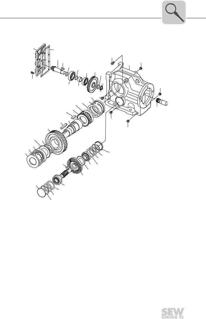
3.3Basic structure of helical-bevel gear units K..9
[521][89]
[522][88]
|
[523] |
[106] [6] |
[25] |
[20] |
|
|
[59] |
|
|
|
[167] |
|
|
|
[22] |
|
|
|
[159] |
|
|
|
[59] |
|
|
[7] |
[19] |
|
[8] |
[43] |
||
|
|||
|
|
|
[36] |
[17] |
[5] |
|
|
|
[11] |
[183] |
[48] |
[536] |
|
|
|
|
[518] |
|
[80] |
|
[537] |
[141] |
|
|
[12] |
[519] |
|
|
|
[538] |
|
|
|
[9] |
[520] |
[7] |
|
|
|
|
[45] |
|
|
|
|
|
|
|
[42] |
[2] [530] |
|
|
|
|
|
|
|
|
[531] |
|
|
|
|
|
|
|
|
[532] |
[115] |
[163] [26]
[44]
[29] [150]
[1]
[24]
7421610507
[1] |
Pinion |
[24] |
Eyebolt |
[80] |
Key |
[520] |
Shim |
[2] |
Gear |
[25] Deep groove ball bearing |
[88] |
Retaining ring |
[521] |
Shim |
|
[5] |
Pinion shaft |
[26] |
Housing stage 1 |
[89] |
Closing cap |
[522] |
Shim |
[6] |
Gear |
[29] |
Gasket |
[106] |
Stud |
[523] |
Shim |
[7] |
Output shaft |
[36] |
Stud |
[115] |
Retaining ring |
[530] |
Shim |
[8] |
Key |
[42] |
Tapered roller bearing |
[141] |
Bushing |
[531] |
Shim |
[9] |
Oil seal |
[43] |
Key |
[150] |
Hex nut |
[532] |
Shim |
[11] |
Deep groove ball bearing |
[44] |
Gasket |
[159] |
Closing plug |
[536] |
Shim |
[12] |
Retaining ring |
[45] |
Tapered roller bearing |
[163] |
Supporting ring |
[537] |
Shim |
[17] |
Spacer tube |
[48] Supporting ring (only K..29) |
[167] |
Closing plug |
[538] |
Shim |
|
[19] |
Key |
[59] |
Screw plug |
[183] |
Oil seal |
|
|
[20] |
Breather valve |
[62] |
Screw plug |
[518] |
Shim |
|
|
[22] |
Gear unit housing |
[63] |
Thread reduction |
[519] |
Shim |
|
|
12 |
|
|
Assembly and Operating Instructions – Gear Units R..7, F..7, K..7, K..9, S..7, SPIROPLAN® W |
|
|
|
|
|
|
|
|
|
|
|
|
Gear Unit Structure |
3 |
|
Basic structure of helical-bevel gear units K..37 – K..187 |
||
|
3.4Basic structure of helical-bevel gear units K..37 – K..187
[100] |
[102] |
|
|
|
|
|
|
|
|
|
|
|
|
|
|
|
[3] |
[536] |
|
|
|
|
[20] |
|
[533] |
|
|
[59] |
|||
|
[43] [537] |
|
|
||||
|
|
[538] |
[534] |
|
|
[22] |
|
|
|
|
[535] |
|
[2] |
||
|
|
|
|
[45] |
|||
|
|
|
|
|
[114] |
||
|
|
|
|
|
|
|
|
[101] |
|
|
|
|
|
|
[113] |
|
|
|
|
|
|
|
|
|
|
[42] |
[119] |
|
|
[59] |
|
|
|
|
|
[523] |
[89] |
[116] |
|
|
|
|
|
[59] |
|||
|
|
|
|
[522] |
|
|
|
|
|
[25] |
[521][88] |
|
|
||
|
|
|
|
|
|
||
|
|
[84] |
|
|
|
|
[1] |
|
|
[19] |
|
|
|
|
|
|
[8] |
[7] |
|
|
|
|
[59] |
|
[6] |
|
|
|
|
|
[59] |
|
|
|
|
|
|
|
|
[83] |
[17] |
|
|
|
|
|
|
[11] |
|
|
|
|
|
|
|
[12] |
|
|
|
|
|
|
|
[9] |
|
|
|
|
|
|
[132][161] |
|
|
|
|
|
|
|
|
|
[31] |
|
|
|
|
[133] |
|
|
|
|
[30] |
[542] |
|||
|
|
|
|
|
|||
|
|
|
|
[135] |
|
[543] |
|
|
|
|
|
|
[544] |
||
|
|
|
|
|
|
|
|
 [4] [5]
|
[131] |
|
[37] |
|
|
|
|
|
|
|
|
|
|
|
|
|
|
|
[506] |
|
|
|
|
|
|
|
[507] |
|
|
|
|
|
|
[137] |
[508] |
|
|
|
|
|
|
[39] |
|
|
|
|
|
|
|
|
|
|
|
|
19301131 |
[1] |
Pinion |
[25] |
Rolling bearing |
[102] |
Gasket |
[522] |
Shim |
[2] |
Gear |
[30] |
Rolling bearing |
[113] |
Slotted nut |
[523] |
Shim |
[3] |
Pinion shaft |
[31] |
Key |
[114] |
Lock washer |
[533] |
Shim |
[4] |
Gear |
[37] |
Rolling bearing |
[116] |
Threadlocker |
[534] |
Shim |
[5] |
Pinion shaft |
[39] |
Retaining ring |
[119] |
Spacer tube |
[535] |
Shim |
[6] |
Gear |
[42] |
Rolling bearing |
[131] |
Closing cap |
[536] |
Shim |
[7] |
Output shaft |
[43] |
Key |
[132] |
Retaining ring |
[537] |
Shim |
[8] |
Key |
[45] |
Rolling bearing |
[133] |
Supporting ring |
[538] |
Shim |
[9] |
Oil seal |
[59] |
Screw plug |
[135] |
Shield ring |
[542] |
Shim |
[11] |
Rolling bearing bearing |
[83] |
Shield ring |
[161] |
Closing cap |
[543] |
Shim |
[12] |
Retaining ring |
[84] |
Shield ring |
[506] |
Shim |
[544] |
Shim |
[17] |
Spacer tube |
[88] |
Retaining ring |
[507] |
Shim |
|
|
[19] |
Key |
[89] |
Closing cap |
[508] |
Shim |
|
|
[20] |
Breather valve |
[100] |
Inspection cover |
[521] |
Shim |
|
|
[22] |
Gear unit housing |
[101] |
Hex head screw |
[521] |
Shim |
|
|
Assembly and Operating Instructions – Gear Units R..7, F..7, K..7, K..9, S..7, SPIROPLAN® W |
|
|
13 |
|
|
|
|
|
|
|
|
|
|
|
|

3 |
Gear Unit Structure |
|
Basic structure of helical-worm gear units |
||
|
3.5Basic structure of helical-worm gear units
|
|
|
|
|
[101] |
[59] |
[20] |
|
|
[506] |
|
|
|
|
[100] |
[131] |
[39] |
[507] |
|
|
|
|
|
[137] |
|
|
[102] |
|
|
||
|
|
[37] |
|
|
|
[22] |
|
|
|
[5] |
|
|
|
|
|
|
|
[43] |
[30] |
[2] [61] [59] |
|
|
|
|
|
|
|
|
[1]
[19]
[89]
[59]
[523] [88] [25] [522][521]
[7]
[6]
[520][11]
[12][519]
[9][518]
19304203
[1] |
Pinion |
[20] |
Breather valve |
[88] |
Retaining ring |
[518] |
Shim |
[2] |
Gear |
[22] |
Gear unit housing |
[89] |
Closing cap |
[519] |
Shim |
[5] |
Worm gear |
[25] |
Rolling bearing |
[100] |
Inspection cover |
[520] |
Shim |
[6] |
Worm gear |
[30] |
Rolling bearing |
[101] |
Hex head screw |
[521] |
Shim |
[7] |
Output shaft |
[37] |
Rolling bearing |
[102] |
Gasket |
[522] |
Shim |
[9] |
Oil seal |
[39] |
Retaining ring |
[131] |
Closing cap |
[523] |
Shim |
[11] |
Rolling bearing bearing |
[43] |
Key |
[137] |
Supporting ring |
|
|
[12] |
Retaining ring |
[59] |
Screw plug |
[506] |
Shim |
|
|
[19] |
Key |
[61] |
Retaining ring |
[507] |
Shim |
|
|
14 |
|
|
Assembly and Operating Instructions – Gear Units R..7, F..7, K..7, K..9, S..7, SPIROPLAN® W |
|
|
|
|
|
|
|
|
|
|
|
|

Gear Unit Structure |
3 |
Basic structure of SPIROPLAN® gear units W..10 – W..30 |
3.6Basic structure of SPIROPLAN® gear units W..10 – W..30
[100]

 [101]
[101]
|
[65] |
|
|
[102] |
[66] |
[68] |
|
[71] |
[143] |
||
|
|
[72] |
|
|
|
|
[1] |
[22] |
|
|
|
|
[89] |
|
|
|
[88] |
|
|
|
[521] |
|
|
|
[522] |
|
|
|
[25] [523] |
|
|
|
[6] |
|
|
[19] |
[250] |
|
|
[251]


 [17] [8]


[7]
 [11]
[11]
 [518] [519] [12] [520]
 [9]
[9]
|
|
|
|
|
|
|
19307275 |
[1] |
Pinion |
[19] |
Key |
[88] |
Retaining ring |
[518] |
Shim |
[6] |
Gear |
[22] |
Gear unit housing |
[89] |
Closing cap |
[519] |
Shim |
[7] |
Output shaft |
[25] |
Rolling bearing |
[100] |
Inspection cover |
[520] |
Shim |
[8] |
Key |
[65] |
Oil seal |
[101] |
Hex head screw |
[521] |
Shim |
[9] |
Oil seal |
[66] |
Rolling bearing bearing |
[102] |
Gasket |
[522] |
Shim |
[11] |
Rolling bearing bearing |
[68] |
Retaining ring |
[143] |
Supporting ring |
[523] |
Shim |
[12] |
Retaining ring |
[71] |
Supporting ring |
[250] |
Retaining ring |
|
|
[17] |
Spacer tube |
[72] |
Retaining ring |
[251] |
Retaining ring |
|
|
Assembly and Operating Instructions – Gear Units R..7, F..7, K..7, K..9, S..7, SPIROPLAN® W |
|
|
15 |
|
|
|
|
|
|
|
|
|
|
|
|

3 |
Gear Unit Structure |
Basic structure of SPIROPLAN® gear units W..37 – W..47 |
3.7Basic structure of SPIROPLAN® gear units W..37 – W..47
[521][89]
[523][88]
|
|
|
|
[6] |
[25] |
|
|
|
|
|
[22] |
|
|
|
|
|
|
|
[19] |
|
|
|
|
|
|
|
|
[7] |
|
|
|
|
|
|
|
|
[8] |
|
|
|
|
|
|
|
[518] |
|
|
|
|
|
[59] |
[5] |
|
[11] |
|
|
|
|
|
|
[33] |
|
[519] |
|
|
|
|
|
|
|
|
[12][520] |
[59] |
|
|
|
|
|
|
[32] |
[9] |
[44] |
[133] |
|
|
|
[1] |
|
|
|
|
|
|
|
|
|||
|
|
|
|
[37] |
|
|
|
|
|
|
|
[506] |
|
|
|
|
|
|
|
|
|
|
|
|
|
|
|
|
|
|
|
[5] |
[31] |
|
|
|
|
|
|
|
|
|
|
|
|
|
|
|
|
|
[30] |
|
|
|
|
|
|
|
|
|
[137] |
|
|
|
|
|
|
|
|
[2] |
|
|
|
|
|
|
|
|
[61] |
|
|
|
|
|
|
|
|
[26] |
[36] |
|
|
|
|
|
|
|
9007199860613387 |
[1] |
Pinion |
[22] |
Gear unit housing |
[59] |
Screw plug |
[521] |
Shim |
[2] |
Gear |
[25] Deep groove ball bearing |
[61] |
Retaining ring |
[522] |
Shim |
|
[5] |
Pinion shaft |
[26] |
Housing stage 1 |
[88] |
Retaining ring |
[523] |
Shim |
[6] |
Gear |
[30] Deep groove ball bearing |
[89] |
Closing cap |
|
|
|
[7] |
Output shaft |
[31] |
Key |
[133] |
Shim |
|
|
[8] |
Key |
[32] |
Spacer tube |
[137] |
Shim |
|
|
[9] |
Oil seal |
[33] |
Retaining ring |
[506] |
Shim |
|
|
[11] |
Deep groove ball bearing |
[36] |
Hex head screw |
[518] |
Shim |
|
|
[12] |
Retaining ring |
[37] Deep groove ball bearing |
[519] |
Shim |
|
|
|
[19] |
Key |
[44] |
O-ring |
[520] |
Shim |
|
|
16 |
|
|
Assembly and Operating Instructions – Gear Units R..7, F..7, K..7, K..9, S..7, SPIROPLAN® W |
|
|
|
|
|
|
|
|
|
|
|
|
Gear Unit Structure |
3 |
|
Nameplate/type designation |
||
|
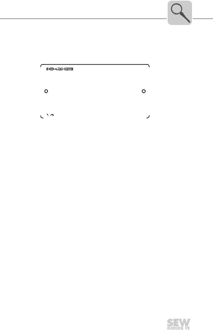
3.8Nameplate/type designation
3.8.1Nameplate
The following figure shows an example of a nameplate for a helical-bevel gear unit with input cover:
|
|
|
|
|
|
|
|
|
|
|
|
|
|
|
|
|
|
|
|
|
|
|
|
|
76646 Bruchsal |
|
|
|
|
|
|
|
|
||||||||||||||
|
K87 AD4 |
|
|
|
|
|
|
|
|
||||||||||||||
|
|
|
|
|
|
|
|
|
|
|
|
|
|
|
|
|
|
|
|
IM |
M1A |
|
|
|
na |
r/min |
1400/20 |
|
i |
70,46 |
|
|
|||||||||||||||
|
|
|
|
Mamax Nm |
2700 |
Memax |
Nm 41 |
kg 105 |
|
||||||||||||||
|
|
|
|
|
|
|
|
|
|
|
|
|
|
|
|
|
|
|
|
Made in Germany |
|
||
|
|
|
|
|
|
|
|
|
|
|
CLP HC 220 Synth. Öl / 3,71l |
|
|
06415911 |
|
|
|||||||
|
|
|
|
|
|
|
|
|
|
|
|||||||||||||
|
|
|
|
|
|
|
|
|
|
|
|||||||||||||
|
|
|
|
|
|
|
|
|
|
|
|
|
|
|
|
|
|
|
|
|
4472018699 |
||
na |
[r/min] |
|
|
Maximum permitted output speed |
|
|
|
||||||||||||||||
Mamax |
[Nm] |
|
|
Maximum permitted output torque |
|
|
|
||||||||||||||||
Memax |
[Nm] |
|
|
Maximum permitted input torque |
|
|
|
||||||||||||||||
i |
|
|
|
|
|
|
|
|
|
|
|
Gear unit ratio |
|
|
|
|
|||||||
IM |
|
|
|
|
|
|
|
|
|
|
|
Mounting position |
|
|
|
|
|||||||
3.8.2Type designation
Helical-bevel gear |
A helical-bevel gear unit with AQ adapter has, for example, the following type designa- |
||||||||
units |
tion: |
|
|
|
|
|
|
|
|
|
K |
37 /R AQA 80 /1 |
|||||||
|
|
|
|
|
|
|
|
|
Variants |
|
|
|
|
|
|
|
|
|
|
|
|
|
|
|
|
|
|
|
|
|
|
|
|
|
|
|
|
|
Flange classification |
|
|
|
|
|
|
|
|
|
|
|
|
|
|
|
|
|
|
|
Adapter designation: e.g. for servomotors |
|
|
|
|
|
|
|
|
|
- AQA: Adapter with keyway |
|
|
|
|
|
|
|
|
|
- AQH: Adapter with clamping ring hub |
|
|
|
|
|
|
|
|
|
Option: e.g. for servo gear units .../ R: |
|
|
|
|
|
|
|
|
|
Reduced circumferential backlash |
|
|
|
|
|
|
|
|
|
Gear unit size: e.g. B. 37 |
|
|
|
|
|
|
|
|
|
|
|
|
|
|
|
|
|
|
|
Gear unit type: e.g. K |
|
|
|
|
|
|
|
|
|
|
Assembly and Operating Instructions – Gear Units R..7, F..7, K..7, K..9, S..7, SPIROPLAN® W |
|
|
17 |
|
|
|
|
|
|
|
|
|
|
|
|

4
18
Mechanical Installation
Required tools/resources
4 Mechanical Installation
4.1Required tools/resources
•Set of wrenches
•If necessary, torque wrench for:
–Shrink disks
–Motor adapter AQH Or EWH
–Input shaft assembly with centering shoulder
•Mounting device
•Compensation elements (shims, spacing rings)
•Fasteners for input and output elements
•Lubricant (e.g. NOCO® Fluid)
•Bolt locking compound (for input shaft assembly with centering shoulder), e.g. Loctite® 243
Standard parts are not included in the delivery
4.1.1Installation tolerances
Shaft end |
Flanges |
||
Diameter tolerance in accordance with DIN 748 |
Centering shoulder tolerance to DIN 42948 |
||
• |
ISO k6 for solid shafts with Ø ≤ 50 mm |
• |
ISO j6 for b1 ≤ 230 mm |
• |
ISO m6 for solid shafts with Ø > 50 mm |
• |
ISO h6 with b1 > 230 mm |
•ISO H7 for hollow shafts
•Center bore in accordance with DIN 332, shape DR
Assembly and Operating Instructions – Gear Units R..7, F..7, K..7, K..9, S..7, SPIROPLAN® W

Mechanical Installation |
4 |
|
Installation requirements |
||
|
4.2Installation requirements
CAUTION
Risk of injury due to protruding gear unit parts.
Minor injuries.
•Keep a sufficient safety distance to the gear unit/gearmotor.
NOTICE
Damage to the gear unit/gearmotor due to improper installation.
Possible damage to property
•Strictly adhere to the notes in this chapter.
Make sure that the following requirements are met before you start installing the unit:
•The drive has not been damaged during transportation or storage.
•The entries on the nameplate of the gearmotor match the voltage supply system.
•When the unit is installed in abrasive ambient conditions, protect the output end oil seals against wear.
•The output shafts and flange surfaces must be completely free from anti-corrosion agents, contamination or similar. Use a commercially available solvent for cleaning. Do not expose the sealing lips of the oil seals to the solvent – damage to the material.
•For standard drives:
–Ambient temperature according to the technical documentation, nameplate and lubricant table in section "Lubricants".
–No harmful oils, acids, gases, vapors, radiation etc. in the vicinity
•For special designs:
–The drive is designed in accordance with the ambient conditions. Observe the information on the nameplate.
•For helical-worm/SPIROPLAN® W gear units:
–No large external mass moments of inertia which could exert a retrodriving load on the gear unit.
–Self-locking with η’ (retrodriving) < 0.5; Calculation : η’ = 2 – 1/η
•For servomotor mounting:
–Do not assemble the drive without having ensured that there will be sufficient ventilation after installation to prevent heat build-up.
Assembly and Operating Instructions – Gear Units R..7, F..7, K..7, K..9, S..7, SPIROPLAN® W |
|
|
19 |
|
|
|
|
|
|
|
|
|
|
|
|

4 |
Mechanical Installation |
|
Installing the gear unit |
||
|
4.3Installing the gear unit
NOTICE
Danger due to static overdetermination if gear units with foot (e.g. KA19/29B, KA127/157B or FA127/157B) are mounted both via the torque arm and via the foot plate.
Risk of injuries and damage to property.
•Especially with the KA.9B/T variant, it is not permitted to use the foot plates and the torque arm at the same time.
•The KA.9B/T variant may only be mounted via torque arms.
•K.9 or KA.9B variants may only be mounted via the foot plate.
•If you want to use foot plates and torque arms for mounting, consult with SEWEURODRIVE.
CAUTION
Improper installation may result in damage to the gear unit or gearmotor.
Possible damage to property.
•Protect the gear unit from direct cold air currents. Condensation may cause water to accumulate in the oil.
•It is important that you observe the notes in this chapter.
CAUTION
Risk of trapping and crushing due to improper disassembly of heavy components.
Risk of injury.
•Remove the shrink disk properly.
•Work on the gear unit only when the machine is at a standstill. Secure the drive unit against unintentional power-up.
The gear unit or gearmotor is only allowed to be installed in the specified mounting position. Observe the information on the nameplate. SPIROPLAN® gear units of size W10 – W30 are mounting position-independent.
The support structure must have the following features:
•Level
•Vibration damping
•Torsionally rigid
The following table shows the maximally permitted flatness defect for footand flangemounting (guide values based on DIN ISO 1101):
• Gear unit size ≤ 67: |
Max. 0.4 mm |
|
• |
Gear unit size 77 – 107: |
Max. 0.5 mm |
• |
Gear unit size 137 – 147: |
Max. 0.7 mm |
•Gear unit size 157 – 187: Max. 0.8 mm
Do not tighten the housing legs and mounting flanges against one another and ensure that you comply with the permitted overhung and axial loads. Observe chapter "Project Planning" in the Gear unit/gearmotor catalog for calculating the permitted overhung and axial loads.
20 |
|
|
Assembly and Operating Instructions – Gear Units R..7, F..7, K..7, K..9, S..7, SPIROPLAN® W |
|
|
|
|
|
|
|
|
|
|
|
|
Mechanical Installation |
4 |
|
Installing the gear unit |
||
|
Secure gearmotors using quality 8.8 screws.
Secure the following gearmotors using quality 10.9 screws:
•RF37, R37F with flange Ø = 120 mm
•RF37, RF47, R47F with flange Ø = 140 mm
•RF57, R57F with flange Ø = 160 mm
•FF, FAF, KF, KAF with flange Ø 250 mm
•and RZ37, RZ47, RZ57, RZ67, RZ77, RZ87
INFORMATION
When installing the gear unit, make sure that the oil level and drain plugs as well as the breather plugs are easily accessible!
At the same time, also check that the oil fill corresponds to the specifications for the intended mounting position (see chapter "Lubricant fill quantities (page 139)" or refer to the information on the nameplate). The gear units are filled with the required oil volume at the factory. There may be slight deviations at the oil level plug as a result of the mounting position, which are permitted within the manufacturing tolerances.
Adjust the lubricant fill volumes and the position of the breather valve accordingly in the event of a change of mounting position. Observe chapter "Lubricant fill quantities" and chapter "Mounting Positions".
Consult the SEW customer service if you intend to change the mounting position of K gear to M5 or M6 or between M5 and M6.
Please contact our SEW customer service if you want to change the mounting position of size S47 – S97 helical-worm gear units to mounting position M2 or M3.
Use plastic inserts (2 – 3 mm thick) if there is a risk of electrochemical corrosion between the gear unit and the driven machine. The material used must have an electrical leakage resistance < 109 Ω. Electrochemical corrosion can occur between various metals, for example, cast iron and high-grade steel. Also fit the bolts with plastic washers. Ground the housing additionally – use the grounding bolts on the motor.
Assembly and Operating Instructions – Gear Units R..7, F..7, K..7, K..9, S..7, SPIROPLAN® W |
|
|
21 |
|
|
|
|
|
|
|
|
|
|
|
|

4
22
Mechanical Installation
Installing the gear unit
4.3.1Tightening torques for retaining screws
Mount the gearmotors with the following tightening torques:
|
Tightening torque screw / nut |
Bolt/nut |
Strength class 8.8 |
|
[Nm] |
M6 |
11 |
M8 |
25 |
M10 |
48 |
M12 |
86 |
M16 |
210 |
M20 |
410 |
M24 |
710 |
M30 |
1450 |
M36 |
2500 |
M42 |
4600 |
M48 |
6950 |
M56 |
11100 |
Mount the specified gearmotors in flange-mounted design with the following increased tightening torques:
|
|
Bolt/nut |
Tightening torque screw / nut |
|
Flange |
Gear unit |
Strength class 10.9 |
||
|
||||
|
|
|
[Nm] |
|
120 |
RF37 |
M6 |
14 |
|
140 |
RF37, RF47 |
M8 |
35 |
|
160 |
RF57 |
M8 |
35 |
|
60ZR |
RZ37 |
M8 |
35 |
|
70ZR |
RZ47 |
M8 |
35 |
|
80ZR |
RZ57 |
M10 |
69 |
|
95ZR |
RZ67 |
M10 |
69 |
|
110ZR |
RZ77 |
M12 |
120 |
|
130ZR |
RZ87 |
M12 |
120 |
|
250 |
FF77, KF77, |
M12 |
120 |
|
FAF77, KAF77 |
||||
|
|
|
Assembly and Operating Instructions – Gear Units R..7, F..7, K..7, K..9, S..7, SPIROPLAN® W

Mechanical Installation |
4 |
|
Installing the gear unit |
||
|
4.3.2Gear unit mounting
INFORMATION
For gear units in foot/flange-mounted design in connection with VARIBLOC® variablespeed gear units, use quality 10.9 bolts and suitable washers for connecting the customer flange.
To improve the friction contact between flange and mounting surface, SEWEURODRIVE recommends anaerobic gaskets or an anaerobic glue.
Foot-mounted gear The following table shows the thread sizes of the foot-mounted gear units depending on units the gear unit type and size:
|
|
|
Gear unit type |
|
|
|
Screw |
R / R..F |
RX |
F / |
K / KH..B / |
S |
W |
|
|
|
FH..B / FA..B |
KV..B / KA..B |
|
|
M6 |
07 |
|
|
19 |
|
10/20 |
|
|
|
|
|
|
|
M8 |
17/27/37 |
|
27/37 |
29 |
37 |
30/37/47 |
|
|
|
|
|
|
|
M10 |
|
57 |
47 |
37/47 |
47/57 |
|
|
|
|
|
|
|
|
M12 |
47/57/67 |
67 |
57/67 |
57/67 |
67 |
|
|
|
|
|
|
|
|
M16 |
77/87 |
77/87 |
77/87 |
77 |
77 |
|
|
|
|
|
|
|
|
M20 |
97 |
97/107 |
97 |
87 |
87 |
|
|
|
|
|
|
|
|
M24 |
107 |
|
107 |
97 |
97 |
|
|
|
|
|
|
|
|
M30 |
137 |
|
127 |
107/167 |
|
|
|
|
|
|
|
|
|
M36 |
147/167 |
|
157 |
127/157/187 |
|
|
|
|
|
|
|
|
|
Gear units with B14 flange design and/or hollow shaft
The following table shows the thread sizes of the gear units with B14 flange and/or hollow shaft depending on the gear unit type and size:
|
|
|
Gear unit type |
|
|
Screw |
RZ |
FAZ / FHZ |
KAZ / |
SA / |
WA |
|
|
|
KHZ / KVZ |
SAZ / SHZ |
|
M6 |
07/17/27 |
|
|
37 |
10/20/301) |
M8 |
37/47 |
27/37/47 |
37/47 |
47/57 |
37 |
|
|
|
|
|
|
M10 |
57/67 |
|
|
|
47 |
|
|
|
|
|
|
M12 |
77/87 |
57/67/77 |
57/67/77 |
67/77 |
|
|
|
|
|
|
|
M16 |
|
87/97 |
87/97 |
87/97 |
|
|
|
|
|
|
|
M20 |
|
107/127 |
107/127 |
|
|
|
|
|
|
|
|
M24 |
|
157 |
157 |
|
|
|
|
|
|
|
|
1)For W30 gear units mounted directly to a CMP motor or mounted via an EWH.. adapter, the thread size is M8.
Assembly and Operating Instructions – Gear Units R..7, F..7, K..7, K..9, S..7, SPIROPLAN® W |
|
|
23 |
|
|
|
|
|
|
|
|
|
|
|
|

4 |
Mechanical Installation |
|
Installing the gear unit |
||
|
Gear units with B5 |
The following table shows the thread sizes of the gear units with B5 flange depending |
|||||||
flange |
on the gear unit type, size and flange diameter: |
|
|
|
|
|||
|
|
|
|
|
|
|
|
|
|
|
|
|
|
Gear unit type |
|
|
|
|
Flange Ø |
Screw |
RF / |
FF / |
|
KF / KAF / |
SF / |
WF / WAF |
|
[mm] |
|
R..F / RM |
FAF / FHF |
|
KHF / KVF |
SAF /SHF |
|
|
80 |
M6 |
|
|
|
|
|
10 |
|
110 |
M8 |
|
|
|
|
|
20 |
|
120 |
M6 |
07/17/27 |
|
|
19 |
37 |
10/20/30/37 |
|
140 |
M8 |
07/17/27/37/47 |
|
|
|
|
|
|
160 |
M8 |
07/17/27/37/47 |
27/37 |
|
19/29/37 |
37/47 |
30/37/47 |
|
200 |
M10 |
37/47/57/67 |
47 |
|
29/47 |
57/67 |
|
|
250 |
M12 |
57/67/77/87 |
57/67 |
|
57/67 |
77 |
|
|
300 |
M12 |
67/77/87 |
77 |
|
77 |
|
|
|
350 |
M16 |
77/87/97/107 |
87 |
|
87 |
87 |
|
|
450 |
M16 |
97/107/137/147 |
97/107 |
|
97/107 |
97 |
|
|
550 |
M16 |
107/137/147/167 |
127 |
|
127 |
|
|
|
660 |
M20 |
147/167 |
157 |
|
157 |
|
|
24 |
|
|
Assembly and Operating Instructions – Gear Units R..7, F..7, K..7, K..9, S..7, SPIROPLAN® W |
|
|
|
|
|
|
|
|
|
|
|
|

Mechanical Installation
Installing the gear unit
4.3.3Installation in damp locations or outdoors
Drives are supplied in corrosion-resistant versions with a surface protection coating for use in damp areas or outdoors. Repair any damage to the paint work (e.g. on the breather valve or the eyebolts).
When mounting the motors onto AM, AQ adapters and to AR, AT start-up and friction couplings, seal the flange areas with a suitable sealing compound, e.g. Loctite® 574.
Units installed outdoors must be protected from the sun. Suitable protective devices are required, such as covers or roofs. Avoid any heat accumulation. The operator must ensure that foreign objects do not impair the function of the gear unit (e.g. falling objects or coverings).
4.3.4Gear unit venting
The following gear units do not require venting:
•R..07 in mounting positions M1, M2, M3, M5 and M6
•R..17, R..27 and F..27 in mounting positions M1, M3, M5 and M6
•SPIROPLAN® W..10, W..20, W..30 gear units
•SPIROPLAN® W..37, W..47 gear units in mounting positions M1, M2, M3, M5 and M6
•K..19, K..29 gear units in mounting positions M1, M2, M3, M5 and M6
SEW-EURODRIVE supplies all other gear units with the breather valve installed and activated according to the particular mounting position.
Exceptions:
1.SEW supplies the following gear units with a screw plug on the vent hole provided:
–Gear units with pivoted mounting positions, if possible
–Gear units for inclined mounting
The breather valve is located in the motor terminal box. Before startup, replace the highest screw plug with the breather valve provided.
2.SEW supplies a breather valve in a plastic bag for mount-on gear units requiring venting on the input side.
3.Enclosed gear units are supplied without a breather valve.
4.In some countries, the breather valve is installed, but not activated due to possible pressure fluctuations during transport. In these cases, the breather valve must be activated by removing the transport protection as described in chapter "Activating the breather valve".
Assembly and Operating Instructions – Gear Units R..7, F..7, K..7, K..9, S..7, SPIROPLAN® W
4
25
4 |
Mechanical Installation |
|
Installing the gear unit |
||
|
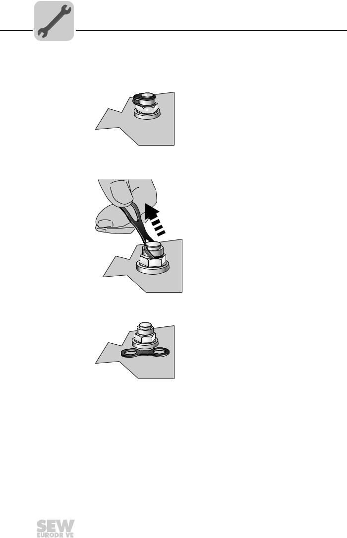
Activating the |
Check whether the breather valve is activated. If the breather valve has not been acti- |
|
breather valve |
vated, you must remove the transportation protection device from the breather valve be- |
|
|
fore starting up the gear unit. |
|
|
1. Breather valve with transportation protection device |
|
|
|
|
|
|
|
|
|
|
|
|
|
|
|
|
|
|
|
|
|
|
|
|
|
|
|
|
211319051
2. Remove transport fixture
211316875
3. Activated breather valve
211314699
26 |
|
|
Assembly and Operating Instructions – Gear Units R..7, F..7, K..7, K..9, S..7, SPIROPLAN® W |
|
|
|
|
|
|
|
|
|
|
|
|

Mechanical Installation |
4 |
|
Gear units with solid shaft |
||
|
4.3.5Painting the gear unit
NOTICE
Breather valves and oil seals may be damaged during painting or re-painting.
Possible damage to property.
•Thoroughly cover the breather valves and the sealing lip of the oil seals with strips prior to painting.
•Remove the strips after painting.
4.4Gear units with solid shaft
4.4.1Notes on installation
INFORMATION
Mounting is easier if you first apply lubricant to the output element or heat it up briefly (to 80 - 100 °C).
4.4.2Assembling input and output elements
NOTICE
Bearing, hosing or shaft may be damaged due to improper assembly. Possible damage to property
• Assemble the input and output components only using a mounting device. Use the center bore and the thread on the shaft end for positioning.
• Never force belt pulleys, couplings, pinions, etc. onto the shaft end by hitting them with a hammer.
|
• In the case of belt pulleys, make sure the belt is tensioned correctly in accordance |
|||||||||||||||||||
|
|
with the manufacturer's instructions. |
||||||||||||||||||
|
• Power transmission elements should be balanced after fitting and must not give |
|||||||||||||||||||
|
|
rise to any impermissible radial or axial forces (see the "Gearmotors" or "Explosion- |
||||||||||||||||||
|
|
Proof Drives" catalog for permitted values). |
||||||||||||||||||
Using a mounting |
The following figure shows a mounting device for installing couplings or hubs on gear |
|||||||||||||||||||
device |
unit or motor shaft ends. Should you be able to tighten the screw without any problems, |
|||||||||||||||||||
|
you may not need the thrust bearing on the mounting device. |
|||||||||||||||||||
|
[1] |
[2] |
|
|
||||||||||||||||
|
|
|
|
|
|
|
|
|
|
|
|
|
|
|
|
|
|
|
|
|
|
|
|
|
|
|
|
|
|
|
|
|
|
|
|
|
|
|
|
|
|
|
|
|
|
|
|
|
|
|
|
|
|
|
|
|
|
|
|
|
|
|
|
|
|
|
|
|
|
|
|
|
|
|
|
|
|
|
|
|
|
|
|
|
|
|
|
|
|
|
|
|
|
|
|
|
|
|
|
|
|
|
|
|
|
|
|
|
|
|
|
|
|
|
|
|
|
|
|
|
|
|
|
|
|
|
|
|
|
|
|
|
|
|
|
|
|
|
|
|
|
|
|
|
|
|
|
|
|
|
|
|
|
|
|
|
|
|
|
|
|
|
|
|
|
|
|
|
|
|
|
|
|
|
|
|
|
|
|
|
|
|
|
|
|
|
|
|
[3]
211368587
[1]Gear unit shaft end
[2]Thrust bearing
[3]Coupling hub
Assembly and Operating Instructions – Gear Units R..7, F..7, K..7, K..9, S..7, SPIROPLAN® W |
|
|
27 |
|
|
|
|
|
|
|
|
|
|
|
|
4 |
Mechanical Installation |
|
Gear units with solid shaft |
||
|
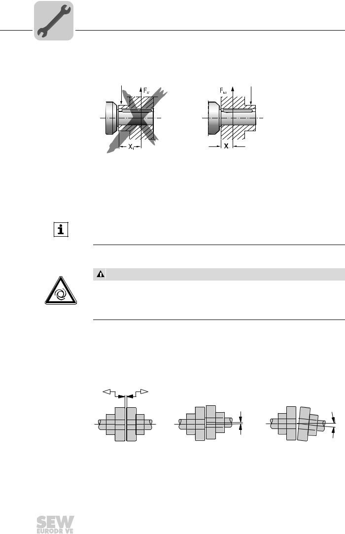
Avoiding excessive overhung loads
Avoid high overhung loads by installing the gear or chain sprocket according to figure B if possible.
[1] |
[A] |
[1] Hub
[A]Unfavorable
[B]Correct
[1] |
[B]
211364235
INFORMATION
Mounting is easier if you first apply lubricant to the output element or heat it up briefly (to 80 - 100 °C).
4.4.3Mounting of couplings
CAUTION
Risk of injury due to moving drive elements, such as belt pulleys or couplings, during operation.
Risk of jamming and crushing.
•Cover input and output components with a touch guard.
Adjust the following misalignments according to the coupling manufacturer's specifications when mounting couplings:
a)Maximum and minimum clearance
b)Axial offset
c)Angular offset
a) |
b) |
c) |
211395595
28 |
|
|
Assembly and Operating Instructions – Gear Units R..7, F..7, K..7, K..9, S..7, SPIROPLAN® W |
|
|
|
|
|
|
|
|
|
|
|
|

Mechanical Installation |
4 |
|
Torque arms for shaft-mounted gear units |
||
|
4.5Torque arms for shaft-mounted gear units
NOTICE
Improper mounting may result in damage to the gear unit.
Possible damage to property.
•Do not place torque arms under strain when mounting.
•Use screws of quality 8.8 to fasten torque arms.
4.5.1Parallel-shaft helical gear units
The following figure shows the torque arm for parallel-shaft helical gear units.
|
[3] |
c |
|
a |
|
[1] |
|
|
|
|
|
[2] |
|
<![if ! IE]> <![endif]>ød |
|
|
<![if ! IE]> <![endif]>+0.5 |
|
|
<![if ! IE]> <![endif]>øb |
9007199466107403
[1]Screw
[2]Washer
[3]Nut
Proceed as follows to mount the rubber buffers:
1.Use screws [1] and washers according to the following table.
2.Use two nuts to secure the screw connection [3].
3.Tighten the screw until the initial stress "∆ L" of the buffers is reached according to the table.
|
|
Rubber buffer |
|
|
|
Gear unit |
Diameter |
Inner |
Length |
Washer width |
∆ L (taut) |
|
|
diameter |
(loose) |
|
|
|
d [mm] |
b [mm] |
c [mm] |
a [mm] |
[mm] |
F..27 /G |
40 |
12.5 |
20 |
5 |
1 |
|
|
|
|
|
|
F..37 /G |
40 |
12.5 |
20 |
5 |
1 |
|
|
|
|
|
|
F..47 /G |
40 |
12.5 |
20 |
5 |
1.5 |
|
|
|
|
|
|
F..57 /G |
40 |
12.5 |
20 |
5 |
1.5 |
|
|
|
|
|
|
F..67 /G |
40 |
12.5 |
20 |
5 |
1.5 |
|
|
|
|
|
|
F..77 /G |
60 |
21.0 |
30 |
10 |
1.5 |
|
|
|
|
|
|
F..87 /G |
60 |
21.0 |
30 |
10 |
1.5 |
|
|
|
|
|
|
F..97 /G |
80 |
25.0 |
40 |
12 |
2 |
|
|
|
|
|
|
F..107 /G |
80 |
25.0 |
40 |
12 |
2 |
|
|
|
|
|
|
F..127 /G |
100 |
32.0 |
60 |
15 |
3 |
|
|
|
|
|
|
F..157 /G |
120 |
32.0 |
60 |
15 |
3 |
|
|
|
|
|
|
Assembly and Operating Instructions – Gear Units R..7, F..7, K..7, K..9, S..7, SPIROPLAN® W |
|
|
29 |
|
|
|
|
|
|
|
|
|
|
|
|

4 |
Mechanical Installation |
|
Torque arms for shaft-mounted gear units |
||
|
4.5.2Helical-bevel gear units K..19 – 29
The following figure shows the torque arm for helical-bevel gear units KA19 – 29.
•Apply bearings to both sides of the bushing [1].
•Mount connection side B so that it mirrors A.
45°
[1] |
7717631499
Gear unit |
Screws |
Tightening torque |
K..19 /T |
4 x M8 × 22 – 8.8 |
25 Nm |
K..29 /T |
4 x M8 × 22 – 8.8 |
25 Nm |
4.5.3Helical-bevel gear units K..37 – 157
The following figure shows the toque arm for helical-bevel gear units.
•Apply bearings to both sides of the bushing [1].
•Mount connection side B so that it mirrors A.
[1] |
211362059
Gear unit |
Screws |
Tightening torque |
K..37 /T |
4 × M10 × 25 – 8.8 |
48 Nm |
K..47 /T |
4 × M10 × 30 – 8.8 |
48 Nm |
K..67 /T |
4 × M12 × 35 – 8.8 |
86 Nm |
K..77 /T |
4 × M16 × 40 – 8.8 |
210 Nm |
K..87 /T |
4 × M16 × 45 – 8.8 |
210 Nm |
K..97 /T |
4 × M20 × 50 – 8.8 |
410 Nm |
K..107 /T |
4 × M24 × 60 – 8.8 |
710 Nm |
K..127 /T |
4 × M36 × 130 – 8.8 |
2.500 Nm |
K..157 /T |
4 × M36 × 130 – 8.8 |
2.500 Nm |
30 |
|
|
Assembly and Operating Instructions – Gear Units R..7, F..7, K..7, K..9, S..7, SPIROPLAN® W |
|
|
|
|
|
|
|
|
|
|
|
|
Loading...