


Drive Technology \ Drive Automation \ System Integration \ Services
Manual
MOVITRAC® MC07B
Functional Safety
Edition 12/2011 |
19396414 / EN |

SEW-EURODRIVE—Driving the world

Contents
Contents
1 |
General Information ............................................................................................ |
4 |
|
|
1.1 |
How to use this documentation................................................................... |
4 |
|
1.2 |
Underlying standards .................................................................................. |
4 |
|
1.3 |
Structure of the safety notes ....................................................................... |
5 |
|
1.4 |
Rights to claim under warranty ................................................................... |
6 |
|
1.5 |
Exclusion of liability..................................................................................... |
6 |
|
1.6 |
Copyright notice .......................................................................................... |
6 |
|
1.7 |
Document content....................................................................................... |
6 |
|
1.8 |
Other applicable publications...................................................................... |
6 |
2 |
Integrated Safety Technology............................................................................ |
7 |
|
|
2.1 |
Safe condition ............................................................................................. |
7 |
|
2.2 |
Safety concept ............................................................................................ |
7 |
|
2.3 |
Schematic representation – "safety concept for MOVITRAC® B"............... |
8 |
|
2.4 |
Safety functions .......................................................................................... |
9 |
|
2.5 |
Restrictions ............................................................................................... |
11 |
3 |
Safety Conditions.............................................................................................. |
12 |
|
|
3.1 |
Approved devices ..................................................................................... |
13 |
|
3.2 |
Installation requirements........................................................................... |
14 |
|
3.3 |
Requirements on the external safety controller ........................................ |
16 |
|
3.4 |
Requirements on startup........................................................................... |
17 |
|
3.5 |
Requirements on operation....................................................................... |
17 |
4 |
Connection Variants ......................................................................................... |
18 |
|
|
4.1 |
General information .................................................................................. |
18 |
|
4.2 |
Requirements............................................................................................ |
19 |
|
4.3 |
Disconnection of a single drive ................................................................. |
20 |
|
4.4 |
Disconnection of group drives................................................................... |
26 |
5 |
Technical Data .................................................................................................. |
30 |
|
|
5.1 |
Safety characteristics................................................................................ |
30 |
|
5.2 |
Electronics data X17: Signal terminal block for STO safety contact ......... |
30 |
|
Index |
................................................................................................................... |
31 |
Phone: 800.894.0412 - Fax: 888.723.4773 - Web: www.clrwtr.com - Email: info@clrwtr.com
Manual – Functional Safety MOVITRAC® MC07B |
|
|
3 |
|
|
|
|
|
|
|
|
|
|
|
|
1 |
General Information |
|
How to use this documentation |
||
|
1 General Information
1.1How to use this documentation
The documentation is an integral part of the product and contains important information on operation and service. The documentation is written for all employees who assemble, install, start up, and service this product.
The documentation must be accessible and legible. Make sure that persons responsible for the system and its operation, as well as persons who work independently on the unit, have read through the documentation carefully and understood it. If you are unclear about any of the information in this documentation, or if you require further information, contact SEW-EURODRIVE.
Make sure you always use the latest documentation and software version.
Our documentation is available in various languages for download from the SEW homepage. Consult SEW-EURODRIVE if you are unclear
about any of the information in this documentation, or if you require further information. You can also order the printed documentation from SEW-EURODRIVE.
1.2Underlying standards
The safety assessment of the unit is based on the following standards and safety classes:
Underlying standards
• Performance level (PL) according to EN ISO 13849Safety class/underlying standard 1:2008
• Category 3 according to EN 954-1:1996
Phone: 800.894.0412 - Fax: 888.723.4773 - Web: www.clrwtr.com - Email: info@clrwtr.com
4 |
|
|
Manual – Functional Safety MOVITRAC® MC07B |
|
|
|
|
|
|
|
|
|
|
|
|

General Information |
1 |
|
Structure of the safety notes |
||
|
1.3Structure of the safety notes
1.3.1Meaning of signal words
The following table shows the grading and meaning of the signal words for safety notes, notes on potential risks of damage to property, and other notes.
Signal word |
Meaning |
Consequences if disregarded |
DANGER |
Imminent danger |
Severe or fatal injuries |
|
|
|
WARNING |
Possible dangerous situation |
Severe or fatal injuries |
|
|
|
CAUTION |
Possible dangerous situation |
Minor injuries |
|
|
|
NOTICE |
Possible damage to property |
Damage to the drive system or its |
|
|
environment |
INFORMATION |
Useful information or tip: |
|
|
implifies the handling of the |
|
|
drive system. |
|
|
|
|
1.3.2Structure of the section safety notes
Section safety notes do not apply to a specific action but to several actions pertaining to one subject. The symbols used either indicate a general hazard or a specific hazard.
This is the formal structure of a section safety note:
SIGNAL WORD
Type and source of danger.
Possible consequence(s) if disregarded.
•Measure(s) to prevent the danger.
1.3.3Structure of the embedded safety notes
Embedded safety notes are directly integrated in the instructions just before the description of the dangerous action.
This is the formal structure of an embedded safety note:
• SIGNAL WORD Type and source of danger. Possible consequence(s) if disregarded.
– Measure(s) to prevent the danger.
Phone: 800.894.0412 - Fax: 888.723.4773 - Web: www.clrwtr.com - Email: info@clrwtr.com
Manual – Functional Safety MOVITRAC® MC07B |
|
|
5 |
|
|
|
|
|
|
|
|
|
|
|
|

1 |
General Information |
|
Rights to claim under warranty |
||
|
1.4Rights to claim under warranty
A requirement of fault-free operation and fulfillment of any rights to claim under limited warranty is that you adhere to the information in the MOVITRAC® documentation. Therefore, read the operating instructions before you start working with the unit.
Make sure that the documentation is available to persons responsible for the system and its operation as well as to persons who work independently on the unit. You must also ensure that the documentation is legible.
1.5Exclusion of liability
Adherence to the operating instructions is essential to ensure safe operation of MOVITRAC® MC07B units and to achieve the specified product characteristics and performance features. SEW-EURODRIVE assumes no liability for injury to persons or damage to equipment or property resulting from non-adherence to these operating instructions. In such cases, any liability for defects is excluded.
1.6Copyright notice
©2010 – SEW-EURODRIVE. All rights reserved.
Copyright law prohibits the unauthorized duplication, modification, distribution, and use of this document, in whole or in part.
1.7Document content
This publication contains conditions and amendments related to MOVITRAC® MC07B units in safety-related applications.
The system comprises a drive inverter with AC motor and safety-tested external disconnecting device.
1.8Other applicable publications
This document supplements the MOVITRAC® MC07B operating instructions and limits the application notes according to the following information. It may only be used together with the MOVITRAC® MC07B operating instructions.
Phone: 800.894.0412 - Fax: 888.723.4773 - Web: www.clrwtr.com - Email: info@clrwtr.com
6 |
|
|
Manual – Functional Safety MOVITRAC® MC07B |
|
|
|
|
|
|
|
|
|
|
|
|

Integrated Safety Technology |
2 |
|
Safe condition |
||
|
2 Integrated Safety Technology
The safety technology of MOVITRAC® MC07B units described below has been developed and tested in accordance with the following safety requirements:
•Category 3 according to EN 954-1: 1996
•PL d according to EN ISO 13849-1: 2008
This was certified by TÜV Nord. Copies of the TÜV certificate can be obtained from
SEW-EURODRIVE.
2.1Safe condition
For safety-related operation of MOVITRAC® MC07B, safe torque off is defined as safe condition (see STO safety function). The safety concept is based on this definition.
2.2Safety concept
•In the event of danger, any potential risk related to a machine must be eliminated as quickly as possible. Standstill with restart prevention is generally the safe condition for preventing dangerous movements.
•The MOVITRAC® MC07B inverter is characterized by the option to connect an external safety relay. This safety relay disconnects all active elements (disconnection of the safety-related 24 V power supply of the output stage control) that generate the pulse trains to the power output stage (IGBT) when a connected control device (E-STOP button with latching function) is activated.
•Disconnecting the safety-related 24 V supply voltage ensures that the supply voltages required for operating the inverter and consequently for generating a rotating field of pulse patterns (which allow the generation of a rotating field) are safely interrupted, preventing automatic restart.
•Instead of galvanic separation of the drive from the power supply by means of relays or switches, the disconnection of the 24 V supply described here safely prevents the control of the power semiconductors in the drive inverter. This process disconnects the rotating field generation for the respective motor. The individual motor cannot develop any torque in this state even though the line voltage is still present.
Phone: 800.894.0412 - Fax: 888.723.4773 - Web: www.clrwtr.com - Email: info@clrwtr.com
Manual – Functional Safety MOVITRAC® MC07B |
|
|
7 |
|
|
|
|
|
|
|
|
|
|
|
|
2 |
Integrated Safety Technology |
Schematic representation – "safety concept for MOVITRAC® B" |
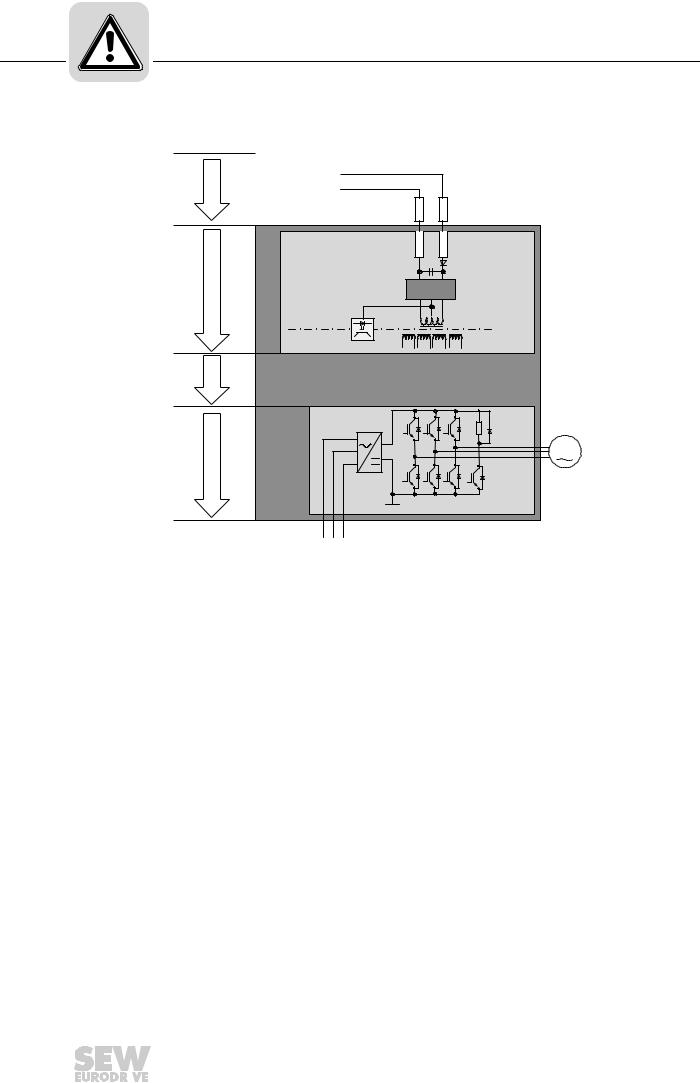
2.3Schematic representation – "safety concept for MOVITRAC® B"
[1] |
S24V |
|
|
S0V24 |
|
|
GND |
24V |
[2] |
S0V24 |
SVI24 |
|
|
|
|
SNT |
|
[3] |
|
|
[4] |
Uz+ |
|
|
|
|
|
|
M |
|
Uz- |
|
|
L1 L2 L3 |
|
1797262603
[1]Safety-related DC 24 V voltage supply
[2]Electrical isolation
[3]Voltage supply for control of power transistors
[4]Pulse width modulated signals for the output stage
Phone: 800.894.0412 - Fax: 888.723.4773 - Web: www.clrwtr.com - Email: info@clrwtr.com
8 |
|
|
Manual – Functional Safety MOVITRAC® MC07B |
|
|
|
|
|
|
|
|
|
|
|
|
Integrated Safety Technology |
2 |
|
Safety functions |
||
|
2.4Safety functions
The following drive-related safety functions can be used:
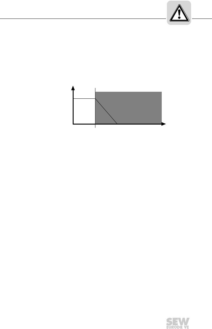
•STO (safe torque off according to EN 61800-5-2) by disconnecting the STO input.
If the STO function is activated, the frequency inverter no longer supplies power to the motor for generating torque. This safety function corresponds to a non-controlled stop according to EN 60204-1, stop category 0.
The STO input must be disabled by a suitable external safety controller/safety relay. The following figure shows the STO function:
v
|
t1 |
v |
Velocity |
t |
Time |
t1 |
Time at which STO is triggered |
|
Disconnection range |
t
2463228171
Phone: 800.894.0412 - Fax: 888.723.4773 - Web: www.clrwtr.com - Email: info@clrwtr.com
Manual – Functional Safety MOVITRAC® MC07B |
|
|
9 |
|
|
|
|
|
|
|
|
|
|
|
|
2 |
Integrated Safety Technology |
|
Safety functions |
||
|
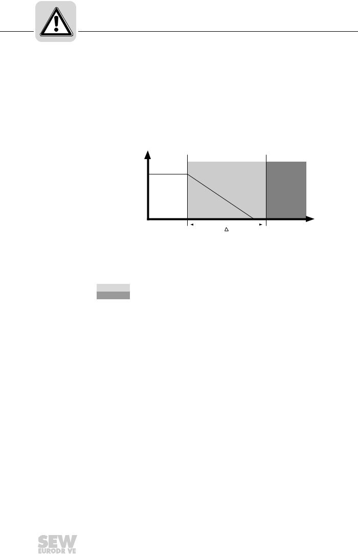
•SS1(c) (safe stop 1, function variant c according to EN 61800-5-2) by means of suitable external control (e.g. safety relay with delayed disconnection)
The following sequence is mandatory:
–Decelerate the drive using an appropriate brake ramp specified via setpoints.
–Disconnect the STO input (= triggering the STO function) after a specified safetyrelated time delay.
This safety function corresponds to a controlled stop according to EN 602041, stop category 1.
The following figure illustrates the SS1(c) function:
v
|
|
|
|
t |
|
t1 |
t |
||
|
t2 |
|||
|
|
|
|
2463226251 |
v |
Velocity |
|
|
|
t |
Time |
|
|
|
t1 |
Point of time when the brake ramp is initiated |
|
||
t2 |
Point of time when STO is triggered |
|
|
|
∆t |
Time between initiating the brake ramp and STO |
|
||
Safe time delay range
Disconnection range
Phone: 800.894.0412 - Fax: 888.723.4773 - Web: www.clrwtr.com - Email: info@clrwtr.com
10 |
|
|
Manual – Functional Safety MOVITRAC® MC07B |
|
|
|
|
|
|
|
|
|
|
|
|
 Loading...