


T
MOVITRAC® 31..
Frequency Inverters
INTERBUS Fieldbus Interface
(FFI31.. option and size 0/INTERBUS) Manual
Edition 1/99
0922 6915 / 199
08/198/96
CUL 
 UL
UL 


®®

Important Notes
Important Notes
•Read this user manual carefully before you start installation and commissioning work on MOVITRAC® frequency inverters with fieldbus options.
This user manual assumes that the user is familiar with and has at his disposal all relevant documentation on the MOVITRAC® system, particularly the installation and operating instructions.
•Safety notes:
Always follow the safety notes contained in this user manual. Safety notes are marked as follows:
Electrical hazard, e.g. during live working
Mechanical hazard, e.g. when working on hoists.
Important instructions for the safe and fault-free operation of the system, e.g. presetting before commissioning.Failure to follow these instructions may result in injury to people and damage to property.
•General safety notes for bus systems:
The fieldbus option gives you a communications system which allows you to match the MOVITRAC® 31.. drive system to the specifics of your application to a very high degree. As with all bus systems there is, however, the risk of parameters being changed, which will not show outside (i.e. the inverter) but affect the behaviour of the inverter. This may result in unexpected (not uncontrolled, though) system behaviour.
•In these instructions, cross-references are marked with an →, e.g.,
(→ MC_SHELL) means: Please refer to the MC_SHELL User Manual for detailed information
or information on how to carry out this instruction.
(→ section x.x) means: Further information can be found in section x.x of this user manual.
•Each unit is manufactured and tested to current SEW-EURODRIVE technical standards and specifications.
The manufacturer reserves the right to make changes to the technical data and designs as well as the user interface herein described, which are in the interest of technical progress. A requirement for fault-free operation and fulfilment of any rights to claim under guarantee is that these instructions and notes are followed.
These instructions contain important information for servicing, they should therefore be kept near the unit.
2 |
MOVITRAC® 31.. INTERBUS Fieldbus Interface |
|
Phone: 800.894.0412 - Fax: 888.723.4773 - Web: www.clrwtr.com - Email: info@clrwtr.com |

|
|
|
|
Contents |
|
|
|
|
|
|
|
|
|
|
|
|
|
Page |
|
|
1 |
Introduction .............................................................................................. |
4 |
|
|
||
2 Assembly / Installation Instructions ................................................................. |
6 |
|
|
|||
|
2.1 |
Fitting the FFI31.. interface............................................................................................... |
6 |
|
|
|
|
|
2.1.1 |
Scope of Delivery................................................................................................... |
6 |
|
|
|
|
2.1.2 |
Supported Inverter Types ...................................................................................... |
6 |
|
|
|
|
2.1.3 Fitting the Interface PCB ........................................................................................ |
6 |
|
|
|
|
2.2 |
Installing the MOVITRAC® 31.. size 0 with INTERBUS ...................................................... |
7 |
|
|
|
|
2.3 |
Pin Assignment................................................................................................................ |
8 |
|
|
|
|
2.4 |
Screening and Laying of the Bus Cables .......................................................................... |
9 |
|
|
|
|
2.5 |
Setting the Process Data Length...................................................................................... |
9 |
|
|
|
|
2.6 |
Display Elements ........................................................................................................... |
10 |
|
|
|
3 |
Configuring and Commissioning ................................................................... |
11 |
|
|
||
|
3.1 |
Inverter Control Mode ‘Fieldbus’.................................................................................... |
11 |
|
|
|
|
3.2 |
Parameter P801 “Save” ................................................................................................. |
12 |
|
|
|
|
3.3 |
Bus Topologies with MOVITRAC® 31.. .......................................................................... 13 |
|
|
||
|
|
3.3.1 Direct Connection to DCB Master Modules.......................................................... |
13 |
|
|
|
|
|
3.3.2 Direct Connection to DAB Master Modules.......................................................... |
14 |
|
|
|
|
|
3.3.3 Integration in 8-Wire Remote Bus Systems......................................................... |
14 |
|
|
|
|
3.4 |
Inverter Module Identity................................................................................................. |
15 |
|
|
|
|
3.5 |
Configuring the Master Module ..................................................................................... |
15 |
|
|
|
|
|
3.5.1 Configuring for 1 Process Data Word.................................................................. |
16 |
|
|
|
|
|
3.5.2 Configuring for 2 Process Data Words ................................................................ |
17 |
|
|
|
|
|
3.5.3 Configuring for 3 Process Data Words ................................................................ |
18 |
|
|
|
4 |
The PMS Interface .................................................................................... |
19 |
|
|
||
|
4.1 |
PMS Services ................................................................................................................ |
19 |
|
|
|
|
|
4.1.1 |
Initiate ................................................................................................................. |
19 |
|
|
|
|
4.1.2 |
Abort ................................................................................................................... |
20 |
|
|
|
|
4.1.3 |
Reject .................................................................................................................. |
20 |
|
|
|
|
4.1.4 |
Identify ................................................................................................................ |
20 |
|
|
|
|
4.1.5 |
Get-0V ................................................................................................................. |
20 |
|
|
|
|
4.1.6 |
Status .................................................................................................................. |
20 |
|
|
|
|
4.1.7 |
Read .................................................................................................................... |
20 |
|
|
|
|
4.1.8 |
Write.................................................................................................................... |
20 |
|
|
|
4.2 |
Object List...................................................................................................................... |
21 |
|
|
|
|
|
4.2.1 |
Object Description of the Drive Parameters........................................................ |
21 |
|
|
|
|
4.2.2 “Download Parameter Block” Object ................................................................... |
22 |
|
|
|
|
|
4.2.3 “Universal Write Parameter” Object..................................................................... |
23 |
|
|
|
|
|
4.2.4 “Universal Read” Functionality Objects................................................................ |
24 |
|
|
|
5 Parameter Adjustment Return Codes .............................................................. |
27 |
|
|
|||
|
5.1 |
Internal Communications Error...................................................................................... |
27 |
|
|
|
6 |
Technical Data ........................................................................................ |
28 |
|
|
||
|
6.1 |
FFI31.. Interface Technical Data ..................................................................................... |
28 |
|
|
|
|
6.2 |
Technical Data MOVITRAC® 31.. BG0/INTERBUS............................................................ |
29 |
|
|
|
|
Appendix A |
............................................................................................. |
30 |
|
|
|
|
Index .................................................................................................... |
|
31 |
|
|
|
MOVITRAC® 31.. INTERBUS Fieldbus Interface |
3 |
Phone: 800.894.0412 - Fax: 888.723.4773 - Web: www.clrwtr.com - Email: info@clrwtr.com

1 Introduction
1 Introduction
This FFI 31.. INTERBUS Interface Manual describes the procedure for installing the FFI 31C INTER- BUS Interface in the inverter and for commissioning the MOVITRAC® 31.. size 0 inverter with integrated INTERBUS interface when connected to an INTERBUS fieldbus system.
In addition to describing all the settings on the fieldbus interface, this manual further discusses the various options for connecting the inverter to INTERBUS in the form of brief commissioning examples.
In addition to this INTERBUS Interface Manual, you should order the following more detailed documentation on the INTERBUS fieldbus interface in order to connect the MOVITRAC® 31.. simply and efficiently to the INTERBUS fieldbus system
•MOVITRAC® 31.. Fieldbus Unit Profile Manual (Order no. 0922 7016)
•MOVITRAC® 31.. Communications Interfaces and Parameter List (Order no. 0923 0580)
The MOVITRAC® 31.. Fieldbus Unit Profile Manual gives a detailed description of the fieldbus parameters and their codings and discusses various control concepts and application options in the form of brief commissioning examples.
The MOVITRAC® 31.. Parameter List contains a list of all the inverter’s parameters that can be read or written via the various communication interfaces such as the RS-232, RS-483 and via the fieldbus interface.
The MC_Shell software makes it straight forward and easy to operate the inverter and set the parameters, including the parameters for the fieldbus. This software can be ordered from SEW under the number 0921 2949.
MOVITRAC® 31.. and INTERBUS
The inverter unit profile for INTERBUS mode, i.e. the way the inverter operates and responds when in INTERBUS mode, is independent of the type of fieldbus, and thus consistent for all fieldbus types. This allows the user to develop his drive applications independent of a particular fieldbus or change to another bus system, e.g. the open standardized PROFIBUS-DP/FMS (FFP 31C option) fieldbus system.
MOVITRAC® 31.. offers digital access to all drive parameters and functions via the INTERBUS Interface. The inverter is controlled by the high-speed cyclic process data. This process data channel provides the facility to specify setpoints such as setpoint speeds, ramp generator times for acceleration and deceleration etc., as well as various drive functions such as enable, controller inhibit, stop, rapid stop, etc. to be triggered. This channel can also be used to read back actual values from the inverter, such as actual speed, current, unit status, error number or reference messages.
Whereas process data are generally exchanged in cycles, the drive parameters can only be read and written acyclically via the READ and WRITE services. This exchange of parameter data enables applications where all major drive parameters are stored in the higher-level automation unit to be implemented, thus avoiding manual adjustment of parameters on the inverter itself, which can often be very time-consuming.
4 |
MOVITRAC® 31.. INTERBUS Fieldbus Interface |
|
Phone: 800.894.0412 - Fax: 888.723.4773 - Web: www.clrwtr.com - Email: info@clrwtr.com |
Introduction 1
Controller
INTERBUS Master
|
|
|
|
|
Frequency inverter |
|
|
|
|||
|
|
MOVITRAC |
|
|
MOVITRAC |
|
|
MOVITRAC |
|
INTERBUS-S |
|
|
|
|
|
|
|
|
Module Ident. |
||||
8 41 |
F E LD B U S |
8 4 1 |
F E L DB U S |
8 41 |
F E L D BU S |
|
227 |
||||
841 |
Fieldbus |
||||||||||
ST E U ER M O D E |
|
S T EU ER M OD E |
|
ST E U ER M O D E |
|||||||
SE W |
|
SE W |
SE W |
|
CONTROL MODE |
||||||
|
|
|
|
|
|
|
|
||||
E |
Q |
|
E |
Q |
|
E |
Q |
|
|
|
|
|
|
|
|
|
|
|
|
|
E |
Q |
|
|
SEW |
|
|
SEW |
|
|
SEW |
|
|
|
|
|
E U RO D R I VE |
|
|
E U R OD R IV E |
|
|
E U R OD R I VE |
|
|
|
|
P |
INTERBUS |
P |
P |
P |
Input/output modules
P |
INT ERBUS
00469AEN
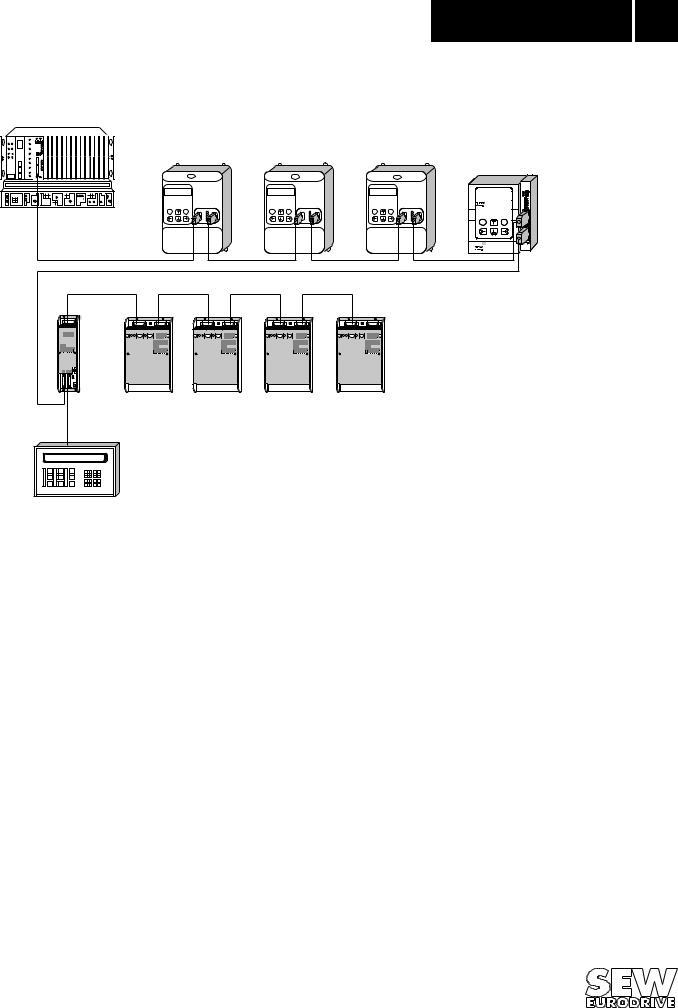
Fig. 1: INTERBUS with MOVITRAC® 31..
The INTERBUS Interface option pcb is designed so that all INTERBUS specific settings, such as the process data length, can be made on the interface by means of a hardware switch. These manual settings enable the inverter to be integrated into the INTERBUS system and switched on in a very short space of time. Parameters can be set fully automatically by the higher-level INTERBUS master (parameter download). This forward-looking version offers the benefits of a shorter commissioning period for the plant as well as simpler documentation of the application program, as all major drive parameter data can now be recorded directly in the control program.
The use of a fieldbus system in drive technology requires additional monitoring functions, such as fieldbus timeout or special emergency stop concepts. The monitoring functions of the MOVITRAC® 31.. can be matched to the specific application for which it is to be used. This feature enables you, for instance, to specify which error response the inverter should trigger if an error should occur in the bus. A rapid stop will be practical for many applications, but it is also possible to freeze the last setpoints, so that the drive can continue with the last valid setpoints (e.g. conveyor belt). As the functionality of the control terminals is also ensured when the inverter is operated in the fieldbus mode, fieldbus-independent emergency stop concepts can still be implemented via the inverter’s terminals.
The MOVITRAC® 31.. inverter offers numerous diagnostic facilities for commissioning and servicing. For instance, both the setpoints transmitted from the higher-level control unit as well as the actual values can be checked with the fieldbus monitor in the hand-held keypad. It also provides you with a lot of additional information on the status of the fieldbus option pcb. The PC software MC_SHELL offers even more convenient diagnostic facilities in that it provides a detailed display of the fieldbus and unit status information as well as the facility to set all the drive parameters (including the fieldbus parameters).
MOVITRAC® 31.. INTERBUS Fieldbus Interface |
5 |
Phone: 800.894.0412 - Fax: 888.723.4773 - Web: www.clrwtr.com - Email: info@clrwtr.com

2
6
Assembly / Installation
Instructions
2 Assembly / Installation Instructions
The following section describes assembly and installation of the MOVITRAC® 31.. inverter for integration in an Interbus system.
Sizes 1...4 of the MOVITRAC® 31.. inverter are connected to the INTERBUS via the FFI31 interface. The standard basic unit of the MOVITRAC® 31.. Size 0 contains an integrated Interbus interface.
To set the fieldbus parameters you will need the FBG31.. keypad for MOVITRAC® 31.. and/or the latest version of the MC_SHELL software.
2.1Fitting the FFI31.. interface
This option is either delivered separately, so that you will have to install it yourself, or you can order an inverter which comes complete with the FFI31 interface installed.
2.1.1 Scope of Delivery
The FFI31 interface comprises the following components:
–1 FFI31C (INTERBUS) interface pcb
–3 fastening screws
–1 housing cover
–earthing clamp for the outgoing remote bus Please check to see that delivery is complete.
2.1.2Supported Inverter Types
The FFI31.. interface for connection to an INTERBUS system can be operated with the MOVITRAC® 31 inverters sizes 1...4 as follows:
FFI31A interface: |
for MOVITRAC® 31B inverters when the service code of the size 4 group is |
|
greater than or equal to 14 (→ Assembly and Installation of MOVITRAC®31B, |
|
Sec. 4). |
FFI31C interface: |
for all MOVITRAC®31C inverters, sizes 1...4. |
2.1.3 Fitting the Interface PCB Before you begin:
•Before touching the pcb discharge yourself with the appropriate measures (earthing band, conductive shoes, etc.)
•Store the pcb in the original package and only unpack immediately before installation.
•Do not touch the pcb more often than necessary and hold only by the edges. Do not touch components.
Installation of the pcb:
•Disconnect inverter from the supply. Switch off mains supply and, if applicable, the 24 V supply.
•Take off the lower protective cover.
•Unscrew and remove the housing (screw located under the cover for the keypad).
•Unscrew the EPROM pcb and remove it from the X20 connector.
•Push the FFI31.. pcb into the X20 connector and fasten with the screws.
•Take the fitted cover out of the housing and replace it with the cover delivered with the option.
•Replace the housing and fasten with the screws.
•Replace the lower protective cover.
The FFI31.. is now completely fitted.
MOVITRAC® 31.. INTERBUS Fieldbus Interface
Phone: 800.894.0412 - Fax: 888.723.4773 - Web: www.clrwtr.com - Email: info@clrwtr.com
Assembly / Installation |
|
2 |
Instructions |
|
|
|
|
|
|
|
|
MOVITRAC® processor pcb |
EPROM |
|
|
|
|
|
|
|
Process data length |
||
|
|
|
|
||
|
|
DPRAM |
|
|
|
|
|
|
Processor |
|
|
|
|
EPROM |
Supi |
LED green: UL |
|
|
|
|
|||
|
X20: |
|
LED green: RC |
||
|
Flash |
|
LED green: BA |
||
|
|
|
LED green: TR |
||
|
|
|
|
LED red: |
RD |
|
|
X9: |
X10: |
|
|
S1 |
|
|
|
|
|
X2: |
X3: |
Two-wire |
Two-wire |
|
|
|
|
|
|||
|
|
remote bus input |
remote bus output |
|
|
00305AEN
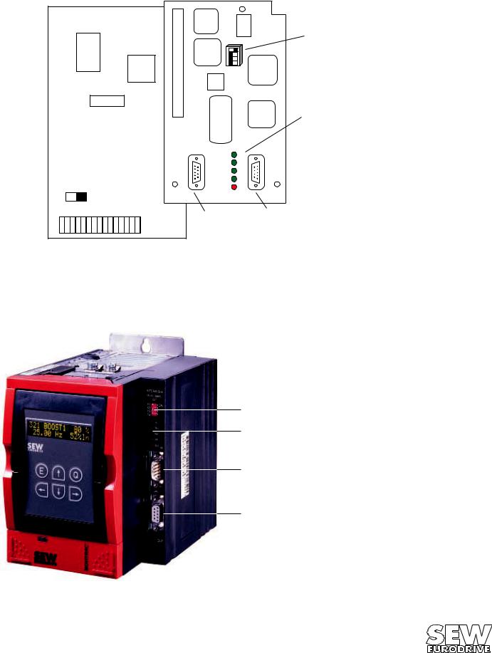
Fig. 2: FFI31.. option
2.2Installing the MOVITRAC® 31.. size 0 with INTERBUS
Size 0 inverters (MOVITRAC® 31.. Size 0 with INTERBUS) have the INTERBUS interface already installed as a standard in the basic unit (→ Fig. 3).
1 DIP switch for setting the process data length.
2 Five LEDs for diagnosis of the INTERBUS system.
3 9-pin sub-D connector, male
1(input for remote bus).
24 9-pin sub-D connector, female, (output for remote bus).
3
4
02125AXX
Fig. 3: MOVITRAC ® Inverter with INTERBUS interface and the FBG31 keypad.
MOVITRAC® 31.. INTERBUS Fieldbus Interface |
7 |
Phone: 800.894.0412 - Fax: 888.723.4773 - Web: www.clrwtr.com - Email: info@clrwtr.com
2 |
|
Assembly / Installation |
|
Instructions |
|
|
|
|
|
|
|
2.3Pin Assignment
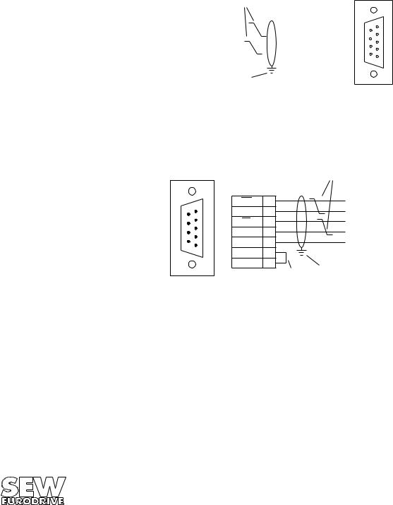
The MOVITRAC® 31.. inverter is connected to the INTERBUS system via the 2-wire remote bus by a 6-core screened cable with twisted-pair signal leads. The 2-wire remote bus basically consists of an RS-485 Data Out channel (signal lines DO and DO) as well as of the RS-485 Data In channel (signal lines DI and DI).
There is a 9-pin sub-D connector (male) for the remote bus output and a 9-pin sub-D connector (female) for the remote bus input on the inverter itself. The incoming remote bus cable must have a female 9-pin sub-D connector and the outgoing remote bus cable must have a male 9-pin sub-D connector.
Incoming remote bus on the remote bus input.
Twisted-pair signal |
9-pin sub-D |
cables |
connector (female) |
|
Green |
|
6 |
|
DO |
|
|
|
|
|||
Yellow |
|
1 |
|
DO |
|
|
|
||||
Pink |
|
7 |
|
DI |
|
|
|
||||
Grey |
|
2 |
|
DI |
|
|
|
||||
Brown |
|
3 |
COM |
||
|
|||||
Conductive connection between connector housing and screen.
6 |
1 |
7 |
2 |
8 |
3 |
94
5
02092AEN
Fig. 4: Assignment of the 9-pin sub-D connector of the incoming remote bus cable
Outgoing remote bus on the remote bus output.
9-pin sub-D
connector (male) |
|
|
||
|
1 |
DO |
6 |
|
6 |
DO |
1 |
||
23 |
||||
7 |
DI |
7 |
||
8 |
4 |
DI |
2 |
|
9 |
5 |
COM |
3 |
|
|
||||
|
|
|
||
|
|
|
5 |
|
|
|
|
9 |
|
Bridged
Twistet -pair signal cables
Green
Yellow
Pink
Grey
Brown
Conductive connection between connector housing, cable shield.
02093AEN
Fig. 5: Assignment of the 9-pin sub-D connector of the outgoing remote bus cable
8 |
MOVITRAC® 31.. INTERBUS Fieldbus Interface |
|
Phone: 800.894.0412 - Fax: 888.723.4773 - Web: www.clrwtr.com - Email: info@clrwtr.com |

Assembly / Installation |
|
2 |
Instructions |
|
|
|
|
|
|
|
|
2.4Screening and Laying of the Bus Cables
The INTERBUS Interface supports RS-485 transmission technology and requires as a physical medium the 6-core, screened, two-wire twisted-pair cable specified for INTERBUS.
Technically correct screening of the bus cable absorbs the electrical interference that can occur in an industrial environment. You will achieve the best screening results if you adopt the following measures:
•Hand-tighten the fixing screws of plugs, modules and equipotential bonding conductors
•Only use plugs with metal or metal-plated housings
•Connect the screening in the plug over as large an area as possible
•Connect the screening at both ends of the bus cable
•Do not lay signal and bus cables parallel to power cables (motor leads), but wherever possible in separate cable conduits
•In an industrial environment use metallic, earthed cable trays
•Run signal cables and the associated equipotential bonding conductor as close as possible to each other, using the shortest route
•Avoid extending bus cables through the use of connectors
•Run the bus cables close to existing earthed surfaces
IMPORTANT!
In the event of fluctuations in the earth potential, a circulating current may flow through any screening which may be connected at both ends and connected to the earth potential (PE). In this case, ensure there is adequate equipotential bonding in accordance with the relevant safety provisions.
In the event of further questions regarding the installation of the bus system, refer to the INTERBUS installation manual IBS SYS INST UM (Order No. 2754286, PHOENIX CONTACT), from which the points mentioned above were also taken.
2.5Setting the Process Data Length
The MOVITRAC®31.. inverter communicates via INTERBUS with the higher-level control both via the rapid cyclical process data channel and via the acyclical parameter channel (PCP, Peripherals Communication Protocol). The number of process data words to be transmitted in the process data channel is variable and can be adjusted using the DIP switches on the INTERBUS Interface. In general you have a choice between one, two and three process data words. In all three cases, the inverter can be parameterized at any time via the PCP channel.
ON
S1
S2
S3
S4
1 |
|
|
|
|
|
|
|
|
|
3 2 |
|
|
|
OPEN |
|
|
|
||
|
|
|
||
|
|
|
||
|
|
|
||
4 |
|
|
|
|
|
|
|
|
|
|
|
|
|
|
|
|
|
|
|
S1 S2 |
|
OFF OFF -- |
|
OFF ON 1PD |
|
ON |
OFF 2PD Setting as supplied: 2PD |
ON |
ON 3PD |
00308AEN
Fig. 6: Setting the process data length in process data words
MOVITRAC® 31.. INTERBUS Fieldbus Interface |
9 |
Phone: 800.894.0412 - Fax: 888.723.4773 - Web: www.clrwtr.com - Email: info@clrwtr.com
2 |
|
Assembly / Installation |
|
Instructions |
|
|
|
|
|
|
|
An example of the DIP switch settings for all three data process lengths is shown in Fig. 7 below. Switches S3 and S4 are not allocated. These DIP switches are only evaluated when the inverter is started up, i.e. when power is connected (mains and external 24 V supply). This means that the inverter has to be switched on again when the process data length is changed (mains and 24 V).
ON |
ON |
ON |
S1 |
1 |
|
|
|
|
|
S1 |
1 |
|
|
|
|
|
|
|
|
|
|
|
|
|
|
|
||||
S3 |
32 |
|
|
|
OPEN |
|
S3 |
32 |
|
|
|
OPEN |
|
|
|
|
|
|
|
|
|
||||||
S2 |
|
|
|
|
|
|
S2 |
|
|
|
|
|
|
S4 |
4 |
|
|
|
|
|
S4 |
4 |
|
|
|
|
|
|
|
|
|
|
|
|
|
|
|
||||
|
|
|
|
|
|
|
|
|
|
||||
|
|
|
|
|
|
|
|
|
|
|
|
|
|
|
|
|
|
|
|
|
|
|
|
|
|
|
|
Setting: |
|
|
Setting: |
|
|
||||||||
1 process data word |
2 process data words |
||||||||||||
Fig. 7: Example for setting the process data length
S1 |
1 |
|
|
|
|
|
|
|
|
||
S3 |
32 |
|
|
|
OPEN |
|
|
|
|||
S2 |
|
|
|
|
|
S4 |
4 |
|
|
|
|
|
|
|
|
||
|
|
|
|
||
|
|
|
|
||
|
|
|
|
|
|
|
|
|
|
|
|
Setting:
3 process data words
00309AEN
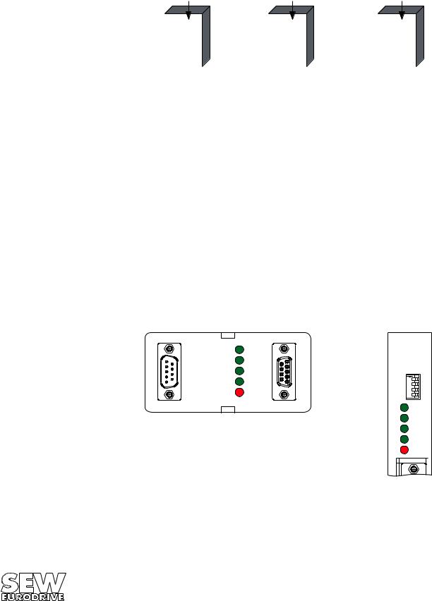
2.6Display Elements
The FFI 31C.. interface has five LEDs for diagnosing the INTERBUS system. These LEDs provide information about the status of the INTERBUS system. The meaning of each LED is shown in Table 1.
LED Name |
Colour |
Status |
Meaning |
|
|
|
|
UL (green) |
green |
on |
Logic voltage FFI 31 C interface |
|
|
|
|
RC (green) |
green |
on |
Incoming remote bus ready for operation (remote bus link o.k.) |
BA |
green |
on |
Bus in operation |
TR |
green |
on / flickering |
Parameter data exchange via PCP channel |
|
|
|
|
RD |
red |
on |
Onward remote bus off |
Table 1: Meaning of the diagnostic LEDs for INTERBUS
Order of LEDs in |
|
|
the MOVITRAC® 31.. sizes 1...4 |
the MOVITRAC® 31.. size 0 |
|
UL |
INTERBUS-S |
|
Module Ident. |
||
RC |
||
227 |
||
BA |
||
|
||
TR |
|
|
RD |
|
|
|
UL |
|
|
RC |
|
|
BA |
|
|
TR |
|
|
RD |
|
Fig. 8: Display elements |
00310BXX |
|
|
10 |
MOVITRAC® 31.. INTERBUS Fieldbus Interface |
|
Phone: 800.894.0412 - Fax: 888.723.4773 - Web: www.clrwtr.com - Email: info@clrwtr.com |
 Loading...